
Abstract
This paper propose a novel Port Controlled Hamiltonian_Backstepping (PCH_BS) control structure with online tuned parameters, in combination with the modified Stator Current Model Reference Adaptive Syatem (SC_MRAS) based on speed and flux estimator using Neural Networks(NN) and sliding mode (SM) for sensorless vector control of the six phase induction motor (SPIM). The control design is based on combination PCH and BS techniques to improve its performance and robustness. The combination of BS_PCH controller with speed estimator can compensate for the uncertainties caused by the machine parameter variations, measurement errors, and external load disturbances, enables very good static and dynamic performance of the sensorless drive system (perfect tuning of the speed reference values, fast response of the motor current and torque, high accuracy of speed regulation) in a wide speed range, and robust for the disturbances of the load, the speed variation and low speed. The proposed sensorless speed control scheme is validated through Matlab-Simulink. The simulation results verify the effectiveness of the proposed control and observer.
Keywords
Introduction
In recent decades, the multiphase motor drives are widely used in much applications due to their inherent features such as higher torque density, greater efficiency, reduced torque pulsations, fault tolerance, and reduction in the required rating per inverter leg [1]. Especially, These drives are often considered in some applications such as locomotive traction, electrical ship propulsion, in high power applications such as automotive, aerospace, military and nuclear [2]. With its reliable working characteristics and high failure tolerance nowadays, this motors are even considered in the small power applications requiring high reliability and fault tolerance, where are expected that the loss of one or more phases the machine still can provide a significant electromagnetic torque to continue operating the system. Among the many types of multiphase motors, SPIM is one of the most widely used multiphase motors.
As the three phase induction motor, when uncertainties and disturbances are appreciable, traditional control techniques using PID control for SPIM drives are not able to guarantee optimal performance or can require a considerably time consuming and plant dependent design stage. Therefore, to overcome these drawbacks the nonlinear control techniques have been followed, such as, for instance, linear output feedback control [3, 4], Sliding mode (SM) [5, 6], Backstepping control (BS) [8–12], Fuzzy Logic (FL) control [13, 14] neural networks (NN) control [15–17], predictive control, [18], Hamiltonian control [19–24].
Among these techniques, the BS design techniques have received great attention due to its systematic and recursive design methodology for nonlinear feedback control [29]. The BS design can be used to force a nonlinear system to behave like a linear system in a new set of coordinates. The major advantages are that it has the flexibility to avoid cancelations of useful nonlinearities and pursues the objectives of stabilization and tracking. The disadvantages of this technique are the detailed and accurate informations about dynamical system be required when designing traditional BS. Many strategies have been proposed to overcome these drawback. In [25] the authors proposed a new BS control scheme using a dynamical induction motor model based on the tranditional BS control with the unknown of the damping coefficient, the motor inertia, the load torque and the uncertainty of the machine parameters. The tests carried out without applying a load torque. However, the speed ripple and the performance of the tracking the reference speed was not good, and it also did not guarantee a total rejection of the load torque disturbance. In [26, 27], an integral version of the control and an adaptive observer using the backstepping technique was proposed. The results showed the good performance of the control law and the observer, but it may be noted that the problem with this method was the complexity of solving differential equations, which required more computing time for processor, since the model was increased by two states. An other scheme was proposed in [10]. The BS design method for both the control and observer, by adding the integral error tracking component to increase the stability of the transmission system, this method for good dynamic response, precise controls. However, the torque ripple was recorded as quite large, the performance at low speed range and regenerating modes not reported in [10].
From the above analysis it is easy to see that the BS control, which represents a precise model based control method, was difficult to obtain satisfactory control performance when using independently, especially in the cases applyed to control the nonlinear systems. Therefore, to solve this problem, beside continue to improve BS strategy, another appoach have paid more and more attention to the composite control strategy which combines BS method with other control methods, such as sliding mode control [28–30], neuron network [31–35], fuzzy logic system (FLS) [36, 37].
The other side, as we known that these control techniques can not guarantee good performances without the use of suitable state observer. Further, the use of the sensors in the SPIM drive systems make increase the cost and reduce the reliability of the control systems. Therefore, there has been a lot of attention from researchers to reduce the number of sensors and improve the performance of the observers. The various strategies based on the machine fundamental excitation model have been proposed for machine parameter and speed estimation in sensorless SPIM drives. Among these techniques MRAS are the most common strategy implemented due to their low computational effort and simplicity [40]. Beside, NN techniques have attracted much attention in the recent times as powerful tools to solve many estimation and control problems. Various NN based techniques have been successfully applied to electric drives. In general increased robustness against parameter variations and improved performance are expected when these methods are employed, which encourages the application of these techniques to improve sensorless control. Compared to tranditional control strategies, NN techniques eliminate the need for mathematical models which are often complicated and rely on several assumptions with some parameters that may be difficult to measure. Therefore, more robustness with respect to parameter variation is expected when using such schemes. Moreover, due to their adaptive capabilities these techniques may lead to improved performance when combined with methods.
In this paper, to improve and enhance the performance of the sensorless vector control for SPIM, the author proposes:
–A new combined control structure: The BS controller is applied in outter speed closed loop control, the model parameters of SPIM (Rr, rotor flux) are updated the controller to minimize the effect of parameter changes on the controller’s performance. BS based controller design, the integral error tracking component added to improve its sustainability. In addition, to further enhance the performance of the SPIM drive system, the authors proposed a new structure combining BS and PCH, a proposed PCH for inner current control loop to improve performance and ensure the stability, accuracy speed response for the drive system, enhance the robustness for the sensitivity of changes in machine parameters, load disturbance.
–The accurate estimation of the rotor flux, resistance values of Rs and Rr and speed by the improved stator current based on reference model adaptive system using neuron network and sliding mode (NNSM_SC_MRAS) to enhance the performance of observer and controller for the high performance SPIM drives. In this SC_MRAS scheme are, first: Adaptive Model uses a two layer linear neural network, which is trained online by a linear LS algorithm, this algorithm requires the less computation effort and overcome some drawbacks, which cause by its inherent nonlinearity as in literature published before [41]. This significantly improves the performance of the proposed observer. Second: The adaptive model based on NN is implemented in the prediction mode. This improvement ensures the proposed observer operate better accuracy and stability. Third: An rotor flux identifier, which is needed for the stator current estimation of the adaptive model and controller, is proposed based on SM. The gains are designed based on stability conditions of Lyapunov theory. This solution improves the rotor flux estimation accuracy, and consequently, the speed estimation accuracy at very low stator frequency operation. Finally, the modified Euler integration has been used in the adaptive model to solve the instability problems due to the discretization of the rotor equations of the machine enhance the performance of observer.
–The combination of the BS_PCH controller with the proposed NNSM_SC_MRAS speed estimator increases stability, compensates for the uncertainty caused by SPIM parameter variations, measurement errors and external load disturbances.
The effectiveness of this proposed control and observer structure is verified by simulation using MATLAB/ Simulink. The paper is organized into five sections, in section 2, the basic theory of the model of the SPIM and the SPIM drive are presented. Section 3 introduces the proposed BS_PCH cotroller and NNSM_ SC MRAS observer. Simulation and discuss are presented in Section 4. Finally, the concluding is provided in Section 5.
Model of SPIM
The system under study consists of an SPIM fed by a six-phase Voltage Source Inverter (VSI) and a DC link. A detailed scheme of the drive is provided in Fig. 1. By applying the Vector Space Decomposition (VSD) technique introduced in [18], the original six-dimensional space of the machine is transformed into three two-dimensional orthogonal subspaces in the stationary reference frame (D-Q), (x - y) and (zl -z2). This transformation is obtained by means of 6×6 transformation matrix (Equation 1):
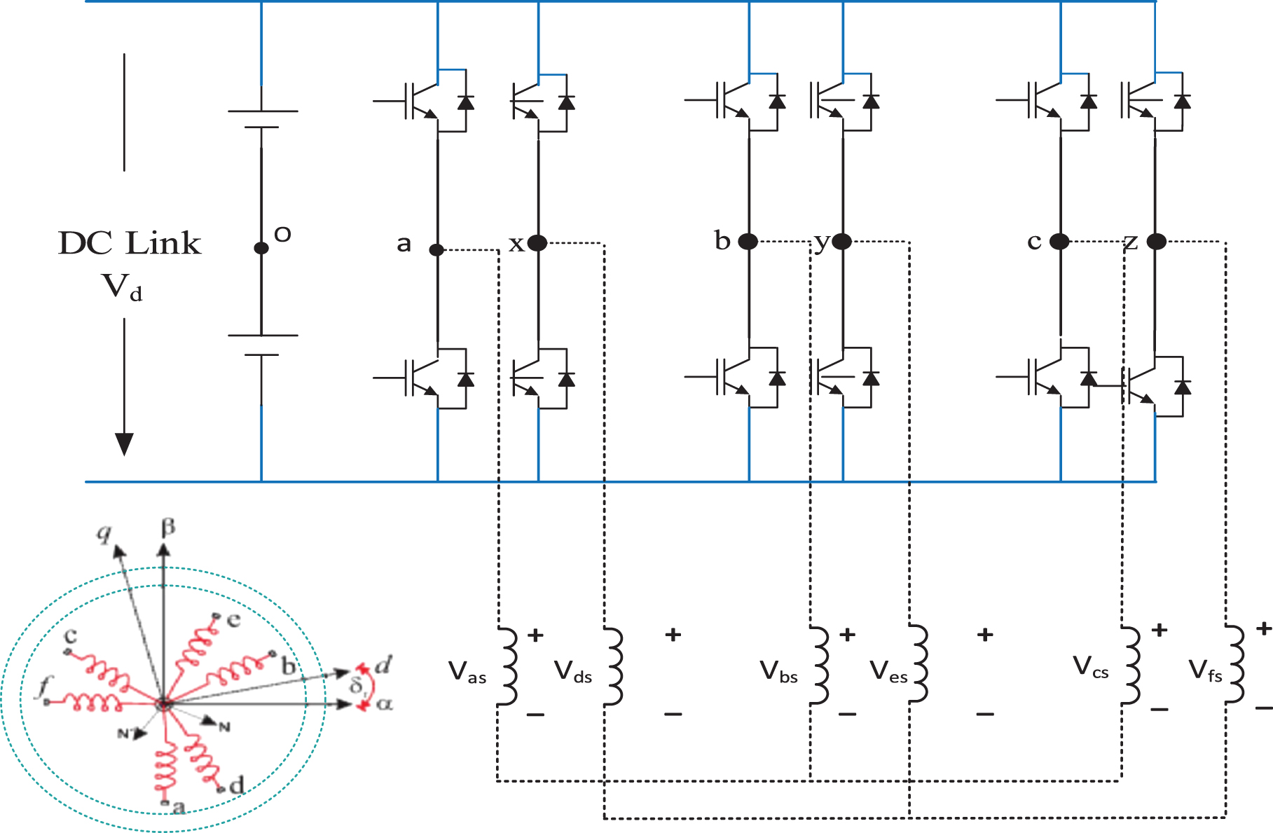
A general scheme of an SPIM drive.
In order to develop SPIM model for control purposes, some basic assumptions should be made. Hence, the windings are assumed to be sinusoidally distributed, the magnetic saturation, the mutual leakage inductances, and the core losses are neglected.
The electrical matrix equations in the stationary reference frame for the stator and the rotor may be written as
As these equations implies, the electromechanical conversion, only takes place in the D-Q subspace and the other subspaces just produce losses. Therefore, the control is based on determining the applied voltage in the αβ reference frame. With this transformation, the 6PIM control technique is similar to the classical three phase IM FOC. The control for the motor in the stationary reference frame is difficult, even for a three phase IM, so the transformation of SPIM model in a dq rotating reference frame to obtain currents with dc components [1] is necessary, a transformation matrix must be used to represent the stationary reference fame (α-β) in the dynamic reference (d - q). This matrix is given:
The field oriented control (FOC) is the most used strategy in the industrial field. Its objective is to improve the static and dynamic behavior of asynchronous machine unlike the scalar control. It allows decoupling the electromagnetic quantities in order to make the control similar to DC machine. The principle of the FOC is to align the d axis of the rotating frame (Dq(d-q)) with the desired flux as shown in Fig. 1. Therefore, the flux will be controlled by the direct component of the stator current (isd) and the torque by the quadratic component (isq). In this case we obtain: ψ
rq
= 0 ; ψ
rd
= ψ
rd
. Using Equations (1) and (4), the new model motor dynamics is described by the following space vector differential equations:
The new expression of the electromagnetic torque and the slip frequency are given by:
The proposed BS controller for outer speed control and rotor flux loops
The purpose of this study is to design a simple control law but for high dynamic and establishing performance, eliminating load disturbance and effect of motor parameter variations. The influence from the change of parameters and the load disturbance can be significantly reduced by adding a tracking error integration when designing the BS speed controller and updating the rotor resistance for BS control. BS techniques are a systematic and recursive method for synthesizing nonlinear control rules. The stability and performance of the subsystems is studied by Lyapunov theory [2]. Therefore, at each step of the design, a virtual command is created to ensure the convergence of subsystems.
As the rotor speed and flux are the tracking objectives, the tracking errors is defined as
The error dynamical equations are
To obtain the virtual controller of speed and rotor flux loop, the following Lyapunov function candidate is considered:
Differentiating V:
where:
We obtain:
The virtual controls in (12) are chosen to satisfy the control objectives and also provide references for the next step of the PCH design. Equation (12) can be expressed as Fig. 2.

The virtual inputs i sd and i sq .
A PCH system with dissipation is a representation of the form:
The Hamiltonian function of the system is given by
where:
Equation of the SPIM be described in a synchronously dq rotating reference frame (5) can then be rewritten in the PCH form (14) with:
Suppose we wish to asymptotically stabilize the system (14) around a desired equilibrium xo, a closed-loop energy function Hd (x) is assigned to the system which has a strict minimum at x0 (that is, Hd (x) > Hd (x0) for all x ≠ x0 in a neighborhood of x0). The feedback stabilization theory of PCH system is given as follows [6]. Given J(x), R(x), H(x), g(x) and the desired equilibrium xo. Assume we can find a feedback control u =α(x), Ra(x),Ja(x) and a vector function K(x) satisfying:
The closed-loop system:
The rotor flux ψ rd used in the Equation (12), (24) cannot be measured. This component is identified by CM and is presented in Section 3.3.3.1.
Structure of the NN_SC_ MRAS Speed Observer
In this scheme, the measured stator current components are also used as the reference model of the MRAS observer to avoid the use of a pure integrator and reduce influence of motor parameter variation as in [41, 42]. The adaptive model is a two-layer linear NN to estimate the stator current has been trained online by means of a least-squares algorithm. This adaptive model is described by the combined voltage- and current models in the stator reference frame, Then they been divided by Tn, be re written in the following as:
Its corresponding discrete model is, therefore, given by:
e
A
x
T
s
: is generally computed by truncating its power series ex pansion, i.e.,
If n = 1, the simple forward Euler method is obtained, which gives the following finite difference Equation [43]
where:
The integration method is more efficient than that used in (28) is the so called modified Euler integration [44]. In this case, a neural network can reproduce these equations, where and are the weights of the neural networks defined as (31).
Rearranging (30), the matrix equation is obtained in prediction mode; see (32). This matrix equation can be solved by any least square technique.(Equation 32)
Matrix Equation (32) can be written: Ax ≈ b, This is a classical matrix equation of the type, where A is called a “data matrix”, b is called an “observation vector,” and ωr is the scalar unknown. In this application a classical LS algorithm in a recursive form has been employed. This algorithm is described in detail in [45]. Figure 5 shows the block diagram of the NNSM_SC_ MRAS speed observer. In literature there exist three Least-Squares techniques, i.e. the Ordinary Least-Squares (OLS), the Total Least-Squares (TLS) and the Data Least-Squares(DLS) which arise when errors are respectively present only in b or both in A and in b or only in A. The LS technique solves for this problem by calculating the value of ωr which minimises the sum of squares of the distances among the elements (ai, bi), with i = 1,...m, and the line itself. OLS minimises the sum of squares of the distances in the b direction (error only in the observation vector). TLS minimises the sum of squares in the direction orthogonal to the line (for this reason TLS is also called orthogonal regression) while DLS minimises the sum of squares in the A direction (errors only in the data matrix). In this paper, authors focus on analysing OLS algorithm.
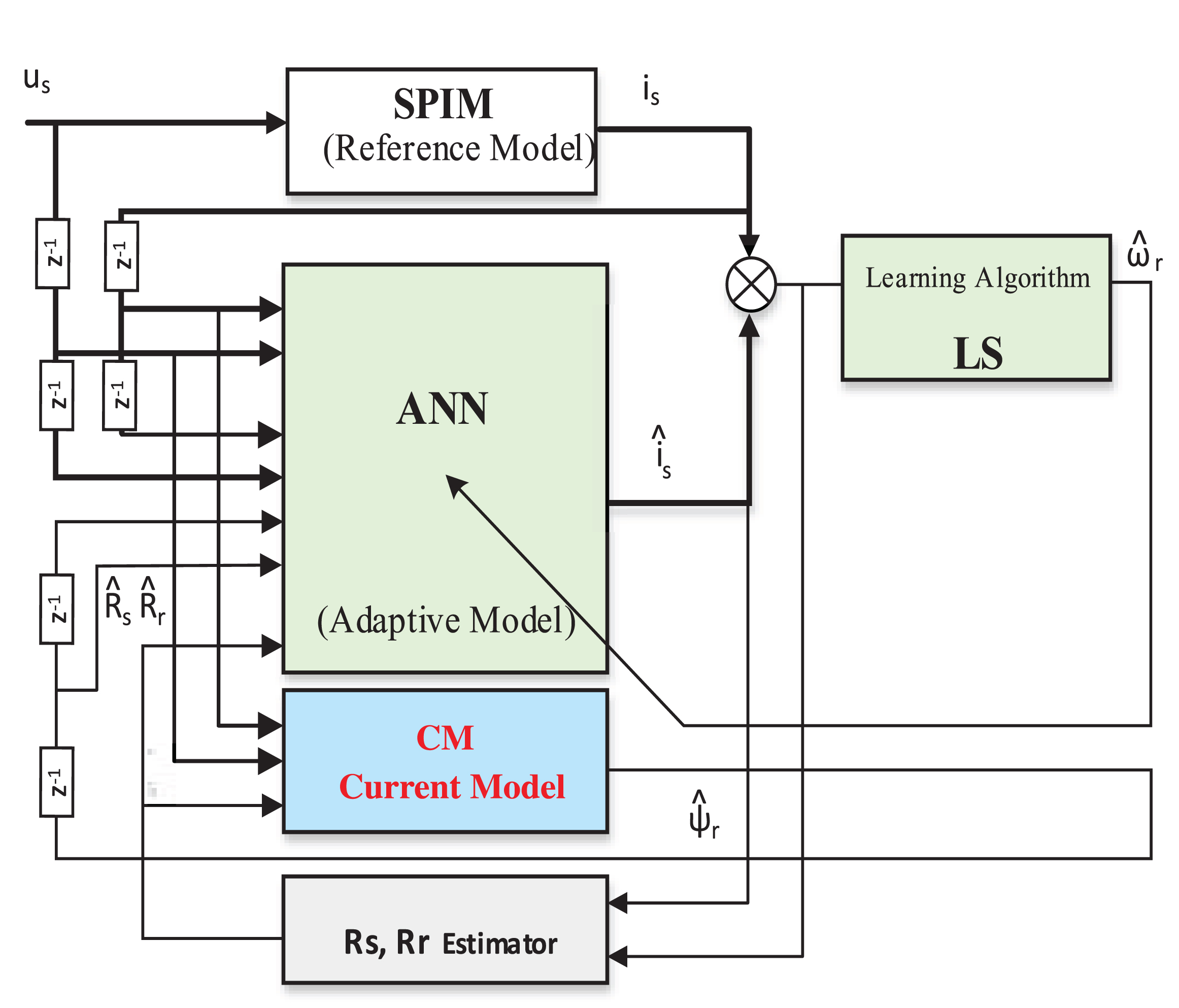
LS_ SC_ MRAS speed observer.
Ax ∼ b is the linear regression problem under hand. All LS problems have been generalized by using a parameterized formulation (generalized LS) of an error function whose minimization yields the corresponding solution. This error is given by:
Using OLS algorithm, this error is given by:
This error can be minimized with a gradient descent method:
3.3.3.1. Rotor Flux identifier and stability analysis: Consider a non-linear system described by:
where:
If the system is observable, the objective of the observer is to give the best state variables. From the measurement of output y and input u, the observer is defined by the follow structure:
With S is the slide surface of the observer is defined as following:
Subtracting (39) and (41) gives:
ɛ is the error vector defined by:
The aim of this section is to estimate the rotor flux components based on the stator currents and voltages that are easily measurable. From current model (CM), the flux estimation algorithm based on sliding-mode theory is defined:
From (20), the dynamic of the estimation error is given by:
By defining Lyapunov function as:
Whose time derivative is,
when the currents trajectory reaches the sliding surface ɛ1 =ɛ2 = 0, the observer error dynamics given by (25) behaves, in the sliding-mode as a reduced order system governed only by the roto flux error, because
The time derivative of the Lyapunov function candidate is:
When sliding takes place:
Choose Λ = ΔΓ-1 where
Note that det(Γ (ω r )) ≠ 0 for all ω r and so the inverse always exist. From (23), when sliding takes place, substituting from (28) yields:
This is, the flux observer error converges to zero with exponential rate of convergence.
3.3.3.2. Stator resistance online estimation: From (30–32) is easy see that, the resistance parameters necessary for estimating the speed. However, during motor operation, these parameters will change with the increase of temperature, especially, at low speed. Therefore to the performance improvement of the observer, especially at low speed, the resistances online identification is necessary.
In the proposed LS based adaptive speed observer the online Rs estimation methodologies proposed in [46] have been used, summarized in the following. In particular Rs is estimated on the basis of the isD, isD measured and
The estimated resistance values were update for the current observer to estimate the current exactly more.
The electric machine equation of SPIM can be written as:
where:
The overall equation is written of the speed observer can be written as:
The Equation (41) minus Equation (42) yields:
-
From Equation (43), it is eassy to see that:
defining the Lyapunov function candidate:
The time derivative of Lyapunov function in (45) can be calculated as:
The time derivative of
From (60) if t→ ∞,
a error function is used which is null if
Tù (49) và (50) yields:
In order to verify and evaluate the performance of the BS_PCH controller and NNSM_SC_MRAS speed observer for the sensorless vector control of SPIM drive system as shown in Fig. 8, the tests are devides tow part: Part 1 verify and evaluate the performance of the BS_PCH controller based on recommended benchmark tests [15, 17], part 2 verify and evaluate the performance of the BS_PCH controller combinate with NNSM_SC_MRAS speed observer based on recommended benchmark tests [10, 38].
SPIM parameters: 1HP, 220 V, 50 Hz, 4 pole, 1450 rpm. Rs = 10.1Ω, Rr = 9.8546Ω, Ls = 0.833457 H, Lr = 0.830811 H, m = 0.783106 H, Ji = 0.0088 kg.m2. Rs is nominal value of stator resistance.

Diagram of BS_PCH vector control for SPIM drives (IFOC).
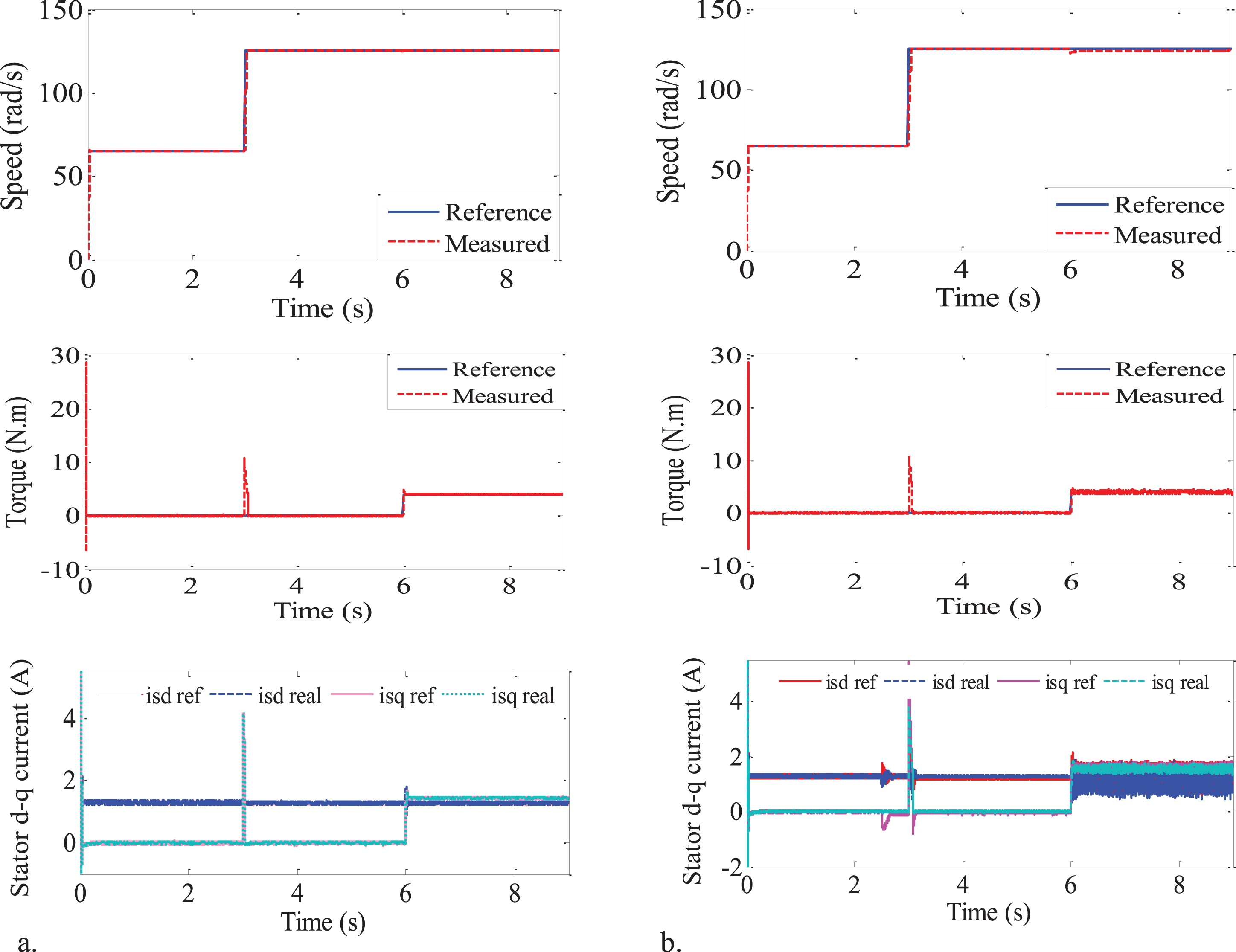
BS_PCH vector control with setting: a. Nominal rotor resistance; b. Rr* = 3Rr.
Tests in this section are conducted based on recommended benchmark tests [15, 17]. The vector control of SPIM drive system as shown in Fig. 4.
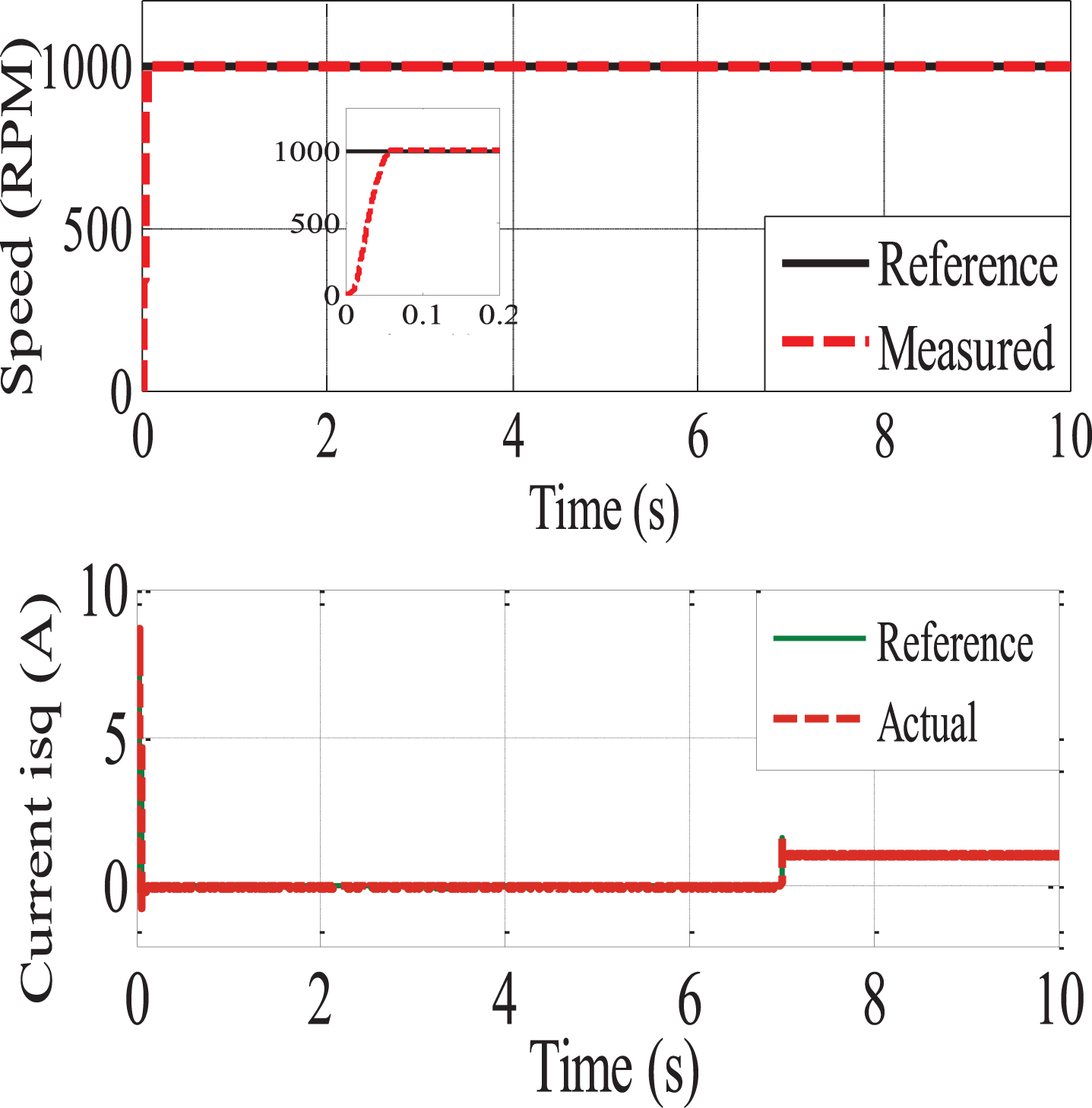
Test 1 is conducted based on recommended Benchmark tests in [15]. In this test, the reference speed are imposed from 650 rad/s increased to 125 rad/s at 3 s, 50% rated load applied at 6 s. The results in Fig. 4a show that the tracking reference performance of the BS_PCH scheme based on vector control is very well. Comparing with [15, Fig. 8a], it is easy to see that the BS_PCH controller give responses faster, more accurate and better the tracking reference performance than PI controller and NN controller in [15, Fig. 7a, Fig. 8a]. The dq stator current and torque responses (Figs. 5a) show that the BS_PCH vector control provides less current and torque oscillations than both the conventional and NN vector control in [15, Fig. 7c,d; Fig. 8c,d]. In order to assess the robustness of the proposed scheme for load disturbance at 6 s, observing the speed response in Fig. 5 a we see that error in tracking the speed increase not significantly at 6 s, the real speed instantly converges to the reference speed. For test in [15], there was an error in tracking the speed reference for both conventional vector control and NN vector control [15, Fig. 7a, Fig. 8a], these errors in tracking the speed reference are higher than that appeared in BS_PCH vector control scheme.
This test is implemented to evaluate the performance of the proposed BS_PCH vector control under motor parameter variation condition and load disturbance. The extreme conditions are surveyed with the rotor resistance value was setup increased Rr’ = 3Rr at 2.5 s, the reference speed are imposed from 650 rad/s increased to 125 rad/s at 3 s, 50% rated load applied at 6 s. Figures 5b show the speed, torque and current responses of the proposed BS_PCH vector control scheme, respectively [15].
These simulation results show that the proposed control scheme can provide the performance well when facing the parameter uncertainty and load disturbance. The speed and current responses are almost unaffected until 50% rated load has been applied to motor. When applying load, error speed tracking and ripple current and torque increased slightly. However, comparing to NN control [15, Fig. 10a] and conventional PI control in [15, Fig. 9a], it is easy to see that the proposed scheme in this paper give better performance, more robustness for the uncertain motor parameter of and load disturbance. The results in Fig. 5b show that the torque and current oscillations of the proposed in this paper less than the conventional PI vector control [15, Fig. 9(b,c)] and NN control [15, Fig. 10 (b,c)]. The PCH scheme handle current loops quite efficiently, the compensation function Ha added to keep system always work stably at reference values. The dq stator current responses in extreme condition Rr increased 300%, 50% rated load are better than NN control
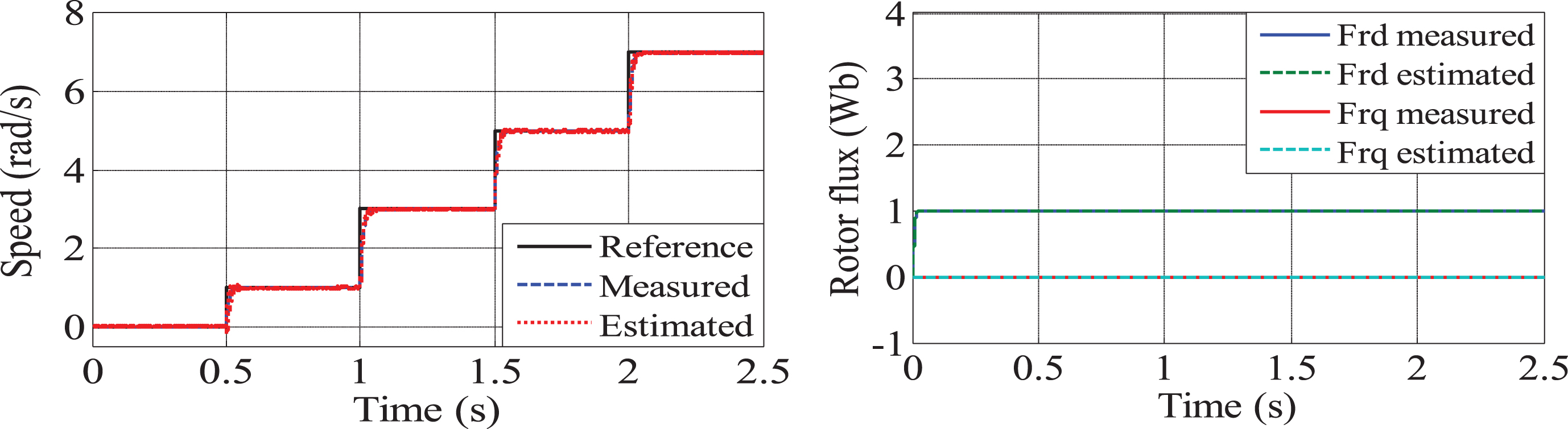
The speed and torque responses in case of speed variations without load.
The speed and torque responses in case of constant speed.

Sensorless vector control of SPIM drive using BS_PCH control and NNSM_SC_MRAS observer.
a. The performance of SPIM drive at low speed: Step Response.
b. The performance of SPIM drive at low speed: Ramp Responses.
In order to verify and evaluate the performance of the proposed BS_PCH vector cotrol and NNSM_SC_MRAS speed observer for sensorless vector control of SPIM drive system, as shown in Fig. 8 has been simulated at different speed ranges through Matlab simulation software. Tests in this section are conducted based on recommended benchmark tests [10, 38].
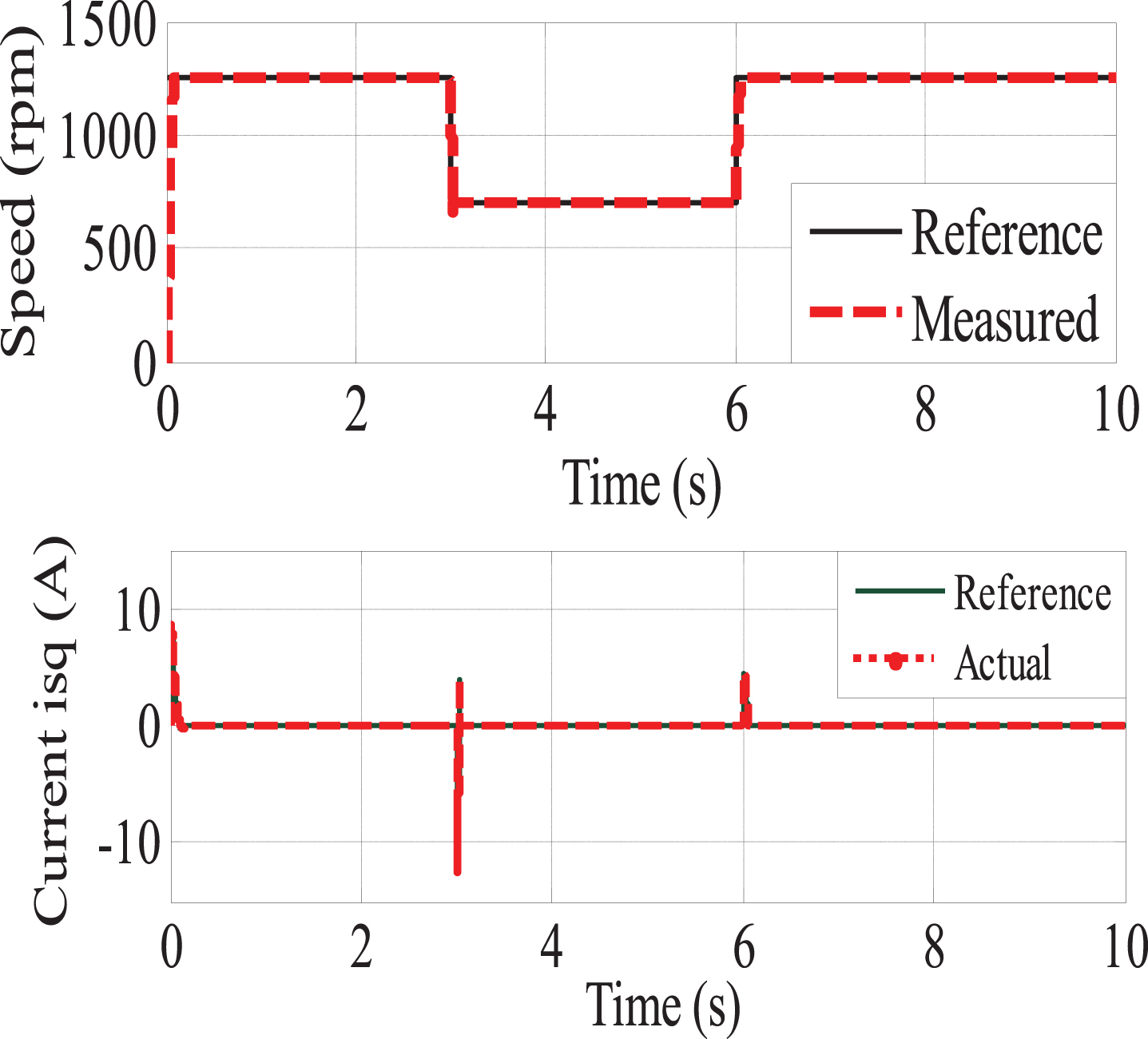
The performance of the proposed control and speed observer in the low speed ranges was verified by providing different speed reference range from zero to 7 rad/s, 2rad/s each step and the triangular speed command, with 50% the load is keep during the operation of the drive for both cases. Figure 9a and b and Fig. 9b show the satisfactory speed tracking performances in both cases. The rotor flux and the estimated speed are quite accurate and matches with reference values. Figure 9a shows that even at a low speed of 1 rad / s and a torque load of 50%, the speed response is very good, the speed ripple in the low range is significantly improved compared to [38, Fig. 3, Fig. 4]. For triangular speed command in both the forward and reverse motoring modes with 50% load, the performance of speed tracking are very good (Fig. 9b). The zoomed in figures show that the estimated and actual speeds follow closely, however, the speed deviation in the case of NNSM_SC_MRAS estimator is less than both estimators, which are proposed in [38, Fig. 4]
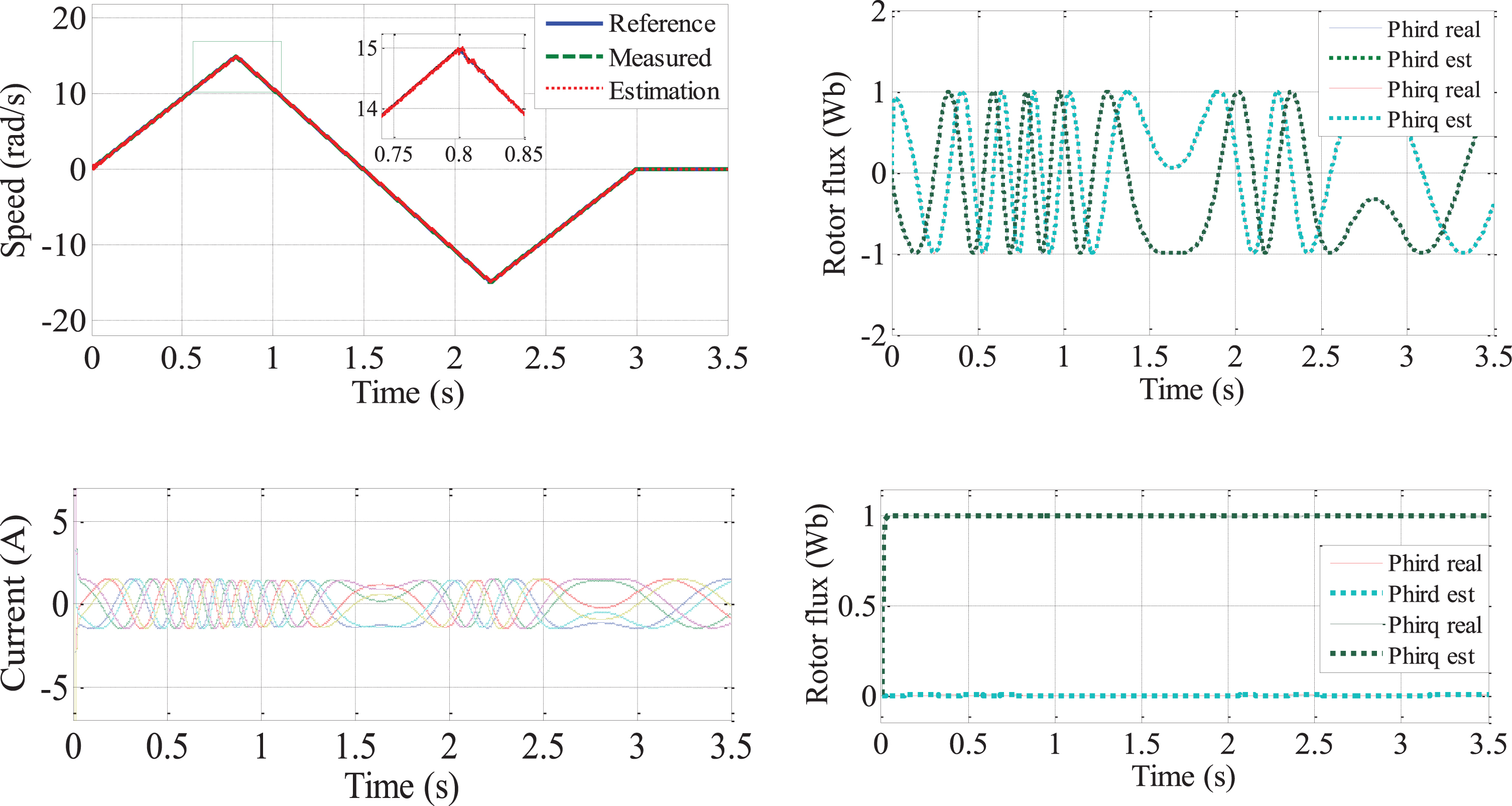
SPIM drive operation in four quadrants.
From the simulation results in Fig. 10, it is easy to see that the speed response and the ability to track according to the reference speed, the estimation errors are well controlled, there is no flux and speed fluctuation in any of the recorded operating modes. The performance of the proposed drive systemt in the four quadrants, which is shown in Fig. 10 is very good.
In all the four quadrants of operation, thee estimated speed follows the real speed which in turn tracks the reference speed, there are no rotor flux and speed ripple in any of the four quadrants of operation recorded.
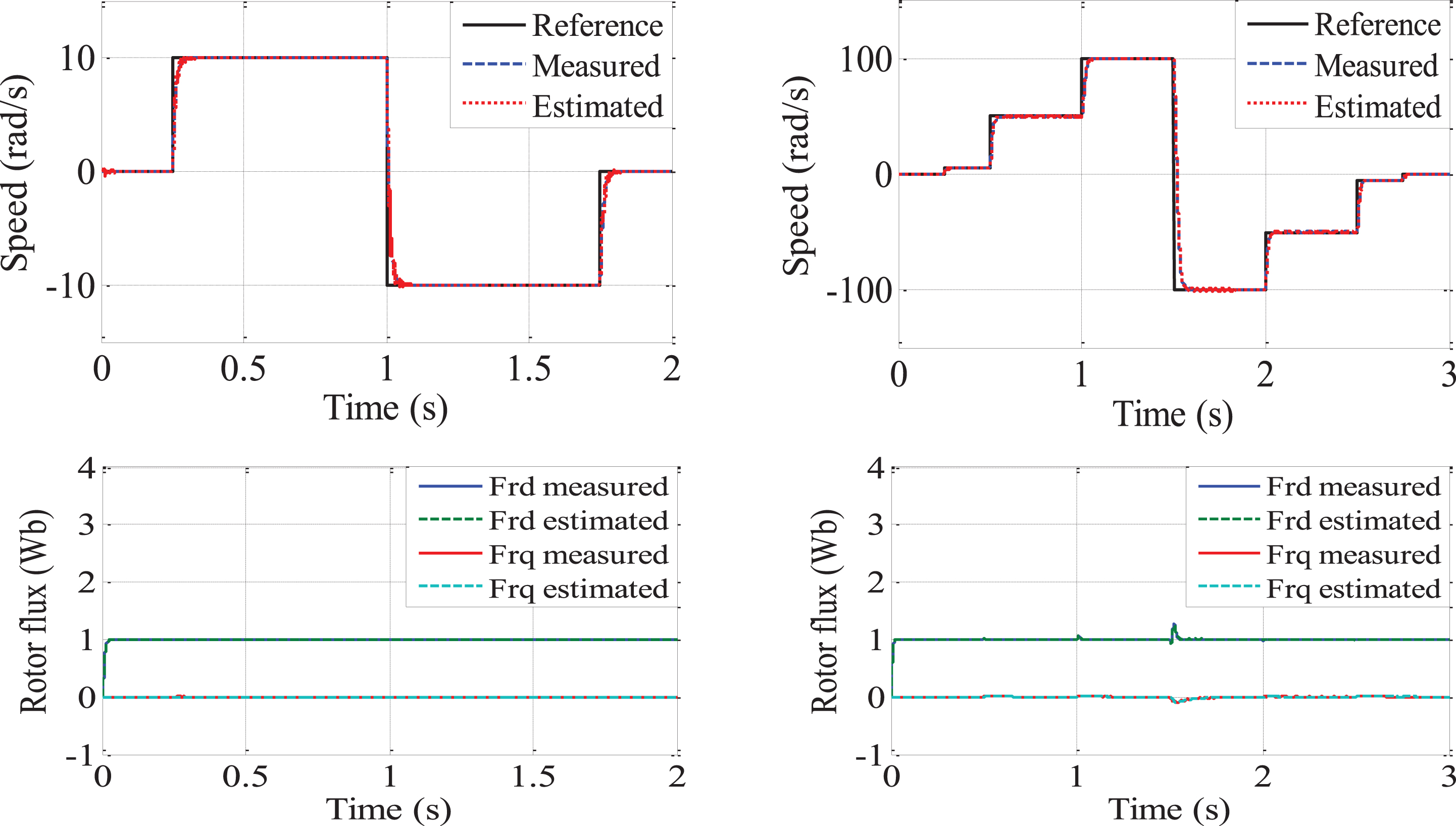
The dynamic performance of sensorless vector control of SPIM drive. (a) The speed reference variations from 0 to 10 rad/s speed reversal –10 rad/s to 50% torque. (b) The speed reference variations from 0 to 5rad/s to 50 rad/s to 100 rad/s to –100 rad/s to –50 rad/s to –5 rad/s to 0.
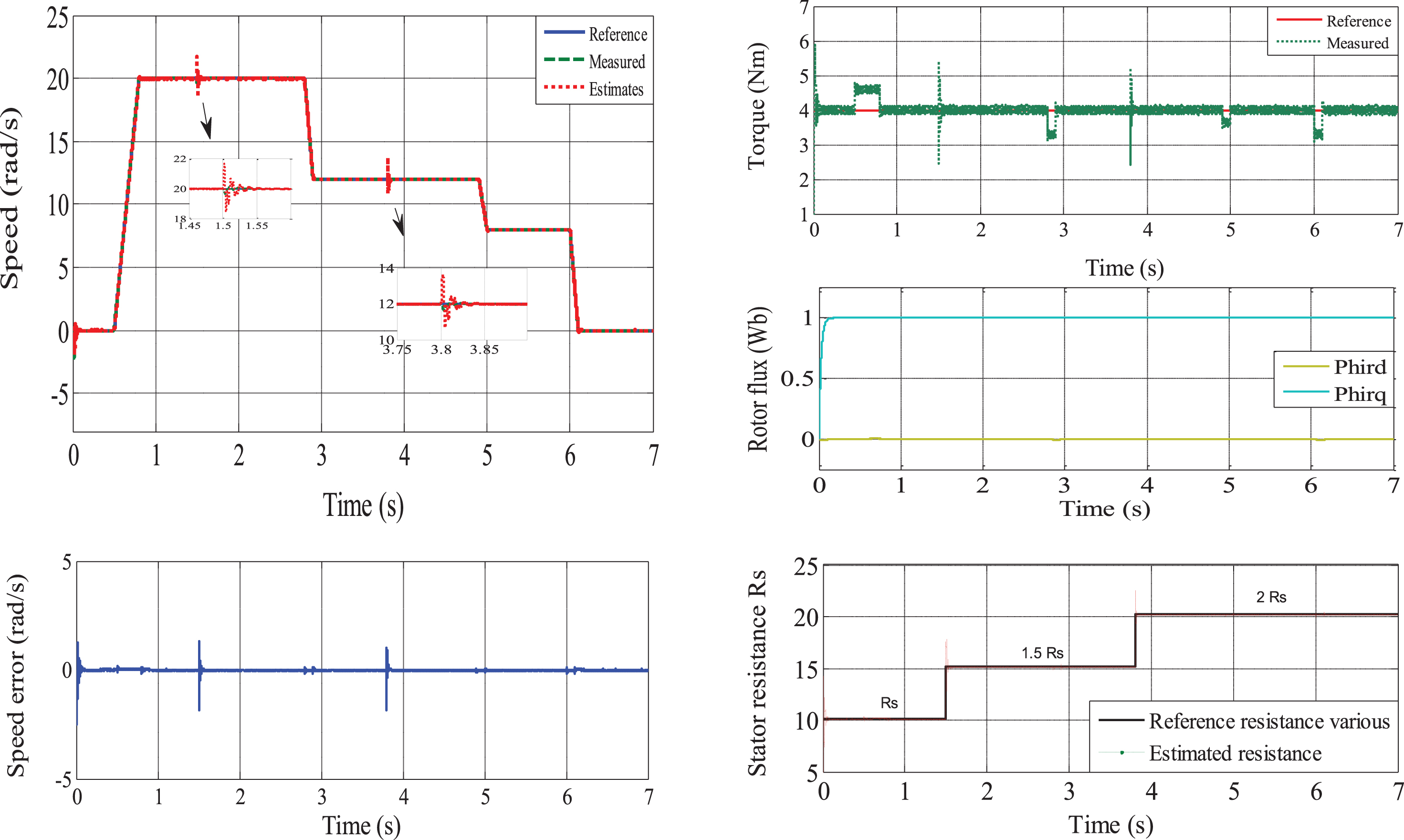
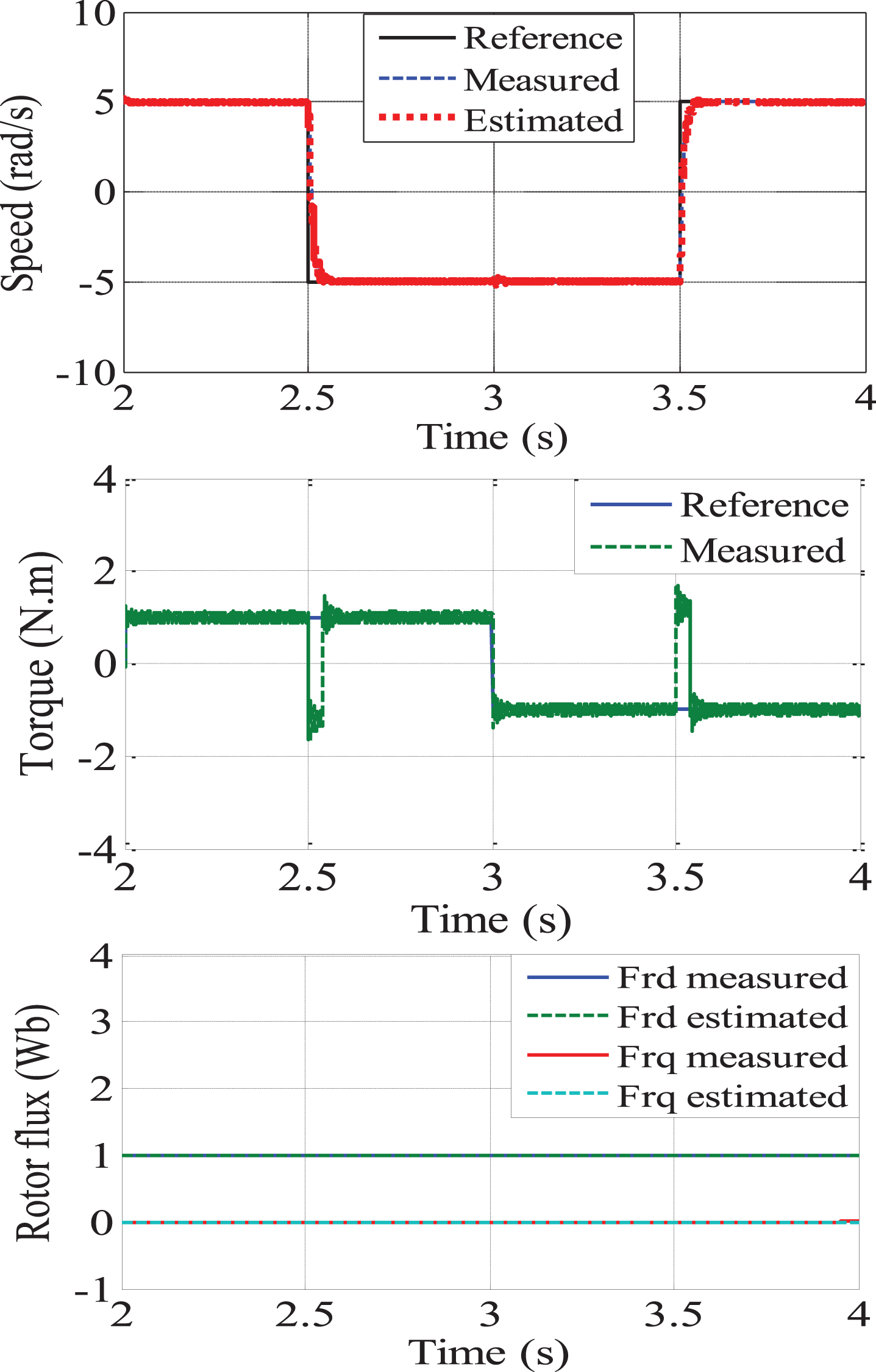
Sensorless control under motor parameter variation condition (Rs).
The dynamic performance of sensorless control of SPIM drive under the speed reference variations from 0 to 100 rad/s speed reversal 0 rad/s to –100 rad/s with 100% load torque at 5 s [10, Fig 11] Test 3].
The dynamic performance survey conducted in both low and high speed ranges is based on [38, Fig. 5]. In both survey cases (Fig. 11) 50 % load is applied. The simulation results show that the dynamic performance of sensorless vector control of SPIM drive are very good, the estimated speed follows the real speed and is close to the reference speed, the estimated efficiency is very good. Similar results are found in both low and high speed cases. Compare with the results obtained in [38, Fig. 5] we can see that the SPIM sensorless control strategy combined BS_PCH controller with NNSM_SC_MRAS observer give better dynamic performance for both high speed and low speed range. Tracking performance, overshoot, transition time are well. This success is partly contributed by the high performance of the NNSM_SC_MRAS estimator. The speed, rotor flux, resistance values are accurately estimated contribute to more improving the performance of the controller and drive system. Figure 11 also shows that the rotor flux is well controlled, stable, oscillation only occurs when sudden in the high speed change (instantaneous change of 200rad/s), the rotor flux oscillation at the reversal point can be observed at 1.5 seconds, but it immediately converges and closely following the reference value, the rotor flux estimate is accurate and follows this change. Compared to the results in [38, Fig. 5] we see that the speed response appears oscillation phenomenon, especially when reversing. The performance at the high speed is worse than low speed range. This is considered by the authors’ efforts to improve excessive low speed. Further, because the controller uses PI controller, in very low range, the control quality is good, but due to the fixed parameters, when changing working areas, other working points, load disturbance,...these controller parameters is difficult to satisfy. In [38], the influence of parameter variations is not considered.
The purpose of this survey is to verify the speed estimation quality of the NNSM_MRAS observer when the motor parameter change. This test is based on bandmark in [45, Fig. 10] but the survey expanded RS value changed 150–200% nominal Rs values at 1.5 s, 3.8 s, respectively. The SPIM drive works with 100% rated load. Figure 12 shows the speed response, estimation error, torque, estimated resistance, rotor flux. The reference speed is increased from 0 to 20 rad/s, then reduced to 12 rad/s to 7 rad/s to 0. The system works stably. The speed ripple and the performance of the tracking the reference speed of the BS_PCH controller and the speed NNSM_ SC_MRAS observer (Fig. 12) are very good with 150% increase in rs. At t = 3.8 s, continues to increase Rs = 200%, the observer still works very well, the estimated error is close to zero, only slightly increases when the increased resistance value and immediately decreases to zero. Observing the simulation results show that the performance of the SPIM drive system is quite good in this cases, the control and parameter estimation strategies give the good responses, sustainably with parameter changes. Simulation results confirm the robustness dynamic performance of the proposed scheme. Indeed, the stator resistance variation does not affect the rotor flux and speed responses. Simulation data shows that the rotor speed is estimated very close to the measured speed. the error between actual speed and estimated speed is very small. In steady state, we can see that the estimated error of rotor speed converges to zero. This shows the good orientation of the rotor flux under the influence of the change of reference speed. The orientations of the rotor flux are ensured even with the change of rotor resistance and these also show the robustness of speed control and estimation strategies.
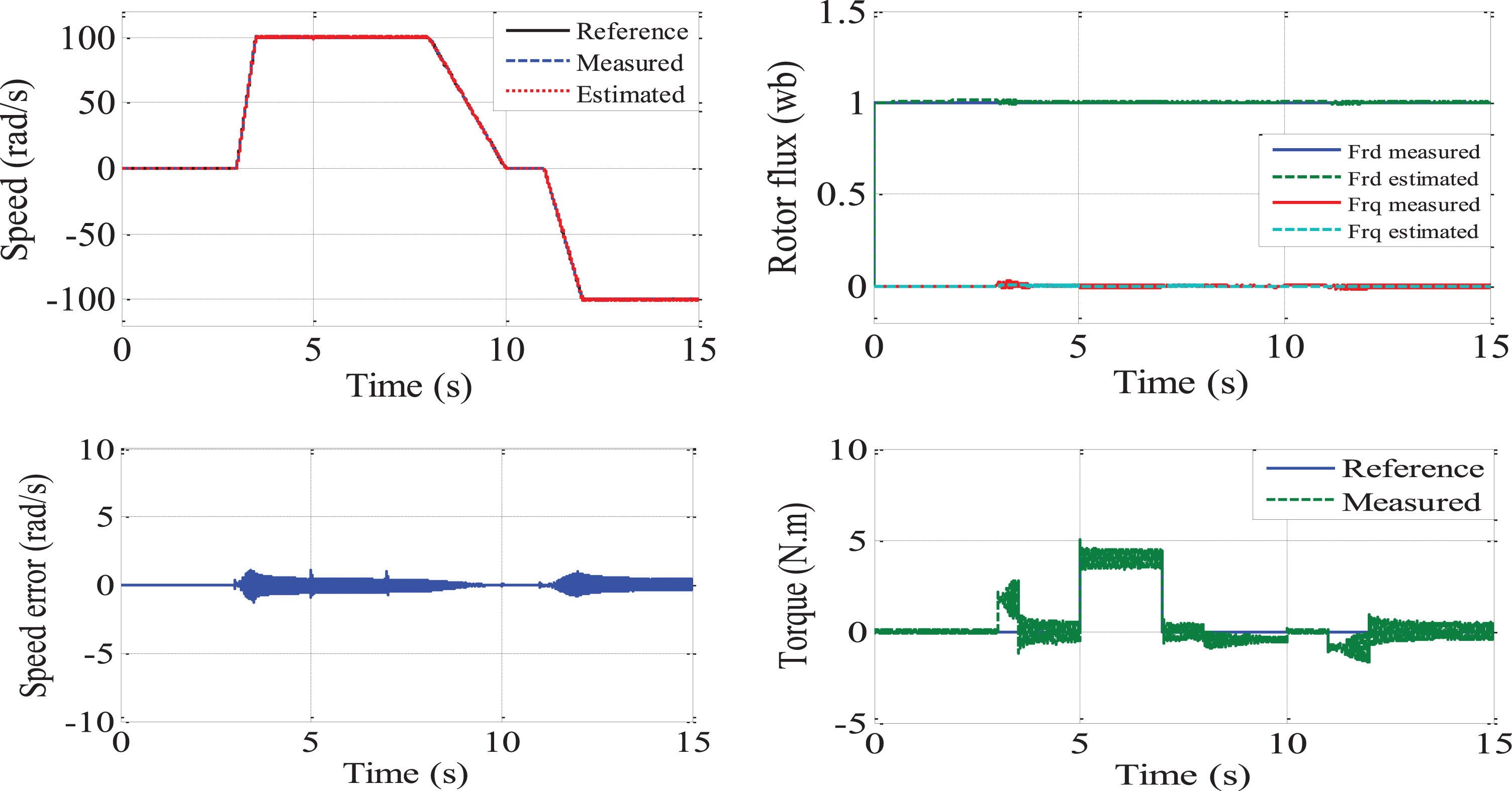
This test make to evalue the load torque disturbance rejection capability of the SPIM sensorless drive and is conducted based on [10, Fig. 11 Test 3]. Figure 13 shows the very good speed, torque, and rotor flux responses when reveral speed at high speed range and load disturbance. In general, load disturbance may affect the motor parameters and increase the nonlinearity level. The proposed scheme has been tested when a rated load torque is applied and rejected at 100 rad/s with 100% load torque. The results show the robust of proposed observer and controller when occuring load disturbance. The NNSM_SC_MRAS given better dynamic performance, the negligible steady and transient state error between the actual and estimated speed as shown in Fig. 13. Furthermore, NNSM_SC_MRAS scheme shows better rotor field orientation performance with isq and isd current components for perfect field orientation. Inaccurate speed and rotor flux estimation causes wrong field orientation for the conventional scheme. In detail, For the proposed scheme the estimated error is less than 1rad/s. Estimated speed follow real speed and always tends to converge with reference speed. Comparing to the results [10, Fig. 11], we see that the dynamic performance of the proposed strategy was quite good in [10]. However, In [10], the torque ripple is reported as in [10, Fig. 9d, 10d, 10d]. Special operating modes are not considered in [10] to make clearer the performance of the proposed strategy (low speed operation, regenerating mode, motor parameter changes larger than 100% nominal values not recorded in [10]).
This paper presents a novel structure combining the PCH and BS nonlinear control for sensorless vector control of SPIM fitted with an adaptive NNSM_SC_MRAS speed observer. The outer speed and flux loop controllers design is based on the BS technique using the integral tracking errors action to improve its robustness. It is different from the research performed on backstepping control with integral action before, the control law used in this proposal does not make the increase of the number of system state so as not increase the complexity of differential equations resolution. Rotor resistance is updated online to BS controller to reduce the effect of parameter variations on the performance of the controller. To enhance more the performance of SPIM drive, PCH scheme is used in the inner current loop controllers. In this proposed PCH current controller, the stabilization of controller is achieved via system passivity. In particular, the interconnection and damping matrix functions of the port-controlled Hamiltonian system are shaped so that the physical (Hamiltonian) system structure is preserved at the closed-loop level and the closed-loop energy function is equal to the difference between the physical energy of the system and the energy supplied by the controller. However, these control techniques can not guarantee good performances without the use of suitable state observer, so the paper give a proposed Stator current based on MRAS observer using neural networks to estimate rotor speed, rotor and stator resistance and rotor flux. The combination of BS_PCH controller with speed estimator can compensate for the uncertainties caused by the machine parameter variations, measurement errors, and external load disturbances, enables very good static and dynamic performance of the sensorless drive system (perfect tuning of the speed reference values, fast response of the motor current and torque, high accuracy of speed regulation) in a wide speed range, and robust for the disturbances of the load, the speed variation and low speed. The simulation results verify the effectiveness of the proposed control and observer.