
Abstract
Most data hiding methods have limitations in resisting cropping and noise attacks. Aiming at this problem, a robust data hiding with multiple backups and optimized reference matrix is proposed in this paper. Specifically, secret data is divided into a set of groups and multiple backups of each group data are generated according to the number of backups. The cover image is divided into several blocks. A reference matrix is constructed by four constraints to assist data hiding and data extraction. The proposed method aims to extract exactly at least one backup of each group data so that the correct backups can construct the secret data well if the stego-image is corrupted. Experimental results show that the proposed algorithm is robust to cropping and noise attacks.
Introduction
Data hiding [1–5], an important research field of data security, aims to embed secret data into the carrier. Compared with encryption algorithm [6, 7], the existence of secret data can be hidden by data hiding methods, so that the secret data is more secure. Generally, data hiding algorithms can be classified into two categories: spatial domain based methods [1–4, 8–18] and transform domain based methods [5, 19–25]. The main advantages of spatial domain steganography are the high embedding capacity and good stego-image quality while transform domain methods do well in resisting a certain degree of attacks.
The existing spatial domain data hiding algorithms can be classified into three categories: The least significant bit (LSB)-based algorithms, pixel-value differencing (PVD)-based algorithms and exploiting modification direction (EMD)-based algorithms. The first categories of algorithms [e.g., 8–10] are well-known data hiding schemes, in which the LSBs of cover image are replaced by secret bits to generate a stego-image. LSB technique has advantages of high payload, good visual imperceptibility, and extreme ease of implementation. But it can be easily detected. The second category of algorithms [e.g., 11–15] calculated the difference between adjacent pixels to determine the quantity of bits that can be embedded into cover pixels. The third category of algorithms [e.g., 4, 16–18] can achieve higher payload and better visual imperceptibility than the former two. Zhang et al. [4] proposed a smart data embedding scheme by exploiting modification direction (EMD) primarily. The binary secret data is transform into the secret digits in the (2n+1)-ary notational system such that n pixels can be used to carry one secret digit. An extraction function is constructed to extract secret data. The later EMD-based algorithms [16–18] endeavor to improve the extraction function so that the performance of data hiding can be improved.
Transform domain methods embed secret data in the transformed coefficients of cover images and satisfy the criteria of imperceptibility and robustness [22]. It is well-known that three are three common signal transform, namely, Discrete Cosine Transform (DCT), Discrete Fourier Transform (DFT), and Discrete Wavelet Transform (DWT). DWT transforms the cover image into 4 main sub bands (LL, HL, LH, and HH). Nag et al. [23] proposed a DWT hiding method in which three LSBs of wavelet coefficients in high-frequency sub-bands are accommodate for secret data. However, data hiding in the HH sub-band is not robust against attacks such as lossy compression. Hemalatha et al. [24] proposed a secure color image steganography integrating Discrete Wavelet Transform (DWT) with Integer Wavelet Transform (IWT). In this method, the cover and secret images are both transformed into DWT sub-bands. The LL sub-bands of both images are divided into disjointed 2×2 blocks. Then, they compared each block in the LL sub-band of the secret image with all blocks of the LL sub-band of the cover image to save the block with the lowest Root Mean Square Error (RMSE). All saved locations of blocks are then generated and embedded into the LSBs of the IWT coefficients of the cover image. Atawneh et al. [25] proposed an efficient embedding algorithm in the DWT domain based on the diamond encoding (DE) scheme. The secret image is first converted into a sequence of base-5 digits. Then, a cover image is transformed into the DWT domain and divided into 2×1 coefficient pairs. Secret based-5 digits are embedded into each coefficient pair by modifying at most one coefficient us DE scheme. In [26], a cover image is transformed into the IWT domain and a 3-dimensional chaotic is used to finding the coordinates of pixels which are used for accommodate secret data. Kumar et al. [27] proposed a modified digital image steganography technique based on DWT. In their method, the cover and secret images are both decomposed into sub-images using DWT. These sub-images are partitioned into non-overlapping blocks. The blocks of sub-images of secret image are match with the blocks of sub-images of secret image using root mean square method. The best matched blocks are embedded into the other sub-images of cover image. Zhang et al. [28] presents a data hiding method using multidirectional line encoding (MDLE) and (IWT). IWT is used to achieve accurate extraction of secret bits. The four sub-bands are divided into non-overlapping coefficient blocks sized 3×3. The center coefficient of the block is paired with surrounding coefficients in eight directions to embed n-bit secret data, respectively.
Although the above transform domain methods achieve the robustness for a certain degree of attacks, they are not good at resisting cropping with large area and noise with high density. In order to further improve data security, an optimized reference matrix is constructed. Several backups of secret data are embedded into the cover image according to this optimized reference matrix to decrease the possibility that all the backups of one group are corrupted. The proposed scheme can resist cropping and noise attacks. The rest of the paper is organized as follows. Section 2 presents the proposed method. Section 3 provides experimental results and the robustness of the proposed method. Finally, this paper is concluded in Section 4.
Proposed method
In this paper, secret data is divided into a set of groups and each group data is copied to generate multiple backups according to the number of backups firstly. Then a cover image is selected and divided into several block to accommodate multiple backups of secret data. The last but not the least, the reference matrix is constructed via restrictions. According to the reference matrix, multiple backups of secret data are embedded into the cover image using LSB replacement technique.
Cover image selection
In order to accommodate multi-backup of secret data, it is necessary to confirm the size of the cover image firstly. Assume that S is secret data sized L and is divided into n groups. n backups of each group are generated and meanwhile each secret bit has n backups. Suppose the y-th backup of the x-th group data is sx,y (1≤x≤n, 1≤y≤n). Then the size of each group is calculated as following.
In Equation (1), ⌊⌋ and mod denote rounding down operation and modulo operation, respectively. Consequently, if 1≤y≤r, s x ,y contains l + 1 bits secret data, otherwise sx,y contains l bits secret data. Suppose that sx,y,z is the z-th bit of sx,y. If 1≤y≤r, 1≤z≤l+1. Otherwise, 1≤z≤l.
After n backups of n groups of secret data are obtained, the cover image is divided into n×n non-overlapping blocks. In this paper, a backup of a group data is embedded into the h LSBs of each pixel in a block using LSB replacement technique. Let K×K be the minimum size of the block which accommodates a backup of a group data completely, K is given by Equation (2).
If N = n×K, a cover image sized N×N at least is needed to accommodate n backups of secret data. Our multi-backup data hiding aims to extract exactly at least one backup of each group of data so that the correct backups can construct the secret data well if the stego-image is corrupted.
As described in the Section 2.1, the selected cover image is divided into n×n non-overlapping blocks sized K×K and each block is denoted by
In Equation (3), pi,j is the value of the i th row and the j th column in
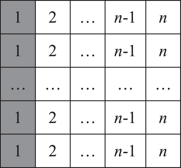
A reference matrix
It is observed that each row of
The reference matrix is determined by four constrains which are (1) the size of area that contains 1,2,..,n, (2) the relationship of between the current value with its 8 neighbor values, (3) the number of the same values on the line of the reference matrix. (4) the sum of Euclidean distances of the same values, respectively. These four constrains are illustrated as following.
Firstly, in order to ensure n backups of each group are evenly distributed during data hiding, assume that
Secondly, if n≥8, the each value of reference matrix should be different from its 8 neighbor values to ensure that the n backups of a group of data are not adjacent. Assuming that
In Equation (4), -1≤h’≤1, -1≤k’≤1.
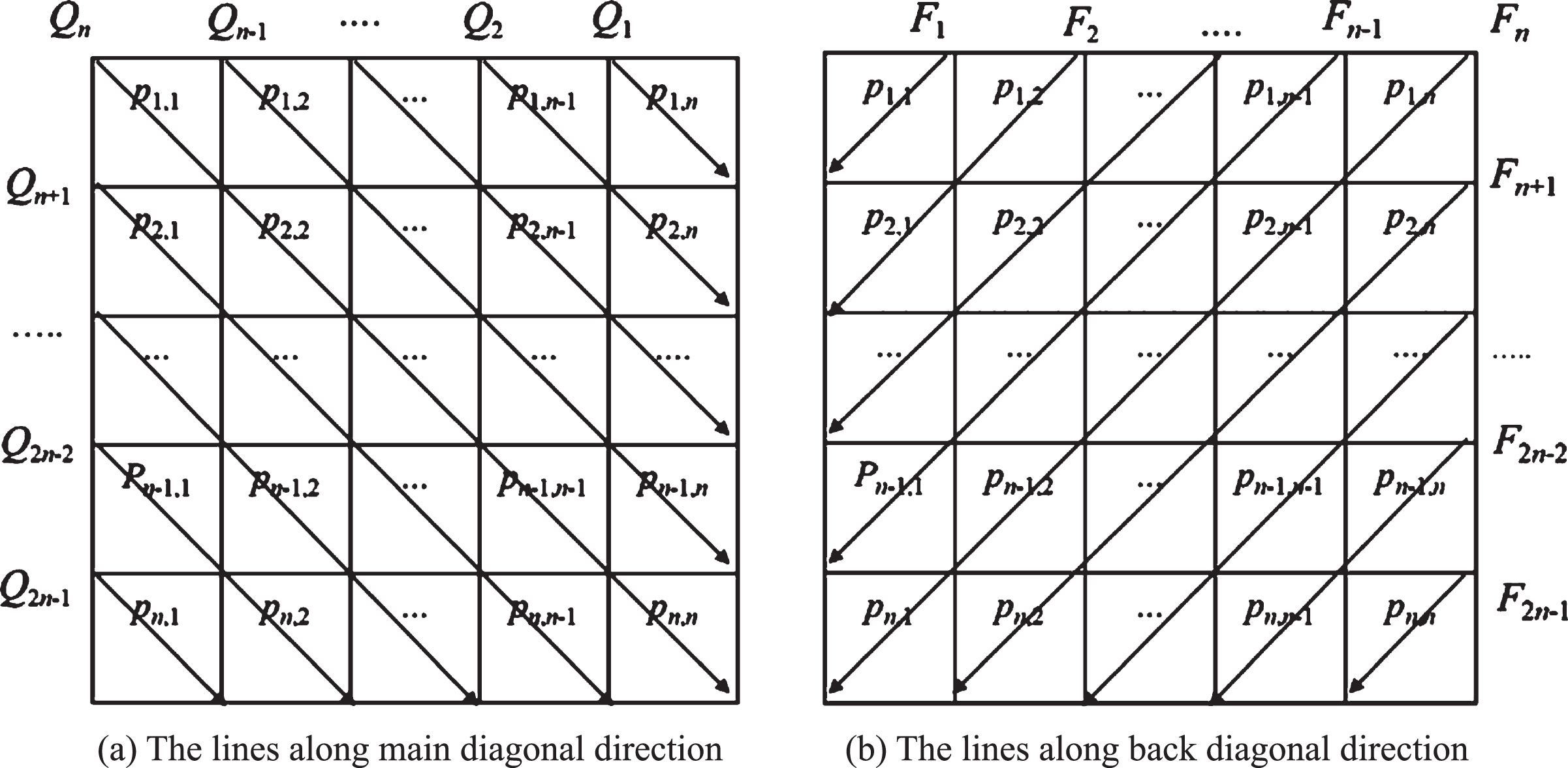
Thirdly, in our paper, the lines of reference matrix consist of the lines along horizontal direction (the rows), the lines along vertical direction (the columns), the lines along main diagonal direction and the lines along back diagonal direction as shown in Fig. 2, respectively.
The oblique lines along main diagonal direction and back diagonal direction.
For the ith row p
i
,1, p
i
,2, ... ,pi,n, the number of the values, which are equal with x, is given by Equations (5) and (6).
Since 1≤i≤n,1≤x≤n, the most number of the same values among all the rows is given by Equation (7).
For the j th column p1,j, p2,j, ... , p
n
,j, the number of the values, which are equal with x, is given by Equations (8) and (9).
Since 1≤j≤n,1≤x≤n, the most number of the same values among all the columns is given by Equation (10).
There are 2n-1 oblique lines along main diagonal direction in the Fig. 2 (a). The sets of the values on these lines are denoted by Q1, Q2, ... , Q2n - 1 and they are given by Equation (11).
Then the number of the values, which are equal with x, is given by Equations (12) and (13).
Since 1≤r≤2n-1,1≤x≤n, the most number of the same values among the oblique lines along main diagonal direction is given by Equation (14).
Also, there are 2n-1 oblique lines along back diagonal direction in the Fig. 2 (b). The sets of the values on these lines are denoted by F1, F2, ... , F2n - 1 and they are given by Equation. (15).
Then the number of the values, which are equal with x, is given by Equations (16) and (17).
Since 1≤r≤2n-1,1≤x≤n, the most number of the same values among the oblique lines along back diagonal direction is given by Equation (18).
Consequently, the numbers of same values in the lines along different directions are subject to Equation (19).
Where T1 and T2 are two threshold values. Fourthly, since n backups of the x-th group data are embedded into the blocks with p
i
,j=x, the farther distance among same values in the reference matrix is, namely the farther distance among n backups of a group data is, the stronger the anti-cropping and anti-noise ability of the stego image is. Suppose that the reference matrixes are z1,z2, ... , z
m
which are subject to the previous three constrains. In z
l
(l = 1,2, ... ,m), let the coordinates of all the x be
Then the sum of Euclidean distances among all the x (x = 1,2, ... ,n) in the reference matrix z
l
can be calculated by Equation (21).
Assume d k = max(d1,d2, ... , d m ), where k is the index of d k . Consequently, z k is selected as the reference matrix and the secret data is embedded into the cover image according to z k .
Different reference matrixs can be obtained with different values of T1 and T2. A reference matrix with T1 = 1, T2 = 2 and n = 8 is shown in Fig. 3(a) and another reference matrix with parameters T1 = 2, T2 = 3 and n = 8 is shown in Fig. 3(b). As shown in Fig. 3(a), the values in the each row and column are different and the most number of same values along the oblique lines is 2. As shown in Fig. 3(b), the most number of same values among the rows and columns is 2 and the most number of same values along the oblique lines is 3. Therefore, the same values in Fig. 3(a) are more uniformly distributed than those in Fig. 3(b). Consequently, the reference matrix of Fig. 3(a) is more suited to assist multi-backup data hiding than the one of Fig. 3(b).

n = 8, the reference matrixes with different T1 and T2.
With the number of backups increasing, the size of the reference matrix also increases. Figure 4 shows a reference matrix with n = 10, T1 = 1 and T2 = 3. In this reference matrix, the values which are located in the each row or column are different. Any 4×4 region contains 1,2,...,n, and any value is different from its 8 neighbor values. The most number of the same elements on the oblique lines is 3.
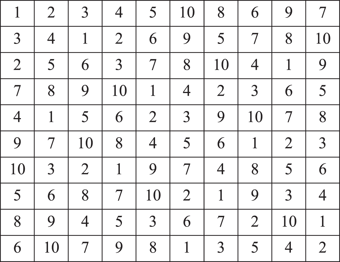
Reference matrix with T1 = 1, T2 = 3, n = 10.
It is noted that if T1 = 1 and T2 is optional, the reference matrix is a Latin square matrix. A Latin square of order n is an n×n array filled with a set of n distinctive symbol elements, where each symbol appears exactly once in each row and each column. Lei et al. [26] selected the Latin square matrix with n = 8 as shown in Fig. 5 as a reference matrix. It is observed that the most number of the same elements on the oblique line is 4 in Fig. 5 and there are some 3×3 regions which do not contain 1,2,..,8, as the dark regions show. This reference matrix is not enough robust for noise and cropping. Consequently, T2 is seted to improve the robustness and Fig. 3(a) is an excellent reference matrix with T1 = 1 and T2 = 2. The most number of same values along the oblique lines is 2 and any 3×3 region contains 1,2, ... ,8. The reference matrix as shown in Fig. 3(a) is superior than the reference matrix as shown in Fig. 5.
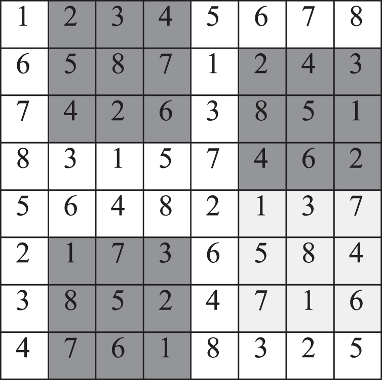
Reference matrix from [26].
The secret data is divided into n groups and n backups of each group are generated. The cover image is selected and divided into n×n non-overlapping blocks. Then a reference matrix
Step 1: The secret data sized L is divided into n groups and the size of each group is calculated. n backups of each group are generated and the y-th backup of the x-th group data is denoted by s x ,y (1≤x≤n, 1≤y≤n).
Step 2: The cover image is selected according to Section 2.1 and is divided into n×n non-overlapping blocks, denoted by
Step 3: A reference matrix
Step 4: x = 1, y = 1, i = 1, j = 1;
Step 5: If pi,j=x, sx,y is embedded into the h LSBs of the pixels in
Step 6: x = x+1. If x > n, go to Step 8; else go to Step 7.
Step 7: If j < n, j = j + 1, goto Step 5; else j = 1, i = i + 1, goto Step 5;
Step 8: If y < n, y = y + 1, x = 1, i = 1, j = 1, goto Step 5; else go to Step 9;
Step 9: Stop. Then L, n,
Data extraction
If the stego image is corrupted by cropping or noise, the backups of secret data can be extracted to recover the secret data. After the receiver obtains a corrupted stego-image, he or she can extract the uncorrupted backups of each secret bit according to the data-hiding key which contains the size of the secret data L, the number of backups n, the reference matrix
By the same way, n backups of a secret bit can be extracted, denoted by {sx,1,z, sx,2,z, ... , sx,n,z} from the blocks with pi,j=x. If mx,y,z=1, sx,y,z is also corrupted. Otherwise, sx,y,z is uncorrupted and can be used for constituting secret data.
Consequently, secret data {1,1, s1,2, ... , s1,l +1, ... , sr,1, sr,2, ... , sr,l +1, sr +1,1, sr +1,2, ... , sr +1,l, sn,1,sn,2, ... , s n,l } can be obtained the above method. Where l and r can be calculated by Equation (1).
In order to validate our performances, several experimental results are carried out in this section. A 8-bit grayscale Lena image sized 64×64 is selected as a secret image as shown in Fig. 6(a) and each pixel of the secret image is transformed into 8 bits of data to generate secret data sized 32768 bits. In this paper, the backup number is 8. The size of the payload is 262144 bits and the 1 LSB of the cover image pixel is used for embedding data. Consequently, a 8-bit grayscale Baboon image sized 512×512 is selected as the cover image, as shown in Fig. 6(b). According to the reference matrix as shown in Fig. 3(a), 8 backups of secret data are embedded into the cover image to obtain a stego-image as shown in Fig. 6(c). Section 3.1 presents the performance of anti-cropping, Section 3.2 presents the performance of anti-noise.

Secret image, Cover image and Stego-image.
If the stego-image is cropped, secret data is extracted from the cropped stego-image according the reference matrix. The extracted secret data is evaluated by the bit correct ratio BCR [27], which is given by Equation (25).
In this paper, the maximum cropping areas of several cropping modes are calculated under BCR = 100%. The cropping modes are: The stego-image is corrupted with vertical cropping, as shown in Fig. 7(a). The stego-image is corrupted with horizontal cropping, as shown in Fig. 7(b). The stego-image is corrupted with circle cropping, as shown in Fig. 7(c). The stego-image is corrupted with rectangular cropping, as shown in Fig. 7(d). The stego-image is corrupted with diagonal cropping, as shown in Fig. 7(e).
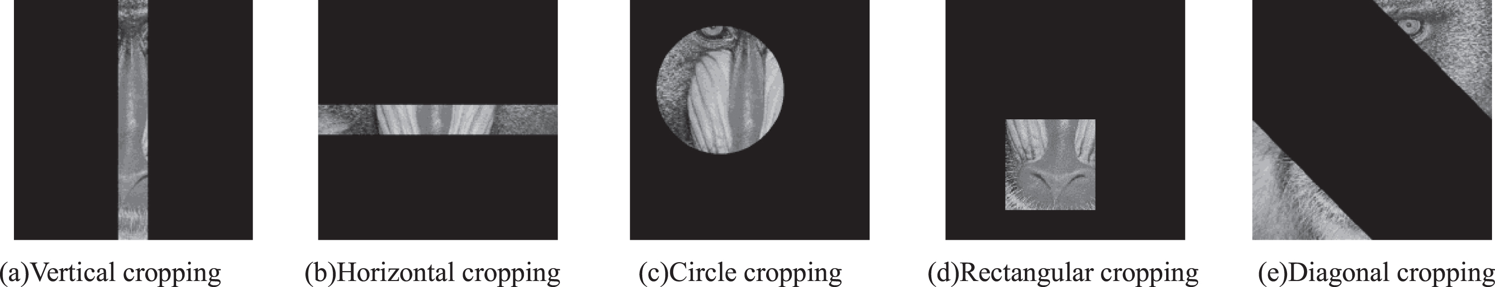
Different Cropping modes with BCR = 100%.
Table 1 illustrates the percentages of the maximum cropping areas under several cropping modes as shown in Fig. 7. It is obvious that our method achieve superior anti-cropping performance.
The percentages of the maximum cropping areas when BCR = 100%
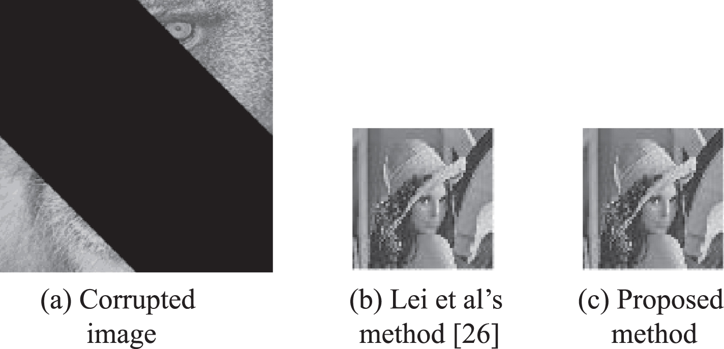
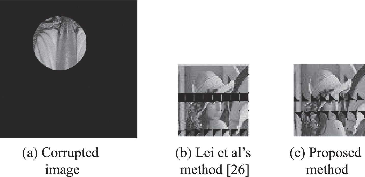
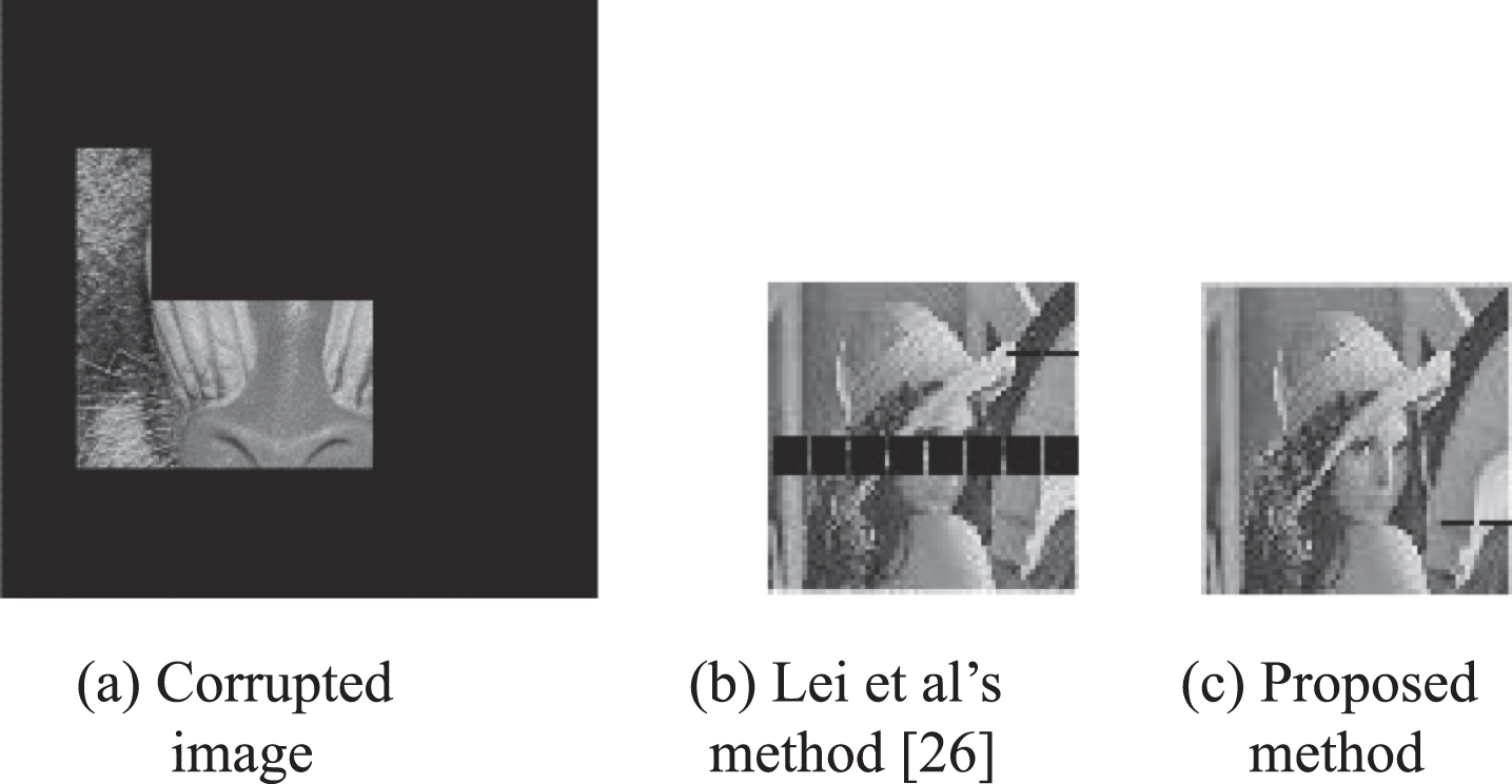
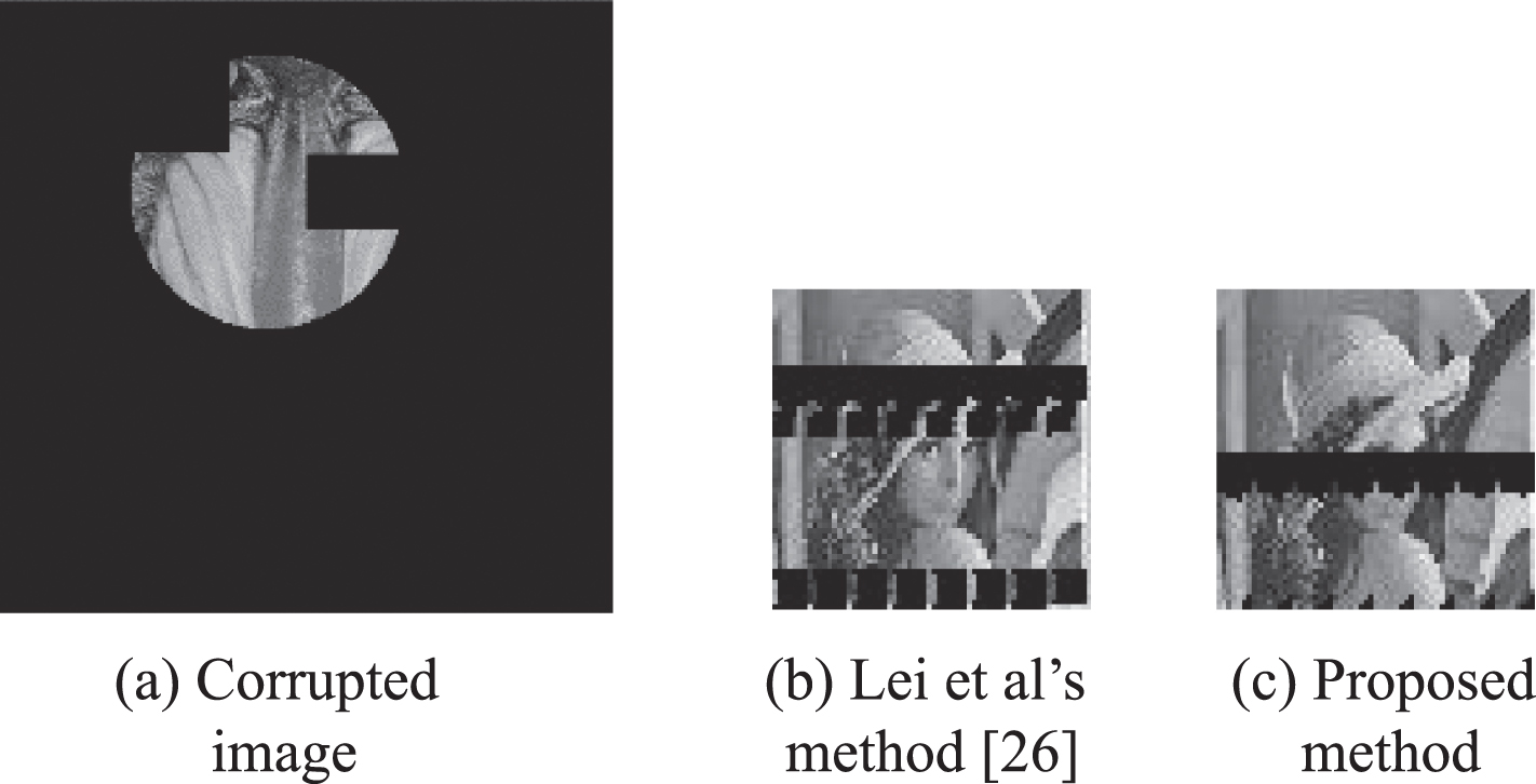
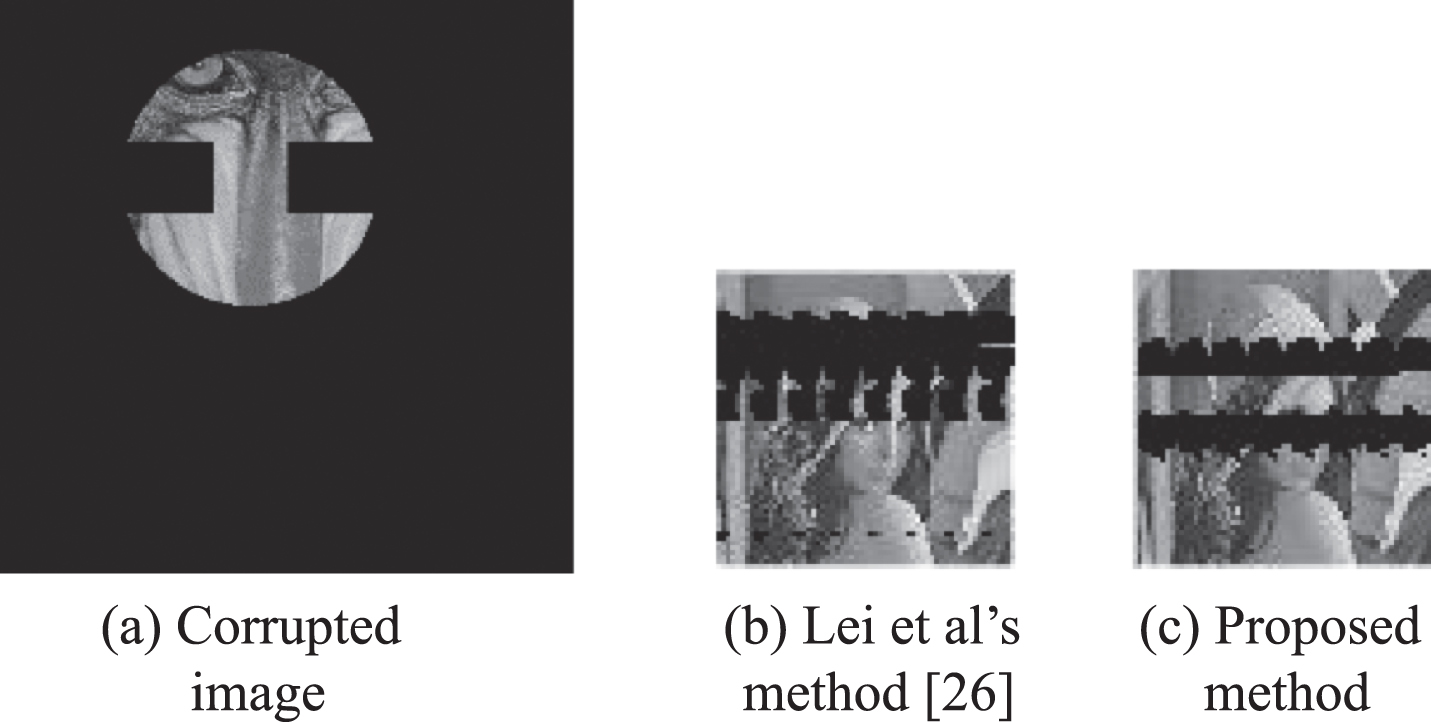
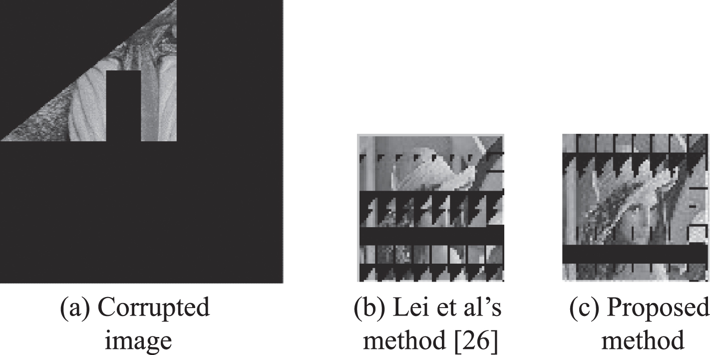
A large number of experiments have been carried out on free large-area cropping, and all the extracted secret images have achieved good performance. Table 2 illustrates BCR comparison results between Lei et al’s method [26] and proposed method under different cropping modes with different percentages of the cropping areas. These different cropping modes are shown in Fig. 8(a)∼23(a), respectively. It is observed from Table 2 that if the stego-image is corrupted by vertical cropping with 87.5%, Horizontal cropping with 87.5% or diagonal cropping, 75%, the secret image can be extracted without errors using Lei et al’s method [26] and the propose method. But if the stego-image is corrupted by circle cropping with 84.43% or rectangular cropping with 85.94%, the secret image cannot be extracted without errors using Lei et al’s method [26], while the secret image can be extracted perfectly using the proposed method. Also, BCRs of the secret images which are extracted using our method are higher than those of the secret images which are extracted using Lei et al’s method [26] in case of other cropping modes as shown in the Table 2. Figs. 8–23 demonstrate the extracted secret images using our method have better visual quality than the extracted secret images using Lei et al’s method [26] in case of BCR < 100%.
BCR comparisons of extracted secret image between Lei et al’s method [26] and the proposed method
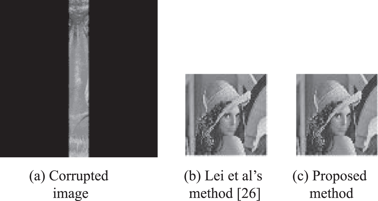
Vertical cropping with 87.5%.
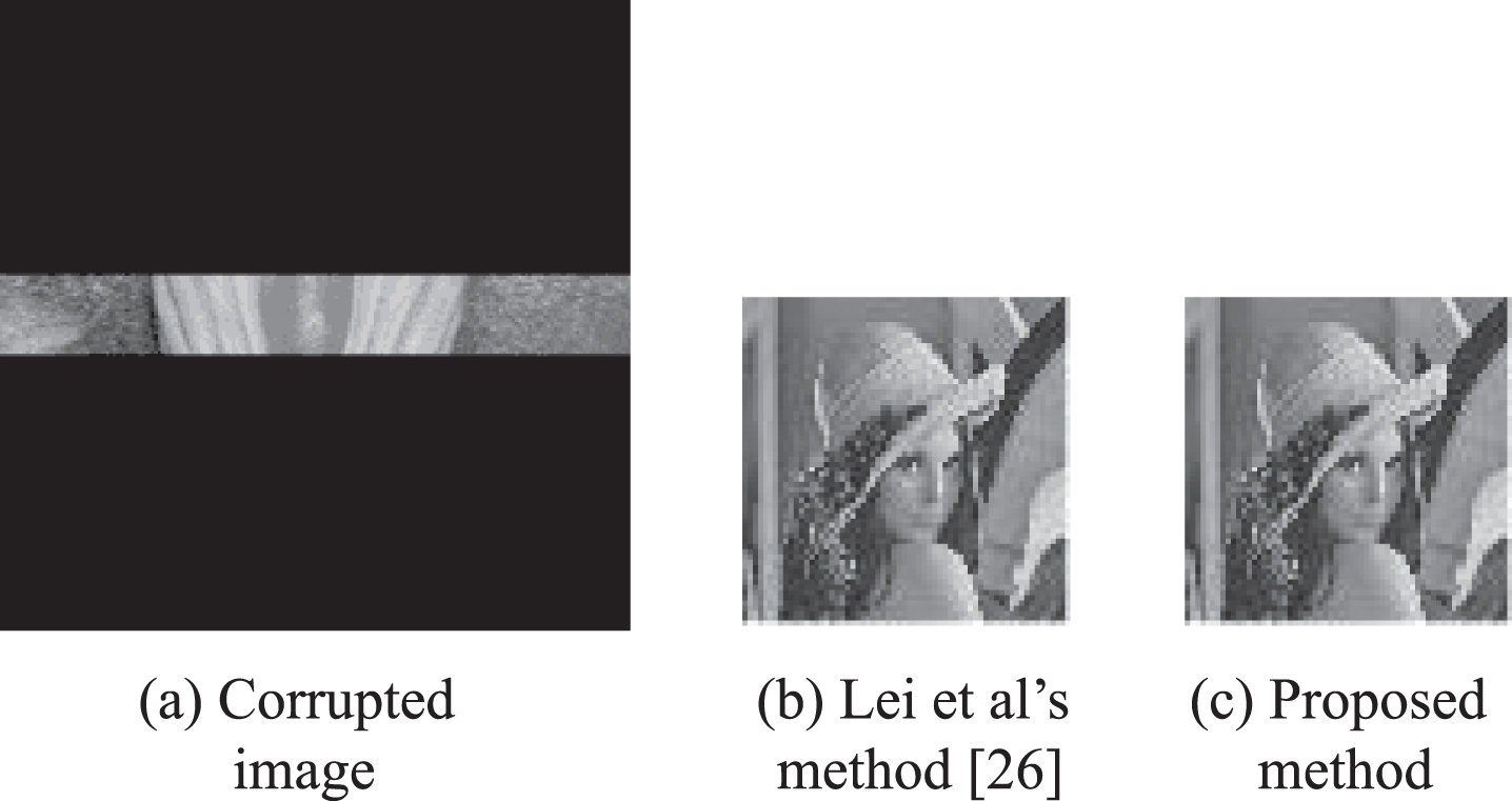
Horizontal cropping with 87.5%.
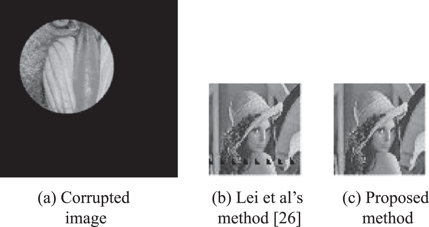
Circle cropping with 84.43%.

Rectangular cropping with 85.94%.
Diagonal cropping with 75%.

Random out-of-circle cropping with 85.5 %.
Random out-of-circle cropping with 88.02 %.

Random rectangular cropping with 86.08%.

Random rectangular cropping with 86.23%.
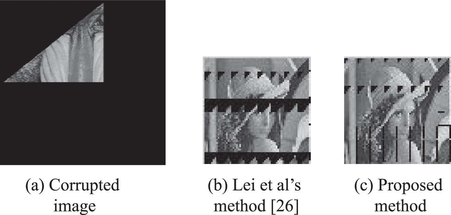
Random triangle cropping with 85.34%.
Free cropping with 84.38%.
Free cropping 85.4%.
Free cropping with 87.43%.
Free cropping with 88.5%.
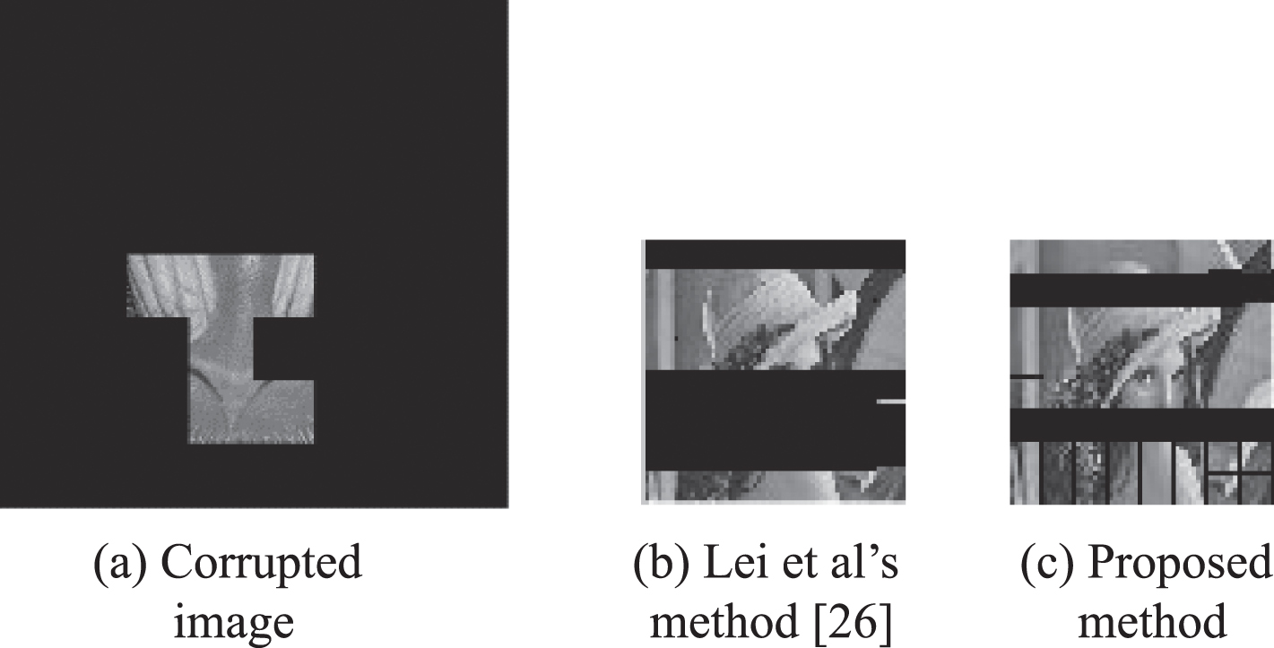
Free cropping with 90.63%.

Free cropping with 92.19%.
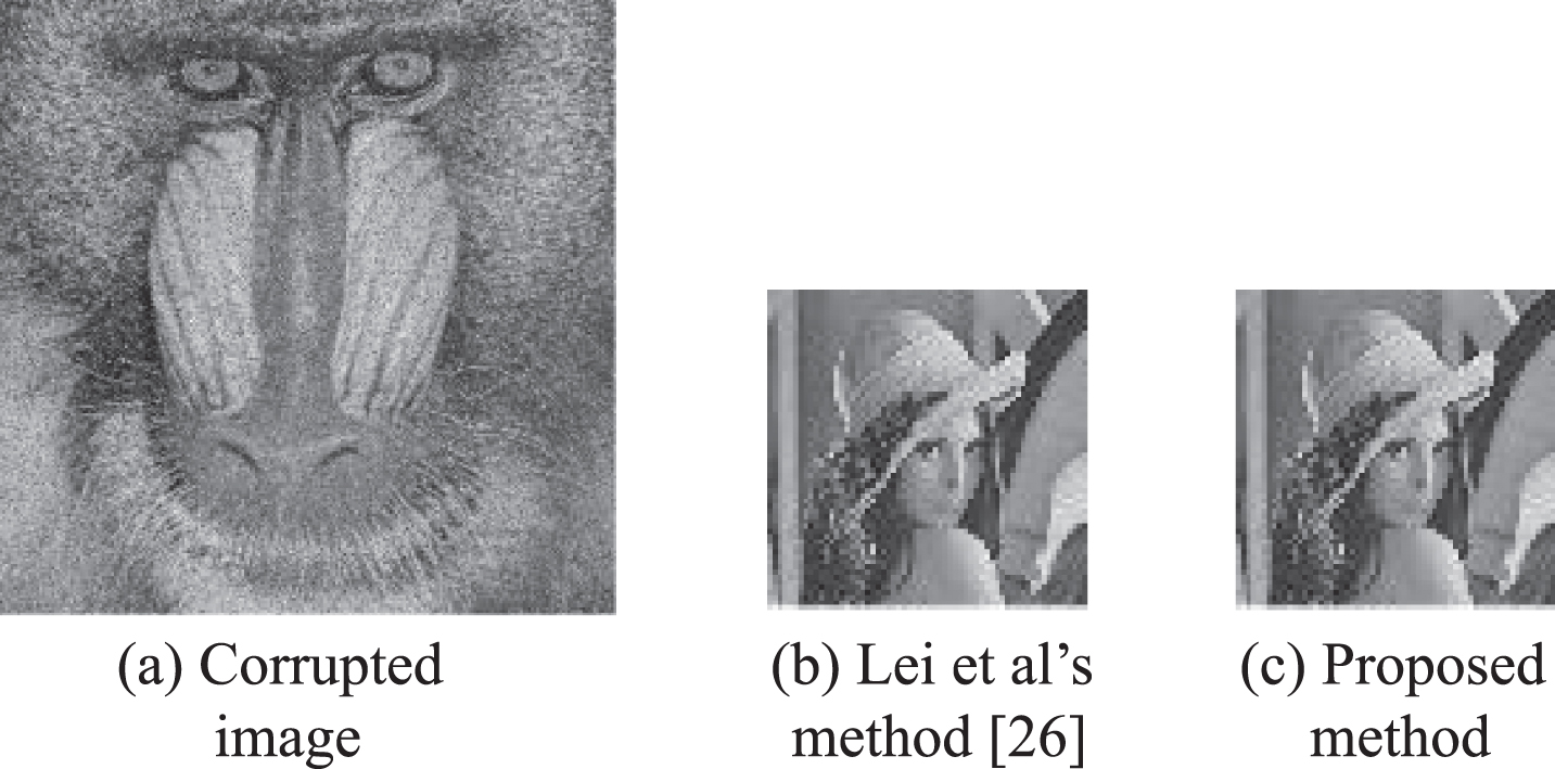
If the stego-image is corrupted by pepper and salt noise, secret data can also be extracted from the corrupted stego-image. The extracted secret image is evaluated using peak signal-to-noise ratio PSNR, which is given by Equation (26).
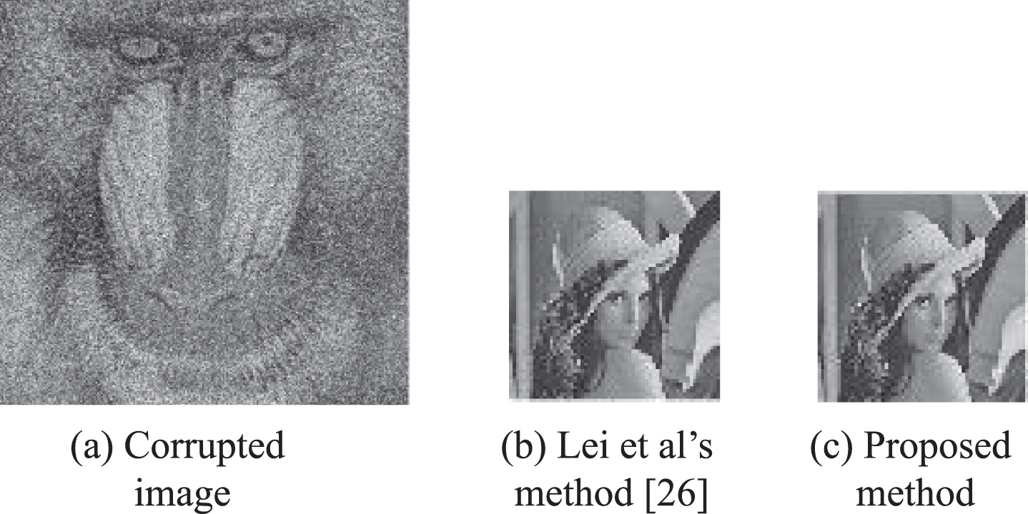
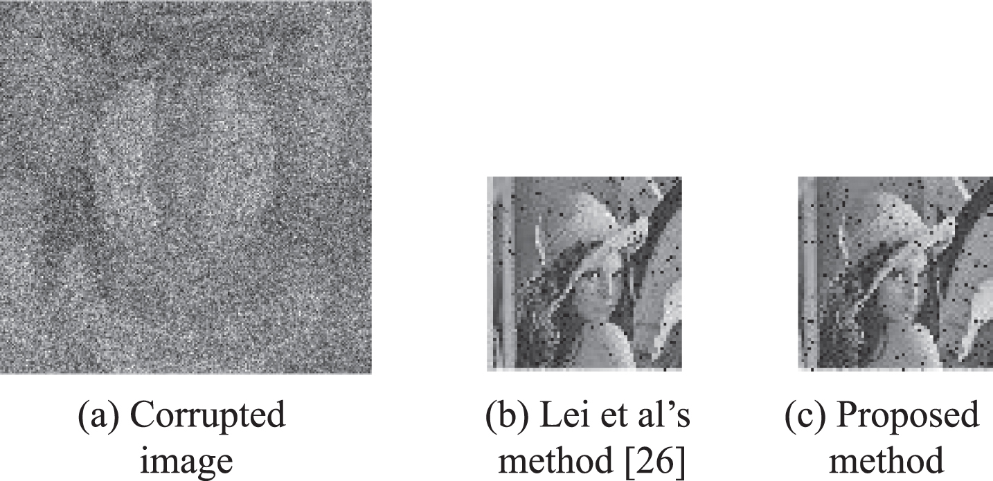
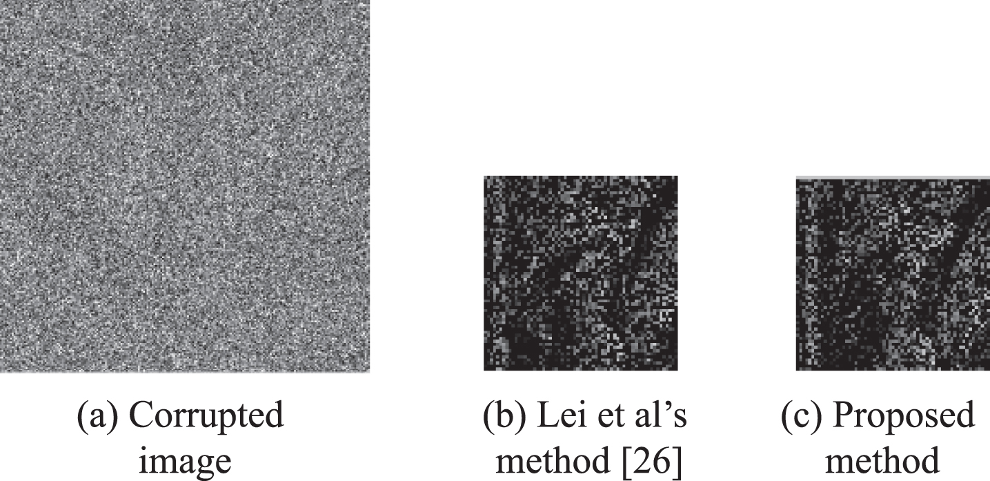
The higher PSNR is, the less loss of extracted secret image obtains, and Inf represents the secret image can be extracted without errors. Table 3 and Figs. 24–32 illustrate the PSNR and visual quality comparisons between the proposed method and [26] under different noise intensities, respectively. It is observed that the proposed method outperforms [26] when noise intensity is less or equal with 0.4. When noise intensity exceed 0.4, the proposed method underperforms [26] slightly.
PSNRs of the extracted secret images under different noise intensity

Noise density with 0.1.
Noise density with 0.2.
Noise density with 0.3.

Noise density with 0.4.

Noise density with 0.5.
Noise density with 0.6.

Noise density with 0.7

Noise density with 0.8.
Noise density with 0.9.
In short, the performance of anti-noise in our method is satisfactory.
In this paper, a robust data hiding with multiple backups and optimized reference matrix has been proposed. Secret data is divided into a set of groups and multiple backups of each group data are generated according to the number of backups. Then an optimized reference matrix is constructed. According to this optimized reference matrix, multiple backups of every group data can be embedded into the different image blocks evenly to generate a stego-image. This can debase the possibility of destroying all the backups of one group data in case that the stego-image is corrupted. If a backup of each group data is extracted without errors so that secret data can be obtained perfectly according the reference matrix. The use of the reference matrix has brought about the excellent performance of anti-cropping and anti-noise in our paper. As well, experimental results demonstrate that our proposed method has superior performance compared with Lei et al’s method [26] with regard to anti-cropping and anti-noise.
Data availability
The images used to support the findings of this study are included within the article.
Conflicts of interest
The authors declare that there is no conflict of interest regarding the publication of this paper.
Footnotes
Acknowledgments
This work was supported by the National Natural Science Foundation of China (61762017, 61562007, 61363034, 81701780), Guangxi “Bagui Scholar” Teams for Innovation and Research, the Guangxi Natural Science Foundation (2017GXNSFAA198222, 2015GXNSFDA139040, 2017GXNSFBA198221), the Project of Guangxi Science and Technology (GuiKeAD17195062), the Project of the Guangxi Key Lab of Multi-source Information Mining & Security (16-A-02-02, 15-A-02-02), and Guangxi Colleges and Universities Key Laboratory of cloud computing and complex systems (15202).