
Abstract
In the current industrial production process, waste heat of low quality is seriously wasted. In order to effectively recover low-quality waste heat, the research group developed a small energy conversion device –Roots power machine. On this basis, the research group designed a low-quality waste heat efficient utilization system with the equipment as the core and successfully applied it to low-quality waste heat recovery. However, in the actual operation process, the system can not run stably due to the occasional fluctuation of the input gas source. In view of this, after the study of waste heat recovery system, the fluctuation of gas source can be controlled by different grades according to the degree of change. Fuzzy rules also divide variables into different grades to solve problems, and fuzzy control can convert continuous changes of airflow into discrete changes, which greatly reduces the complexity of the control system. Therefore, the research group proposed a control strategy based on fuzzy PID. The simulation results show that the adjustment time of fuzzy PID is within 7 s, and the adjustment effect is obviously better than that of traditional PID. The experimental results show that the speed deviation under the condition of air source fluctuation is within the speed fluctuation rate (±5%), and the speed deviation under the condition of sudden disturbance load is within the steady speed adjustment rate (±3.5%), both of which meet the requirements of indexes. Therefore, the fuzzy PID control strategy can further improve the stability of output speed, reduce airflow pulsation, and provide the possibility for grid-connected power generation.
Introduction
In the process of industrial production, a large amount of industrial waste heat is directly discharged into the air, resulting in a huge waste of resources. Nowadays, various industries have related industrial waste heat recovery technologies, but these technologies are aimed at waste heat resources with relatively high temperature and pressure and low recovery difficulty. Low-quality waste heat is waste heat gas with a temperature lower than 160°C and a pressure lower than 0.8 Mpa. A large part of low-quality waste heat resources are wasted due to the relatively low energy contained in it and the difficulty in recovery [1]. At present, the recovery of low-quality waste heat requires that the waste heat recovery equipment has the characteristics of miniaturization and lightweight. The equipment that can be used for low-quality waste heat recovery is mainly the screw expander, but the processing precision of the key parts of the equipment is very high and the cost is high. Therefore, based on the screw expander, the research group developed a small Roots power machine by improving its mechanical structure. The equipment is smaller in volume, more convenient in processing, more flexible in application and more suitable for recovery of low quality waste heat. The main purpose of waste heat recovery is power generation. When the waste heat recovery system solves the problem of power generation stability, it is possible to realize grid-connected power generation in the future. In this way, waste heat from conventional fuels and technologies can be effectively addressed, greatly improving energy efficiency.
Research on low-quality waste heat recovery technology is conducive to comprehensive conservation and efficient use of resources, and promotes the development of low-carbon recycling. In addition, combining with the characteristics of waste heat recovery system to study reasonable control algorithm to improve the response speed of the system, the design of a stable and efficient control system will play a very important role in the stable operation of the waste heat recovery system, and provide a new technical direction for energy conservation and emission reduction.
Fang Haiyan et al. analyzed the utilization status of waste heat resources in industrial production of glass kilns. In order to make more effective use of low-temperature waste heat to reduce energy consumption of glass kilns, flue gas from glass kiln boiler was used as heat source to establish a low-temperature organic Rankine cycle device model and realize the recovery and utilization of low-temperature waste heat in glass kilns by using organic Rankine cycle. However, the recovery device lacks accurate control system, so it is difficult to realize efficient utilization of waste heat [2]. Kosmadakis George and Neofytou Panagiotis extended the existing thermodynamic model of the organic Rankine cycle and considered adding nanoparticles to the refrigerant. The results showed that the efficiency of the organic Rankine cycle increased as the mass fraction of nanoparticles increased. At the same time, nanoparticles also affect the heat transfer and pressure drop of organic fluids in the circulating system, which need to be optimized by the control system [3]. Jaume Fito and Sacha Hodencq et al. optimized the temperature of the recovered waste heat and the capacity of the heat storage device, and optimized the flow of waste heat by the control system to improve the recovery rate of waste heat and enhance the stability of the system [4]. In the organic Rankine cycle, Toyota uses the eddy power machine to recover the waste heat in the system, which greatly improves the efficiency of fuel utilization. It can be seen from the experimental results that the equipment has a higher recovery efficiency when the experimental environment is close to room temperature [5]. Quoilin et al. established a low-temperature organic Rankine cycle model for scroll expander, and verified the correctness and feasibility of the model through experiments [6, 7]. Lemort et al. analyzed the main factors affecting its performance£¬according to the established model of scroll expander [8]. The scroll expander can effectively improve the recovery efficiency of waste heat, but the cost of the equipment is high, and the general control system is difficult to meet the control accuracy. Toffolo used the hybrid method of genetic algorithm and sequential quadratic programming to design the organic Rankine cycle without restriction in the superstructure, increasing its stability [9]. Low-quality waste heat recovery device contains multiple sensors work together, Xu Gongguo in multisensor scenarios presented a multi sensor scheduling method oriented to collaborative detection and tracking, the method is based on some considerable markov decision process to build sensor scheduling model, can implement multi-sensor resources reasonable scheduling [10]. Wen Zhang et al. adopted a closed-loop PI control method in the internal combustion engine waste heat recovery system. The results of the World Coordinated Transition Cycle (WHTC) show that the closed-loop PI control has a shorter response time and better tracking ability in the dynamic process [11]. Pang Kuo Cheng et al. used a simulation platform to compare the VFD control strategy of the Organic Rankine Cycle and the pump curve control strategy. The results obtained show that under different heat conditions, the two control strategies have different effective ranges [12]. These control methods can effectively recover heat energy, but they are not stable enough.
There are two gaps in these researches on waste heat recovery. On the one hand, these researches mainly focus on the waste heat resources with high temperature, which have large equipment and high cost; On the other hand, these researches are weak in the design of control system, and the stability of the system can not be guaranteed. To solve these problems, the research group designed a low-quality waste heat efficient utilization system with Roots power machine as the core component. The system can effectively recover low-quality waste heat and has the characteristics of low cost and high heat recovery efficiency. One of the common means of waste heat recovery and utilization is to generate electricity, and the operation of the generator needs the stable speed provided by Roots power machine. When the gas source fluctuates, it is necessary to adjust the gas flow in the pipeline to ensure the stability of the output speed. In the process of using the traditional PID algorithm to control this device, due to the characteristics of the traditional PID itself, the air flow in the pipeline will be repeatedly adjusted based on the set value, resulting in the pulsating characteristics of the air flow sometimes being large and sometimes small. This situation will not only produce noise, but also seriously affect the stability of the output speed, reduce the use value, need to be solved.
Traditional PID control method signal processing is too simple, and the differential signal of the error generation method is not good enough. In the traditional PID control, the function of error integral feedback is to eliminate the static error and improve the accuracy of system response, but at the same time, the introduction of error integral feedback makes the closed loop dull, prone to oscillation and produce pulsating airflow. According to the system’s requirements of response speed, regulation time and overshot, fuzzy PID control strategy is introduced. Fuzzy PID does not depend entirely on pure mathematical model, but on fuzzy rules. Fuzzy PID has the following advantages: 1. The use of language is convenient and does not require precise mathematical models; 2. Strong robustness, suitable for solving nonlinear, strong coupling, hysteresis and other problems in process control; 3. Strong fault-tolerant ability. Therefore, fuzzy PID is more suitable for the control of low-quality waste heat recovery and utilization system. In this paper, a fuzzy PID control strategy is established and verified by simulation and experiment. Compared with traditional PID control, the fuzzy PID control algorithm can effectively eliminate the influence of external interference on the speed, so as to realize the stable recovery and utilization of low-quality waste heat.
Composition and coupling model of low-quality waste heat efficient utilization system
The low-quality waste heat efficient utilization system is shown in Fig. 1. The system is composed of waste heat recovery system and circulation system. In the system, filter device is used to filter the dust and particles in the low-quality waste heat gas, improve the quality of the waste heat gas entering the evaporator, and thereby improve the waste heat recovery efficiency. Among them, the Roots power machine uses a dual-intake Roots power machine, the purpose is to make the Roots power machine work stably.

Low-quality waste heat utilization system.
The system is suitable for the recovery of low-quality waste heat, that is, the temperature is less than 160°C, the pressure is less than 0.8 MPa of industrial flue gas and steam, usually is directly discharged industrial waste heat waste gas without pollution. Waste heat gas enters the system through the inlet of the evaporator. After the heat transfer, it is discharged by the outlet of the evaporator.
Part of the circulatory system adopts organic Rankine cycle for waste heat recovery and energy conversion. The circulating working fluid of the organic Rankine cycle is organic matter with low boiling point and high vapor pressure, which can improve the recovery efficiency. At the same time, the organic Rankine cycle does not need to remove the wet vapor in the working fluid, and can also prevent the equipment from being oxidized to a certain extent [13, 14].
The organic working medium steam in the gas storage tank is separated by the valve, and one part enters the Roots power machine smoothly through the air inlet, and then enters the auxiliary heat device, and the other part directly enters the auxiliary heat device. The auxiliary heat device can recover part of the heat energy of the organic working medium before condensation and reduce the waste of heat energy. The air inlet and the air outlet of Roots power machine are respectively installed with sensor groups, which are used to detect the pressure, temperature and flow parameters of the air inlet and the air outlet. In order to ensure that the Roots power machine can perform work smoothly, it is necessary to adjust the opening and closing degree of the electric valve of the air inlet of the Roots power machine according to the measured parameters to adjust the air intake volume. Recycled waste heat is used to drive rotating machinery to do work, or directly to generate electricity. Suitable for generators with rated power below 100 kW (determined according to the gas flow per unit time), the generator selected in this paper has rated power of 10 kW and speed of 300 r/min.
The control system of waste heat recovery aims at maintaining the constant speed of the output shaft of Roots power machine. Speed is affected by a number of factors. The coupling relationship of some variables in waste heat recovery process is shown in Fig. 2.
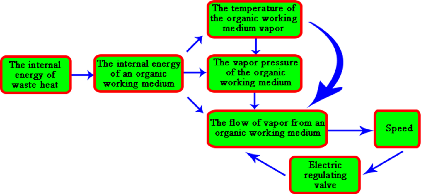
System coupling relation.
The heat source temperature of low-quality waste heat is relatively low, and the regulating valve of the waste heat recovery system part needs to be fully opened, so that the evaporator can have a relatively high heat recovery efficiency. The circulation system regulates the flow of the organic working medium steam through the electric control valve, so that it can meet the needs of Roots power machine to output stable speed. The flow rate of organic working medium vapor is influenced by its temperature and pressure, and the temperature also influences the pressure, which makes the parameters in the system have strong coupling. The output end of Roots power machine has a speed acquisition device, which forms feedback regulation through the speed measurement, and regulates the flow through the electric control valve to maintain the constant speed of the system. According to the performance analysis of the whole system, the rotation speed fluctuation rate of Roots power machine should be within –5%∼5%, and the stable time of rotation speed should be within 7 s [15, 16].
This system adopts fuzzy PID control algorithm to control the speed of low-quality waste heat efficient utilization system. The system controls the flow of organic working medium steam into Roots power machine by controlling the opening and closing degree of electric control valve, so as to make Roots power machine stable work output stable speed. The electric control valve is mainly controlled by speed feedback, and the adjustment results are compensated by temperature and pressure. The regulating block diagram of the system is shown in Fig. 3.
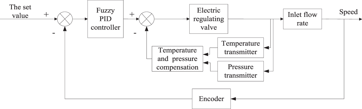
Block diagram of system regulation.
(1) Characteristics of electric control valve
The electric control valve is controlled by the controller in real time, and then the steam flow is controlled. Its transfer function is approximately expressed as:
In this formula: Q (s) —The Laplace transform of steam flow through an electric regulator; V (s) —The Laplace transform of electric control valve input signal; K1 —The amplification factor of the valve; T1 —The time constant of the valve.
When the electric control valve controls the flow, the value of K1 is:
In this formula: Δ (Q/Qmax) —The change value of relative steam flow that can be adjusted by electric control valve; Δ (A/Amax) —The variation range of the relative opening of the electric control valve; ΔV —Range of electric control valve input signal.
(2) Characteristics of Roots power machine
Roots power machine is a rotating hydrodynamic machine driven by water steam, and its physical model belongs to a volumetric steam turbine [17, 18]. Its simplified physical model is shown in Fig. 4.

Simplified model of Roots power machine.
According to the energy equation, air inlet:
The continuous equation (quasi-steady state) and the rotor motion equation are as follows:
The flow characteristic equation of critical state and non-critical state can be expressed as:
In these formulas: N, η —Power and efficiency of Roots power machine; T, P, h —Temperature, pressure, enthalpy; s, g —Roots power machine, loads (e.g. generators); in, out —The inlet and outlet of Roots power machine.
According to the fluid continuity equation:
The rotor motion equation is as follows:
The equation of motion is:
Take the Laplace transform and get:
In this formula: ξ n (s) —The change of rotor angular velocity; ξ p (s) —Pressure change; b —External load disturbance; d —Unequal rate; J —Rotary inertia of Roots power machine; K —Valve opening, T0 —Volume time constant; T a —Rotor flying time constant, T s —Time constant; M T —The principal moment of Roots power machine; M e —The resistance moment of Roots power machine.
If G2 (s) is defined as the transfer function of the Roots power machine, then:
(3) Characteristics of speed collector
An encoder is used as a speed collector to detect the output speed of Roots power machine when it works. By counting the pulses in each period, the current measured velocity information can be expressed. The encoder information can be expressed by the following formula:
In these formulas: δ is the encoder pulse equivalent; N is the fine fraction of the shaft scale of the encoder; w is the angular velocity of the measured axis; n is the number of pulses; T is the pulse counting period.
Without considering processing delay and electrical signal error, it can be considered that the encoder can reproduce the angular velocity of Roots power machine output axis without loss. The transfer function of the encoder can be expressed as follows:
In this formula: P (s) is the coder line number coefficient; θ (s) is the rotation Angle function of the output axis; and the transfer function of the encoder can be obtained through calculation as a time-independent constant.
The rotation speed regulation channel of Roots power machine can be represented by a linear combination of the second-order hysteresis model, and the transfer function of the second-order hysteresis model can be expressed as:
In these formulas: T1 and T2 are oscillation periods; τ is the process hysteresis time constant; K is the steady-state gain coefficient of the process;
According to the above mechanism, a simple system model was established, and the transfer function of Roots power machine speed regulation system was calculated as follows:
In these formulas: Y is the output shaft speed of Roots power machine; G is the rotational speed adjustment control model of Roots power machine; u is the output signal of the fuzzy PID controller with rotation speed deviation [19, 20].
When the shape of the membership function curve is slow, the output change caused by input is not so drastic, and the control characteristics are gentle, with good system stability, and it is not easy to produce the pulsation of airflow. In the low-quality waste heat power generation speed regulation system, the expert experience method is used to preliminarily determine the rough membership function according to the actual experience of the experts, and then modify and improve it through “learning” and practice test. Therefore, the membership function of each variable is set as trapezoidal curve, which has low resolution and good stability. The basic field of speed deviation e is [–21, 21], and the basic field of speed deviation change rate ec is [–1.3, 1.3]. The opening value of the electric control valve is 0–100, which is converted into a value of 0–1.0 through standardized treatment. The numerical expression of input and output variables can be obtained by normalization of the fuzzy domain. The output shaft speed deviation e of Roots power machine is [–4, 4], and the rate of change of speed deviation ec is [–4, 4]. The table of fuzzy rules is shown in Table 1.
Fuzzy rules for KP, KI and KD speed regulation
Fuzzy rules for KP, KI and KD speed regulation
The real-time data of K
P
, K
I
and K
D
can be obtained by referring to the fuzzy control rule table. The PID parameter value formula at time K is as follows:
Based on the above formula, PID parameter values at time K are calculated to obtain the controlled object control quantity:
Output formula of continuous PID control:
In this formula: K p is the proportional part gain; T i is the time constant of the integral part; T d is the time constant of the differential element. Laplace transform is applied to both sides of Equation (28) to obtain the transfer function as follows:
In this formula: U (s) and E (s) are respectively The Laplace transform of the input and output of PID controller; K P is proportional gain; K I is integral gain; K D is the differential gain. According to the transfer function, the simulation model of Roots power machine output regulation system is established.
In the PID control system adjustment process of Roots power machine, the PID parameters K p , K i and K d need to be adjusted to achieve good control effect. The other parameters should be determined according to the actual production operation and relevant reference materials: T1= 1 s, T2= 0.6 s, T3= 0.4 s, V= 0.016 Mpa/s, τ1= 0.44 s, τ2= 0.4 s, K1= 0.2. In MATLAB, the root locus function rlocus and rlocfind command were used to determine K p , K i and K d according to the Ziegler-Nichols critical proportional coefficient method. The Ziegler-Nichols PID parameter setting table was shown in Table 2. K k was the passing gain and T k was the critical oscillation period of the system [21].
Ziegler-Nichols PID parameter tuning table
The locus formed by the roots of the characteristic equation in the complex plane as some parameter changes from zero to infinity is called the root locus. The root locus method is intuitive. By using the root locus of the system, the stability and transient response characteristics of the closed-loop system with known structure and parameters can be analyzed, and the influence of parameter changes on the system performance can be analyzed. In the low quality waste heat recovery control system, adjustable parameters and the position of open loop pole zero of the system can be determined according to the requirements of the system performance indexes, which can be used for the analysis and synthesis of the system. In the process of PID parameter tuning, the critical value of the characteristic equation can be solved according to the transfer function, and then the PID parameters can be calculated. The root locus obtained by calculation is shown in Fig. 5.
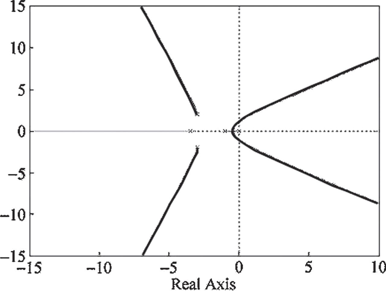
PID controller root trajectory.
When the critical stable angular frequency is 0.0460, the three PID parameters are: K p = 3.0086, K i = 4.8847e-005, K d = 7.7118e-006.
Simulation
In order to test the regulating effect of the fuzzy PID controller on roots power machine speed in the low-quality waste heat efficient utilization system, Matlab software was selected as the platform to compare and analyze the control results of the fuzzy PID controller and the traditional PID controller [22, 23]. In the speed regulation system, the PID initial parameters K P = 1.9, K I = 2.6 and K D = 0.1 were determined, and experiment on increasing and reducing disturbance load. The simulation results are shown in Fig. 6. In the figure: the blue line P—the adjustment effect under PID control; the red line N—the adjustment effect under fuzzy PID control.
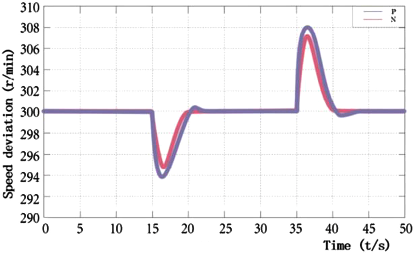
Simulation results under disturbance load.
The expected speed was set as 300 r/min, and the disturbance load was suddenly increased at 15 s and decreased at 35 s. The change of the speed and the adjustment time were shown in Table 3.
Speed regulator under disturbance load
The simulation results show that when the rotating speed changes, the adjusting time of the fuzzy PID is obviously better than that of the traditional PID, and the overshoot is not obvious, and the flow pulsation is not easy to appear.
The debugging equipment of the low-quality waste heat efficient utilization system is shown in Fig. 7. The red circle on the right in the picture is the control box with a circuit board inside, and the red circle on the left is the control panel. The touch screen is installed on the control panel as the main control method.

Low-quality waste heat efficient utilization system debugging equipment.
The control system of the low-quality waste heat efficient utilization system takes the STM32F103 microcontroller as the core controller, and the hardware platform of the control system is shown in Fig. 8. The terminals, switch input module and relay output module on the hardware platform are used for information acquisition and control signal output. The platform contains a variety of communication interfaces to facilitate communication with other devices.

The hardware platform of the control system.
The touch screen is developed by MCGS, and the communication between the touch screen and the control system constitutes the man-machine interaction system. The interface of the man-machine interaction system is shown in Fig. 9. In the figure, (a) is the control interface, which can set the output speed and reduction ratio, and check the air inlet and outlet parameters of Roots power machine. (b) Is a real-time display interface, which can display the changes of parameters in the form of curves.

The man-machine interaction system.
In the process of experimental debugging, direct steam source supply was adopted. The main debugging link was to use the steam source to push the rotation of Roots power machine, and to impose fluctuations on the gas source and load respectively, so as to collect the rotational speed data of Roots power machine.
1. Analysis of experimental data under fluctuating gas source
Gas source fluctuations are simulated by fine-tuning the manual valve. Ten speed data in the interval of 2 seconds in this state are selected to calculate the speed deviation. The data is shown in Table 4.
The rotation speed in the state of gas source fluctuation
The rotation speed in the state of gas source fluctuation
According to the data analysis in Table 4, under the condition of gas source fluctuation, the maximum speed deviation of the selected ten sample data is 0.88 r/min, which is within the range of speed fluctuation rate (±0.5%). It can realize the stability of speed adjustment under the state of simulated gas source fluctuation, and meet the speed adjustment requirements of Roots power machine.
2. Analysis of experimental data under disturbed load
(1) Sudden increase of disturbance load
When the load disturbance is suddenly increased, 10 sample data within the range of 2 S when the rotation speed reaches the minimum are selected to calculate the rotation speed deviation. The results of sudden increase of disturbance load are shown in Table 5.
Data of rotation speed under sudden increase of disturbance load
According to the data in Table 5, when the disturbance load is suddenly increased, the maximum rotation speed deviation is 7.4 r/min, meeting the requirement of the steady-state adjustment rate (3.5%).
(2) Sudden reduction of disturbance load
When the load disturbance is suddenly reduced, 10 sample data within the range of 2 S when the rotation speed reaches the maximum are selected to calculate the rotation speed deviation. The results of sudden reduction of disturbance load are shown in Table 6.
Speed data under sudden reduction of disturbance load
According to the data in Table 6, when the disturbance load is suddenly reduced, the maximum rotation speed deviation is 6.23 r/min, which meets the requirement of the steady-state adjustment rate (3.5%).
According to Table 7, when the disturbance load was increased, the stability time was 5.5–6.5 s, and the maximum rotation speed deviation was 7.4 r/min. When the disturbance load is reduced, the stability time is 5.5–6.5 s, and the maximum rotation speed deviation is 6.23 r/min. There is a certain gap between the effect of speed regulation and the simulation study, but it meets the requirement of speed stabilization time of 7 s. When there is a disturbance load, the speed will fluctuate, but it can quickly recover to the expected speed and operate stably, meeting the requirements of dynamic performance.
The change in speed when the disturbance load is increased or reduced
Through simulation and experiment, it is verified that the low-quality waste heat recovery system under the fuzzy PID control strategy is optimized in response speed and overshoot, and the flow pulsation is obviously reduced. Therefore, it has the characteristics of fast response speed, small overshoot and high stability.
A large number of waste heat resources are wasted in the current industrial production process, among which, low quality waste heat accounts for a higher proportion. In order to effectively recover low quality waste heat, the research group developed a special Roots power machine for recovery of low quality waste heat. In order to promote the industrialization development of low quality waste heat recovery, the stability of the control system based on Roots power machine is studied in this paper. The specific research content includes the following aspects: According to the analysis of the efficient utilization system of low-quality waste heat, only when the rotational speed of Roots power machine is constant can the system stably recover low-quality waste heat. The traditional PID control algorithm has a large lag, and the gas in the pipeline is prone to pulsation during the operation of the equipment. Therefore, the fuzzy PID control strategy, which is more suitable for nonlinear system, has strong robustness and strong fault tolerance ability, is introduced. At the same time, the rotational speed fluctuation rate of Roots power machine should be within –5%∼5%, and the rotational speed stability time should be within 7 s. Analyzed the system model of the low quality waste heat efficient utilization system, and designed the fuzzy PID controller according to the system model. The simulation results show that the adjustment time of fuzzy PID is within 7 s, and the adjustment effect is obviously better than that of traditional PID. The experimental results show that the speed deviation under the condition of gas source fluctuation is within the speed fluctuation rate (±5%), and the speed deviation under the condition of sudden disturbance load is within the steady speed adjustment rate (±3.5%), both of which meet the requirements of indexes. To a certain extent, the fuzzy PID control strategy solves the problem of the stability of the waste heat recovery system, so that it can be applied to most small low-quality waste heat recovery sites.
Further research on low-quality waste heat recovery system is needed in the future, so as to improve power generation, expand application scope and realize grid-connected power generation.