



Abstract
Renewable energy presently occupies a prominent position in India’s overall energy generation scheme. In the midst of numerous alternative energy resources, solar energy is widely used as it persists in large volumes with varying specification ratings. It is suited for both stand-alone and grid-coupled application. The Maximum Power Tracking (MPPT) scheme has a profound effect on the operating efficiency of a Photovoltaic (PV) power plant. This paper proposes an inventive hybridized Human Psychology Optimization-Perturb and Observation (HPO-PO) MPPT approach for obtaining the optimal duty cycle of the boost converter to harvest global maxima from a grid-connected Total Cost Tied (TCT) configured PV array of 4080 W. The suggested method provides enriched performance both in steady-state, as well as in rapid and randomly changing weather conditions. Comparison studies of various MPPT procedures, including Perturbation and Observation (PO), Artificial Bee Colony (ABC), and Human Psychology Optimization (HPO) in MATLAB environment, illustrate the usefulness of the evoked system in meeting its goals. The suggested MPPT procedure has offered enhanced activities in terms of voltage quality, maximum power tracking capability, and converter efficiency compared to other methods. The recommended hybridized MPPT approach is experimentally validated on a hardware set-up using a 16-bit dsPIC30F2010 Digital Signal Controller in enhancing the behavior of the grid-connected PV system.
Keywords
Introduction
International Energy Agency (IEA) forecasts that global energy demand may rise to 44% from 2006 to 2030 [1]. The increase in world demand for electricity has put special focus on the implementation of sustainable and clean energies. Sustainable energy has grown considerably over the years due to the global climatic change and rapid consumption of fossil fuels [2]. Solar power has remained a popular source of renewable energy due to its numerous advantages over other renewables [3]. It includes local and abundant availability, free of charge, harmless, and eternal in nature. However, many glitches ensue in handling Photovoltaic (PV) array structures. One of the major difficulties is the improvisation of their efficiency [4]. The extent of solar array generation continues to change with ecological parameters such as solar irradiation intensity, moisture content, operating temperature, shadowing scenarios, tilting angle, and dust accumulation [5].
PV systems are widely used in a variety of provinces and fields of study. The foremost usage of PV assembly is found either in stand-alone appliances like irrigation and drinking water supplies [6] or in grid-coupled configuration [7]. In India, Ministry of New & Renewable Energy (MNRE) report states that the capacity of PV power plant installed in the country as on 2020 (May) is 35,895.57 MWp [8]. Out of this total installed PV capacity, both ground-mounted and roof-mounted grid-integrated PV systems account for 34,915.33 MWp. The remaining 980.24 MWp of PV capacity is produced from an off-grid PV system. Therefore grid-connected PV system represents around 97% of total PV installed power in India. Hence this study primarily focuses on grid-connected PV systems, rather than a stand-alone system. An efficiency enhancement in a grid-tied PV system provides an opportunity for the client to sell the excess power to the grid, in addition to meeting the load demand in a non-polluting way.
Integrating PV structure to grid imposes technical challenges that are necessary to be resolved. The main issues in grid assimilated PV set-up are voltage controllability and harmonics. The chances of voltage-rise problems with the increasing number of grid-connected PV can be mitigated by various reactive power compensators like STATCOM and SVC [9]. Maximum Power Point Tracking (MPPT) procedures are obligatory to provide controlled voltage parameters and ultimate PV power for all operating situations. These technological MPPT routines administer the functioning attributes of PV arrays at the Maximum Power Point (MPP). Various MPPT procedures have been investigated and reported in the scrutiny [10–12]. The most popular ones are Perturb and Observe (PO) method [13, 14] and Incremental Conductance method [15, 16]. These traditional MPPT mechanisms yield an adequate response under constant or slow varying irradiance. But, in rapid and random situations, these routines are trapped at local peaks, and therefore the PV architecture requires improved methodologies. The intelligence-based MPPT controller adopted in recent years involves methodologies such as neural networking and fuzzy logic. These methods are employed for dynamic changing weather conditions with high efficiency, tracking speed, and accuracy. These techniques also suffer from the enormous complexity of the control circuit and the high volume of data handling for system training [17, 18]. In [19], Artificial Bee Colony (ABC)-based optimization MPPT is employed to maximize PV power under inhomogeneous insolation. However, the efficiency falls when the shading patterns are changed instantaneously. In [20], Human Psychology Optimization (HPO) is being investigated as an MPPT procedure for PV structures with the battery as load. This optimization MPPT routine has been able to track peak power than recent hybrid MPPT routines using PSO method. This algorithm benefits from several advantages, including performance independence from preliminary value, minimal reliance on process quantified parameters and high tracking power efficacy. Although HPO is offering improved performance, the execution time of eleven steps at constant irradiance is unnecessary, while similar performance can be obtainable by simple P&O. Numerous authors have evaluated Nature-inspired MPPT procedures for enhancing the power output of a PV system under dynamic weather patterns [21].
Every class of algorithm has its benefits and drawbacks. Hybridizing them with other MPPT techniques improves performance compared to standard versions [22]. It seeks to achieve the overall merits of individual techniques while eradicating their limitations. The hybrid MPPT algorithm outranks the performance of individual techniques [21–23]. An intensive study of hybridized MPPT routines is reported in [23]. Hence, this article proposes a novel Hybrid Human Psychology Optimization-Perturb and Observation (HPO-PO) MPPT approach to earn the benefits of both HPO and P&O techniques. The other main issue about grid-coupled PV assembly, namely the harmonics can be mitigated by appropriate filter with the inverter. In this article, a three phase LCL filter along with PWM inverter is deployed owing to their inductor sizing, improved damping and good ripple component attenuation [24, 25] to address the harmonic issue.
Hence, an inventive hybridized HPO-PO MPPT approach is introduced in this article for obtaining the optimal duty cycle of the boost converter to harvest global maxima from a grid-connected TCT configured PV array of 4080 W. This hybrid MPPT method is obtained by combining the nature-inspired optimization technique, namely Human Psychology Optimization (HPO) along with classical P&O method, to reap the highest PV power under steady-state, as well as in rapid and randomly changing weather scenarios. The usefulness of the proposed MPPT system in achieving its objectives is demonstrated by a relative study of various MPPT methods for the same irradiation conditions in the MATLAB environment. Perturbation and Observation (P&O), Artificial Bee Colony (ABC), and Human Psychology Optimization (HPO) are the other MPPT methods that have been considered in the analysis. The proposed MPPT procedure has outstripped the other methods in terms of voltage quality, settling time, tracking efficiency, tracking speed, and steady-state accuracy. One-day simulation analysis is also been carried out to validate the efficacy of the proposed hybridized algorithm in real-time conditions, with 24 different irradiance conditions falling within the designed boundaries of 500 W/m2 to 1000 W/m2. The recommended hybridized MPPT approach is experimentally validated on a hardware set-up using a 16-bit dsPIC30F2010 Digital Signal Controller in enhancing the behavior of the grid-connected PV system.
Proposed PV structure
The envisioned PV structural design entails PV modules, boost converter, MPPT controller, and three phase inverter with filter and grid. The schematic of the intended PV structure is shown in Fig. 1.
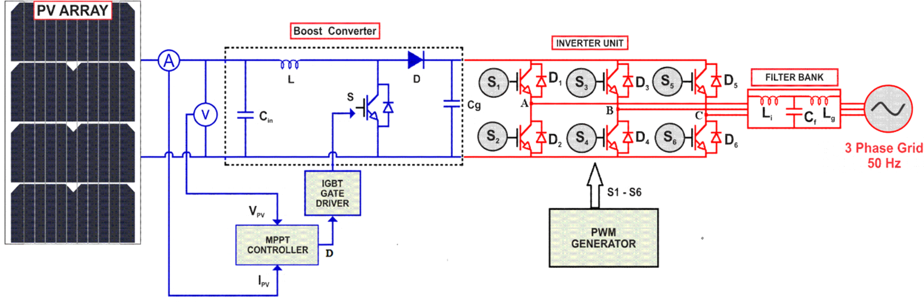
Schematic of the proposed PV structure.
Current and voltage sensors detect the outcome of PV to estimate the PV power since MPPT mainly deals with power. Each block in Fig. 1 is discussed below.
A solar cell’s equivalent structure using series and shunt resistances namely, Rs and Rsh respectively are exemplified in Fig. 2. Many solar cell elements are linked in series and parallel manner to accomplish the requisite voltage level and power rating of a PV panel. From Fig. 2, it is witnessed that, ‘I’ is the terminal current formed by Light engendered current (IL), saturation current (Io), and current in shunt resistance. The terminal current parameter is enunciated by Equation (1).
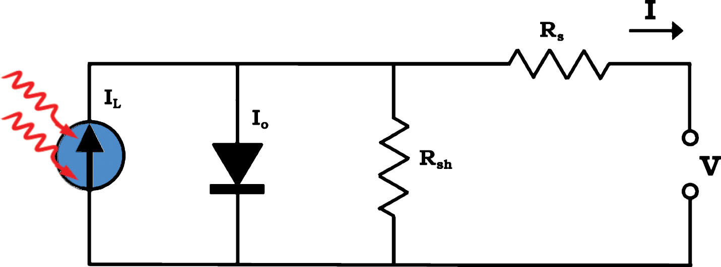
Equivalent structure of a solar cell.
Where V is the terminal voltage, kT (V) is thermal voltage, n is ideality factor and q symbolizes electron’s charge (1.6×10⁻¹⁹C) [26]. In this article, 340 W polycrystalline PV module comprising of 72 cells from Vikram solar limited is considered for the analysis [27]. Twelve such PV modules are tied to frame a PV array for grid assimilated PV network to supply 4080 W (12*340 W). All these panels are united with two strings in Total Cross Tie (TCT) topology.
Specifications of a typical panel as provided in [27] are detailed in Table 1.
Specifications of a typical PV Panel
A DC-DC boost is a voltage augmenting converter, which amplifies the magnitude of output voltage value compared to input [28]. It entails four devices which include an inductor (L), an electronic switch (S), a diode (D), and an output capacitor (Cg), as elucidated in Fig. 1. Its output voltage quantity is decided by the switching time instant of the electronic switch. The duty ratio of this switch controls the output voltage magnitude. Converter’s parameters are designed as in [29] and registered in Table 2.
Parameters of boost converter
Parameters of boost converter
In this analysis, the boost converter is fed through a PV panel. To sustain the output voltage at a constant value for meeting the load or grid, the converter’s duty ratio is tuned under drift in voltage. To procure the utmost PV power, HPO-PO MPPT is suggested in this paper, which controls the duty ratio of boost converter, to effectually track MPP while the irradiance is both at steady-state and dynamic. The losses occurring in each component of the converter significantly affect its efficiency [30]. Power losses in boost converter depend on so many factors like Conduction loss of IGBT, Turn on and Turn off losses of IGBT, Gate charge or input capacitance loss, Output capacitance loss, Diode loss, and Inductor losses which are given by Equations (2)–(7) respectively.
Where Ic and Ron represent collector current and internal resistance of IGBT, trise is the rise time, tfall denote fall time, IRMS denotes RMS current of the IGBT, VCE implies the collector to emitter voltage of the IGBT, Fsw represents switching frequency, Qgtotal indicate the total gate charge, VGE denotes applied gate to emitter voltage, Coes is the output capacitance of the IGBT, IRMSDIODE is the RMS current through the diode, while VF is the forward voltage of the diode, IRMS _ INDUCTOR indicate RMS current of the inductor and RDC signifies internal resistance of inductor in Boost converter.
Substituting these values from the datasheet of IGBT [31] and Table 2 for a maximum power of the system, these values are assessed to be 0.25 W, 0.7647 W, 0.0193 W, 0.0688 W, 4.9 W, and 4.9 W respectively. Hence the power losses in IGBT are calculated by summing the values obtained for the Equations (2)–(5), and it is assessed to be 1.1028 W. The power loss in the boost converter is found by adding all the values obtained for Equations (2)–(7), which is evaluated to be 10.9028 W. Efficiency can be assessed using Equation (8), stated as
Therefore the efficiency of the converter is found to be 99.73%.
The inverter topology employs power switching devices which can be SCRs, MOSFETs, and IGBTs. Out of these three electronic switches, the necessity of a commutation circuit for SCRs limits its application in this analysis. Whereas, IGBTs and MOSFETs are self-commuting devices. IGBTs are more suited for medium and high-power applications whereas MOSFETs are suitable for low-power applications [32]. Moreover, the study is focused on grid-connected PV systems, which will be practical in medium to high power range. Hence, an IGBT inverter is preferred in this article.
Three phase IGBT inverter consisting of six switches (S1-S6) is connected after boost converter for DC-AC conversion. A pulse width modulation generator is employed to administer the inverter switching. In order to convert non-sinusoidal voltage profile of inverter into a pure sine wave, the LCL filter is incorporated in sequence with an inverter. The regulated sinusoidal output is exported to grid to meet the load. Specifications of inverter and filter, employed in this study are calculated as in [24] and are enumerated in Table 3.
Specifications of inverter and filter
Specifications of inverter and filter
The loss in the inverter is given as follows:
From section 2.2, loss in IGBT (PIgbt) is found to be 1.1028 W for the maximum power of system. Hence the power loss in the inverter is found to be 6.6168 W. As a result, the efficiency of the inverter is evaluated to be 99.84%. Due to effective tracking of the proposed hybrid MPPT algorithm which in turn acts as input of the inverter, and due to sinusoidal pulse width modulation technique employed in VSI, the inverter losses have a very small value of 6.6168 W. Since the losses during DC to AC conversion is an essential factor to be considered in the PV implementation, immense care is taken during the PWM stage. As a result, the efficiency of the inverter has reached a high value.
The losses in LCL filter depend on inductor and capacitor losses [24]. The capacitance losses further depend on grid frequency power loss and switching frequency power loss which are given by equations (10) and (11) respectively.
Where x in Equation (11) is given by
Where uc and ui indicate grid and inverter voltages respectively, ω50 and ω SW signify angular grid frequency and angular switching frequency respectively, y indicates coefficient, Cd, and Rd represent filter capacitance and resistance values respectively. Hence substituting the respective values, the calculated values are Pd (50) = 0.017 W and Pd (sw) = 67.989 W. Inductive copper loss is given by PL = I2 R which is found to be 6.07 W. Hence the total filter loss is evaluated to be 74.076 W, and the filter efficiency is assessed to be 98.18%.
The intention of MPPT structure of extracting an enormous sun power and supplying it to load is realized by perfectly evaluating the duty cycle of converter accompanied with it [10]. MPPT regulates the converter’s operational point depending on MPP. Perturb and observation, incremental conductance, and hill climbing are conventional methods suitable for uniform and gradually altering irradiance. In this analysis, various MPPT approaches are explored to offer exalted performance in rapid varying irradiance.
P&O MPPT process
P&O technique is a simple and broadly utilized MPPT tactic in PV set-up [33]. The process intends to seek the MPP in P-V curve of a solar array. This is stated to be a modest technique since it deals solitarily with changes in power and voltage. The PV system’s current and voltage are recorded to estimate power of PV array. If there occurs a shoot-up in both power and voltage amongst two successive instants, it identifies that the present operating point is lying in the left side location of actual MPP. Hence, the duty ratio is incremented by a small value ΔD, to alter the operational point to MPP. Similarly, a fall in voltage for decrease in power also signifies the identical condition of occurrence of operational point in the left side of actual MPP. Hence duty ratio is increased for this case also.
But, an inversely proportional relationship between voltage and power for two successive instants illustrates that the operational point is currently lying to the right side of actual MPP. Hence the duty ratio is decremented by a slight value ΔD, it relocates the operational point towards left of a current position to capture the MPP.
ABC optimization based MPPT
Several research personalities have practiced ABC procedure to control MPP in PV structures. A relative investigation of ABC and P&O based MPPT for PV set-up with DC load application, to confirm the improved attributes of ABC routine under dynamic irradiance is reported in [34]. In [35], an analysis of ABC approach as MPPT with various configurations of PV array under dynamic irradiance is carried out. Every bee colony has tri agents namely scout, onlooker, and employed bees. The employed category bees fly out for looking through food components and transfer info to onlooker class bees holding up into the hive through waggle dance media. Employed bees whose food particles are relinquished, turn out to be scouts and again begin observing for food. The flowchart pertaining to ABC procedure is portrayed in Fig. 3. Phases intricated in this process are elucidated as follows.
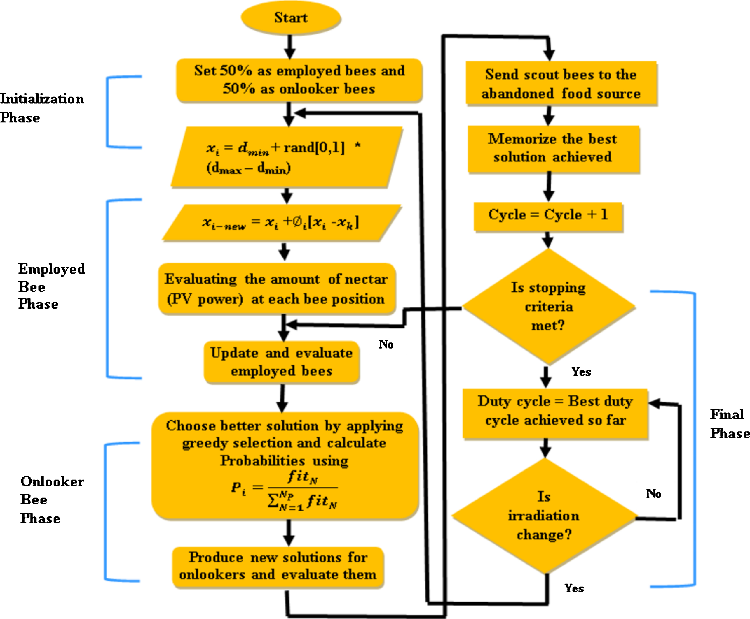
Flowchart of ABC approach.
Let colony size be initialized with S, in which 50% of it signifies employed class bees (NP). The remaining 50% denotes onlooker category bees. Former class bees are scattered entirely at various food sites employing the equation (13).
Where, i = 1, 2, ... ... NP . The variables dmin and dmax epitomize the lowest and greatest values of duty cycle (D) of the boost converter. These dmin and dmax values are chosen as 0.66 and 0.82 respectively, as listed in Table 2.
Finding the fresh food sites:
The ensuing step is to discover the food spot, with abundant nectar content (MPP) in the search area. This step is adopted by following two phases:
Newly location of every employed category of bee in the neighborhood is updated with the Equation (14).
Where k = (1, 2, ... ..Np). Its value is arbitrarily chosen and it essentially is disparate from i. The variable Ø i is randomly selected between [–1, 1].
Employed class bees deliver the data about the quantity of nectar (PV power) avail at numerous food site locations (duty ratio) to onlooker category bees through waggle dance movements. Through the acquisitive search procedure, the onlooker class bees pick the elite food site and continue to reach that best food location. While effecting the acquisitive search procedure, they remember only the extreme food site position in its memory. After the complete exploitation of food particles of an employed bee, it gets transformed to scout and flies out to discover a fresh locality. By relating the probability factor of several food locations, the best food spot with maximum nectar content is assessed. Probability is appraised by Equation (15).
Where fiti corresponds to the fitness factor of ith location and it is specified by Equation (16).
To track ultimate power, probability stated in Equation (15) is enunciated as
The overall process gets stopped and fixes the prime duty cycle, either by attaining extreme cycle number (ECN) or by having nil enhancement of PV power output, even if ECN has not attained. Thereafter, converter functions at the accomplished optimal ‘D’. This dissimilitude in irradiance is taken care of by the succeeding inequality condition given by Equation (18).
The MPP search will be performed again if the above stated criterion is gratified. The Parameters of ABC MPPT used in this investigation are chosen from [22] and they are listed in Table 4.
Parameters of ABC MPPT
The HPO method relies on psychological and mental situations of a striving person [36]. An ambitious person always plans his actions to meet his goal. A victory achieved by such a person will always be expended as a cheering process to boost his confidence level. Even from the worst situation, they learn from it and apply that knowledge in overcoming the hurdles in their path. Hence, they always develop a positive psychological spirit in all their situations [37, 38]. The cause for this positive energy relies on four factors: excitement, self-motivation, inspiration, and lesson. The flow chart of HPO procedure is revealed in Fig. 4. After computing all four factors, the energy level is verified. The bravery or confidence level of a dejected person will be too low. Hence, the mentor usually motivates and encourages such a depressed person, to escalate his/her confidence level, and thereby initiates the person in achieving his/her goal. Whereas the courage or confidence level of an over-excited person will be above the necessary level, and hence the mentor controls it by suppressing action, to facilitate in reaching his/her ambition. This attitude for arithmetical problem solutions is executed in the subsequent way to seize the PV array’s MPP.

Flowchart of HPO.
Stage 1: Creating preliminary solutions
The early result of duty cycle (D) is produced arbitrarily in the finest range as given by the Equation (19). The finest conceivable choice is (0.66, 0.82) as per converter design stated in Table 2.
Where
Stage 2 : Finding result (evaluating fitness function)
The result for each searching representative is earned by functioning the converter at that equivalent duty cycle (
Stage 3 : Apprising the victory of individual
Up to the present iteration, the accomplishment of each searching agent, namely the achieved maximum power (
Where
Stage 4 : Assigning rank concerning performance
•Position P
i
is arranged in descending order since the aim of this analysis is to enhance the PV power. Considering the Equation (22),
•Depending on power value, alphabetical names are allocated and their respective positions (rank) of all searching representatives are recorded as given in Equation (23).
The name of the top performer is fixed as A, the next one as B, and then as C, etc.
Stage 5 : Assessing the excitement factor (μ)
This factor produces populace, and offers a primary movement in a track, directing towards GMPP. It is enunciated as stated by Equation (24).
In Equation (24), Ω denotes the eagerness factor (
Stage 6: Assessment of self-motivation factor ( S)
This is a self-inspiring procedure. It improves local manipulation capability, which shoots up the convergence rate. It is expressed as in Equation (25).
In Equation (25), Ψ embodies the spirit factor and is given by (Ψ = 2 × ω).
Stage 7 : Assessment of inspiration factor ( N)
It is an impetus factor instigated by the impact of some efficacious performer. It enriches the universal search capability that can successfully hinder the forfeiture of populace diversity. ‘N’ is expressed as in Equation (26).
•‘N’ for performer B to performer J
•A (the first rank person) is the universally best person, therefore ‘N’ for A is given by
Where
Among these categories, one type is selected based on dissimilitude in maximum power (€), where € U and € L are upper and lower bounds of variance. Three possible
•Minimum
•Medium
•Maximum influence factor (when € L> €) is stated as
In the procedure of HPO, merely ω is the key factor, whose rate governs the deed of entrie system. Generally, the boundary of ω is [0.1, 1].
Stage 8 : Assessment of Lesson factor ( L)
This stage is a procedure for learning from the setbacks of others and oneself. It evades deceiving into local minima and hence eliminates saturation at local maximum point issue. It is given as
•‘L’ for performer A to performer I
•J (the last rank person) is the universally poorest performer. Therefore, ‘L’ for J is
Where
•Minimum
•Medium
•Maximum
In the above expressions, Φ symbolizes fear factor, and it’s represented by (Φ = 0.1ω).
Stage 9 : Updating human psychological approach
The ‘D’ is revised with the help of (19) –(35), and the entire revised ‘D’ is carried to the succeeding execution, in which the performance over enhancement is examined.
Where λ1 and λ2 are arbitrary numbers amid 0 and 1.
Stage 10 : Checking for over-excitement (OE) and depression (DP)
•OE: It verifies the maximum boundary. It is expressed as
Then,
•DP: It verifies the minimum boundary. It is stated as
Then,
Stage 11 : Passing of updated variables
Then the process is repeated right from the second step until the solution is not fulfilling the stopping criteria. Parameters of the HPO procedure are computed for the analyzed system, and they are listed in Table 5.
Parameters of HPO MPPT
In Table 5, ηLB and ηUB represent the converter’s duty ratio limits, whose values are obtained from Table 2. Pmax and Pmin signify the boundaries of power produced by the PV array, for the considered irradiance limits of 1000 W/m2 and 500 W/m2 respectively. ω is assumed 0.98 after numerous analyses.
Initialization of all constants is done at the primitive stage of flowchart. Also, ten initial ‘D’ values are created in the range of [Dmin, Dmax]. Just by utilizing this ’ D’ to estimate the PV power, Pmax and Pmin are chosen. These Pmax and Pmin parameters are utilized for determining the dynamic condition. These constraints act as margins of the searching zone. In the primary phase, these margins will be lying at the topmost and bottommost regions of the searching range. Also, the dissimilitude between Pmax and Pmin is enormous. But, as the procedure begins to converge in the direction of GMPP, its searching zone begins to diminish. Consequently, the gap amid Pmax and Pmin is also abridged after each iteration. This gap is very thin in stable state form. Yet, if climatic pattern variation happens during the execution of the procedure, then the ‘D’ of this instant produces few unpredicted power which is beyond Pmax and Pmin. It designates the active or dynamic pattern variation. At this instant, the values of Pmax and Pmin are abridged using steady-state error constant (ɛ). In the early period, the above mentioned error constant will be maximum. However, as the PV power variation satisfies the error state, it outcomes in the reduction of ɛ, and also in reduction of the gap among Pmax and Pmin as well.
It is a consistent procedure, and hence the wavering in constant irradiance is insignificant. Apart from the starting state, a fresh group of ‘D’ is produced in each iteration with the aid of HPO, satiating all conditions. HPO initially adopts the rank of entire ‘D’ based on the equivalent PV power utilizing (10) –(12). Thereafter, it estimates four factors with the help of (13) –(24). The above four aspects are applied in (25), by which fresh and revised ‘D’ is produced for the subsequent iteration. The procedure is repetitive in each iteration, and similar to a chain reaction. All these revised values of ‘D’ are almost equivalent to the optimal ‘D’, pertaining to MPP. Therefore, this HPO algorithm makes use of four human psychological factors to reach the optimum duty ratio of the boost converter. Activation of the algorithm in the appropriate direction during the early phase is achieved by the ‘Excitement factor’. Whereas, the ‘Self-motivation factor’ improves the local exploitation ability. Besides, the ‘Inspiration factor’ enhances global exploration abilities, while the ‘Lesson factor’ eradicates the stagnation at LMPP. As a result, HPO converges rapidly at MPP and also responds quickly in dynamic situations [20].
HPO algorithm involves eleven steps and repeats it till optimum ‘D’ is achieved, which results in improved performance. Although HPO is offering improved performance, the execution time of eleven steps at constant irradiance is unnecessary, while similar performance can be obtainable by simple P&O. But, HPO is mandatory under dynamic irradiance pattern. Hence, to earn the benefits of both HPO and P&O techniques, a novel Hybrid HPO-PO MPPT procedure is suggested in this paper. At the time of variable irradiance, activation of HPO offers enhancement in power tracks. While under constant irradiance, activation of P&O reduces execution time. Structural representation of novel hybrid HPO-PO algorithm is bestowed in Fig. 5.
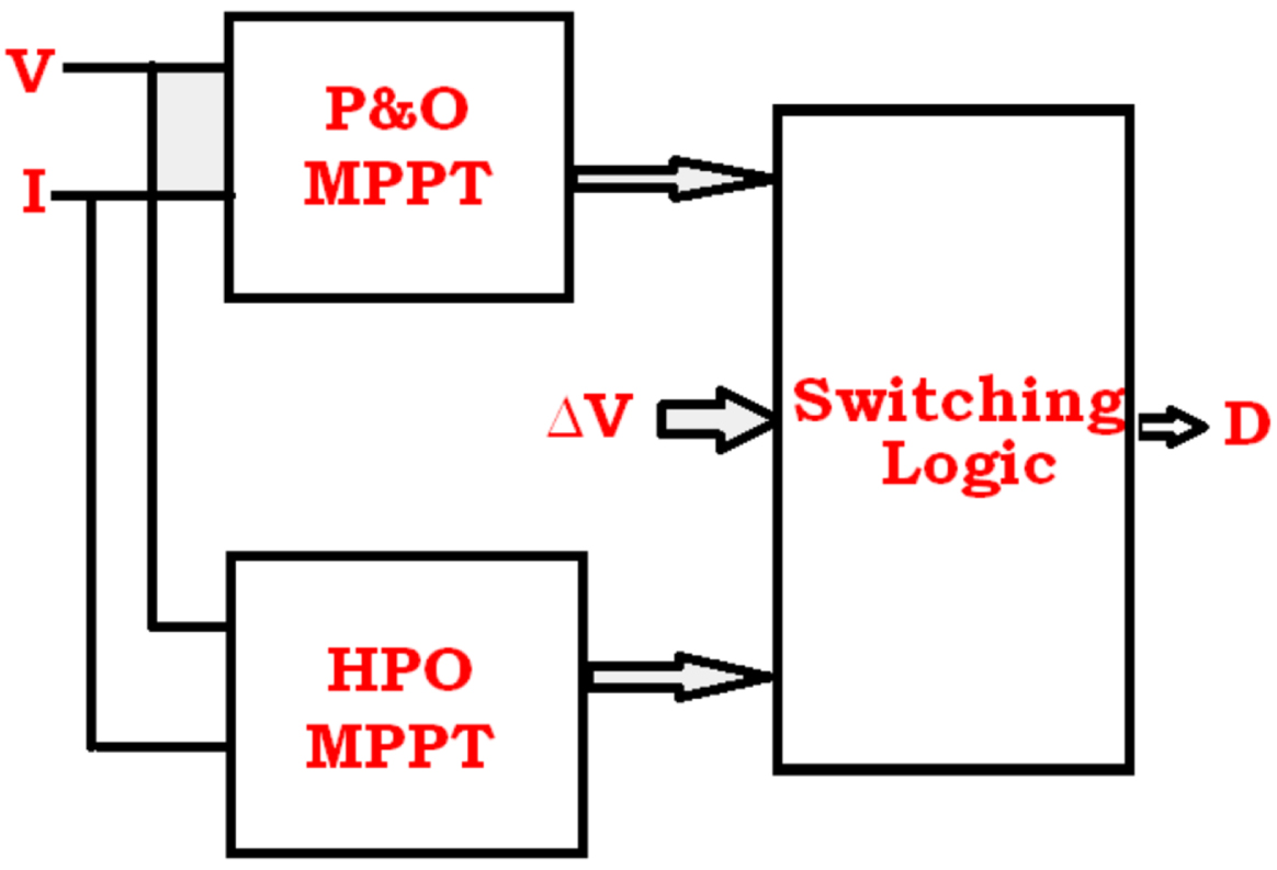
Structural representation of novel hybrid HPO-PO.
PV voltage (V), PV current (I), and change in PV voltage (ΔV) are fed as inputs to the projected hybrid HPO-PO algorithm as shown in Fig. 5, to produce ‘D’ for reaping utmost PV power. When ΔV is lesser than the threshold value, P&O MPPT is selected by the switching logic to provide a duty ratio. Instead, if ΔV is greater than the threshold value, then HPO MPPT is activated by the switching logic to produce duty ratio. Hence under variable irradiance, activation of HPO offers enhancement in power tracking, while under constant irradiance P&O reduces execution time.
In this paper, rapid and random inconsistent irradiance is considered for effectual analysis of an envisioned system. Performance of PV structure under inconsistent irradiance in the attributes of PV voltage, current, and PV power is revealed in Fig. 6. It demonstrates that PV voltage, current, and power are varying about change in irradiance between 500 W/m2 to 1000 W/m2. PV voltage varies from 122 V to 230 V, and power is produced in the range of 1100 W to 4080 W. The contour of DC link voltage under rapid and random inconsistent irradiance using various MPPT tactics such as P&O, ABC, HPO, and Hybrid HPO-PO are furnished in Figs. 7 to 10 respectively.
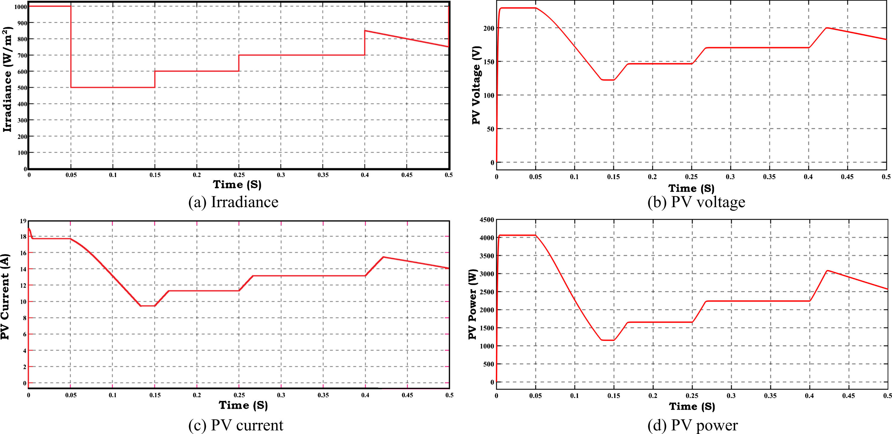
Performance of PV structure under inconsistent irradiance.
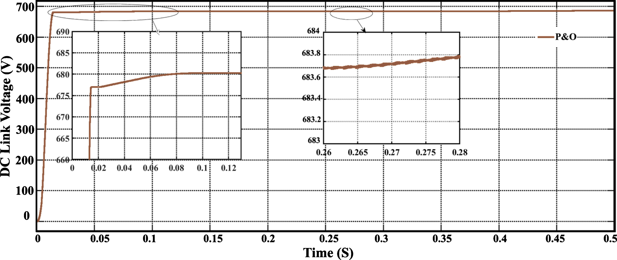
Regulated DC link voltage using P&O MPPT.
From Fig. 7, it is perceived that P&O MPPT controlled DC voltage rises quickly but swings from 677 V to 685 V irrespective of PV voltage. From Fig. 8, it is vivid that ABC takes more time for voltage settling. After settling in 678 V, it is maintained as constant for any modification in input. Figure 9 illustrates the improved demeanor of the HPO MPPT algorithm, by which voltage settles fast without any oscillations under rapid and random variation in the input voltage. Voltage settles at 679 V. From Fig. 10, it is ascertained that in hybrid HPO-PO MPPT, voltage settles swiftly at 680.5 V. Compared to all other controllers it yields oscillation free voltage with minimum steady state error. Comparative enactment of DC-link voltage using various MPPT approach is depicted in Fig. 11.

Regulated DC link voltage using ABC MPPT.

Regulated DC link voltage using HPO MPPT.

Regulated DC link voltage using HPO-PO MPPT.
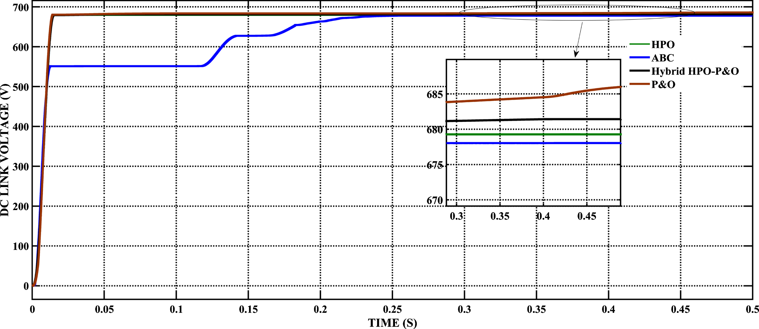
Comparative enactment of DC-link voltage using various MPPT approaches.
From Fig. 11 it is evident that the ABC process takes more settling time than HPO algorithm. The voltage yielded by P&O MPPT controlled assembly is not maintained as constant. It varies regardless of input voltage. HPO algorithm offers upgraded functioning than P&O and ABC. A slight drop in DC voltage by the HPO algorithm is compensated by the proposed hybrid HPO-PO algorithm. Hence it is suggested for grid assimilated power system analysis. The demeanor of grid voltage and current for variable load using Hybrid HPO-PO process is exemplified in Figs. 12 and 13.
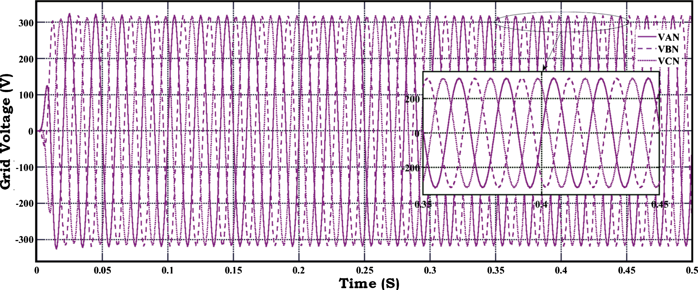
Grid voltage using HPO-PO method.
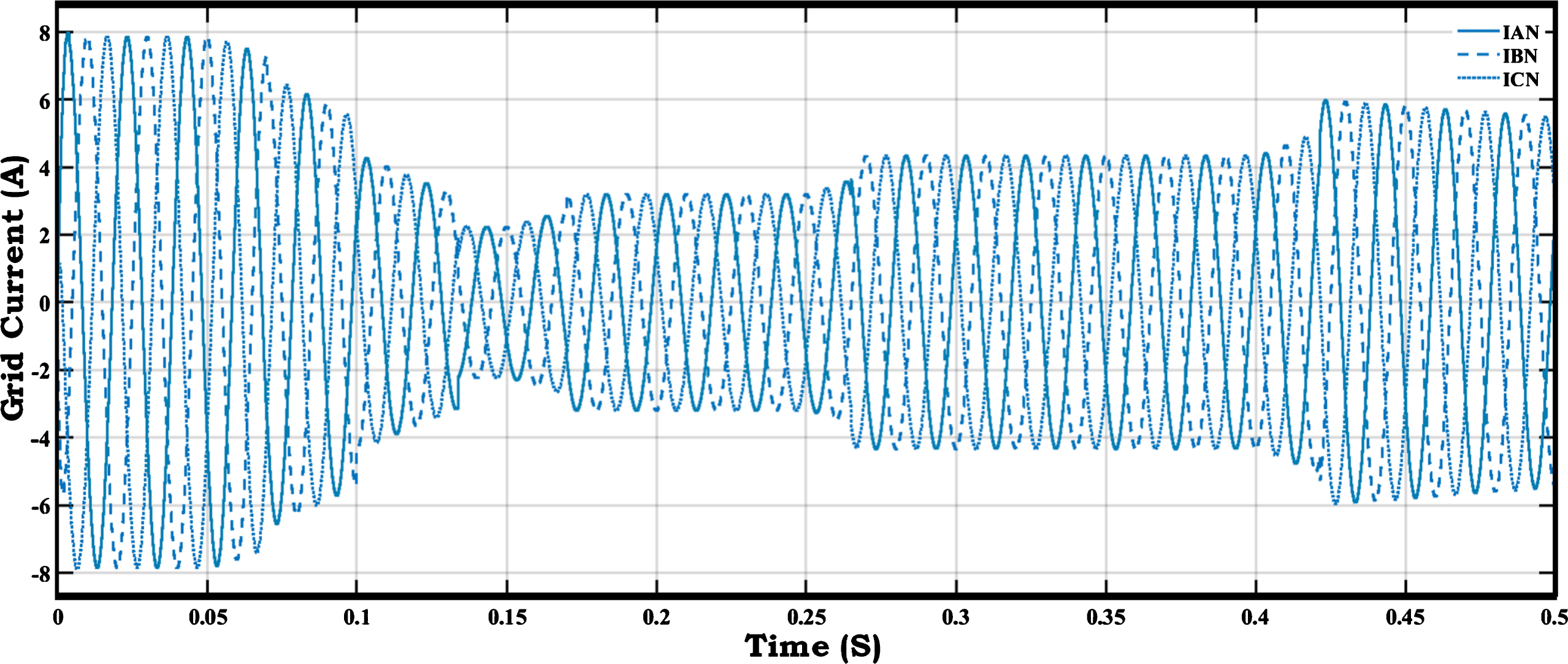
Grid current using HPO-PO method.
Figures 12 and 13 reveal that regulated and pure sine waves of phase voltages with a peak value of 338 V (Vm = 338 V), and hence line voltages of 415 V are exported to the grid, resulting in a good current profile. Total Harmonic Distortion (THD) of grid voltage and current are portrayed in Figs. 14 and 15.
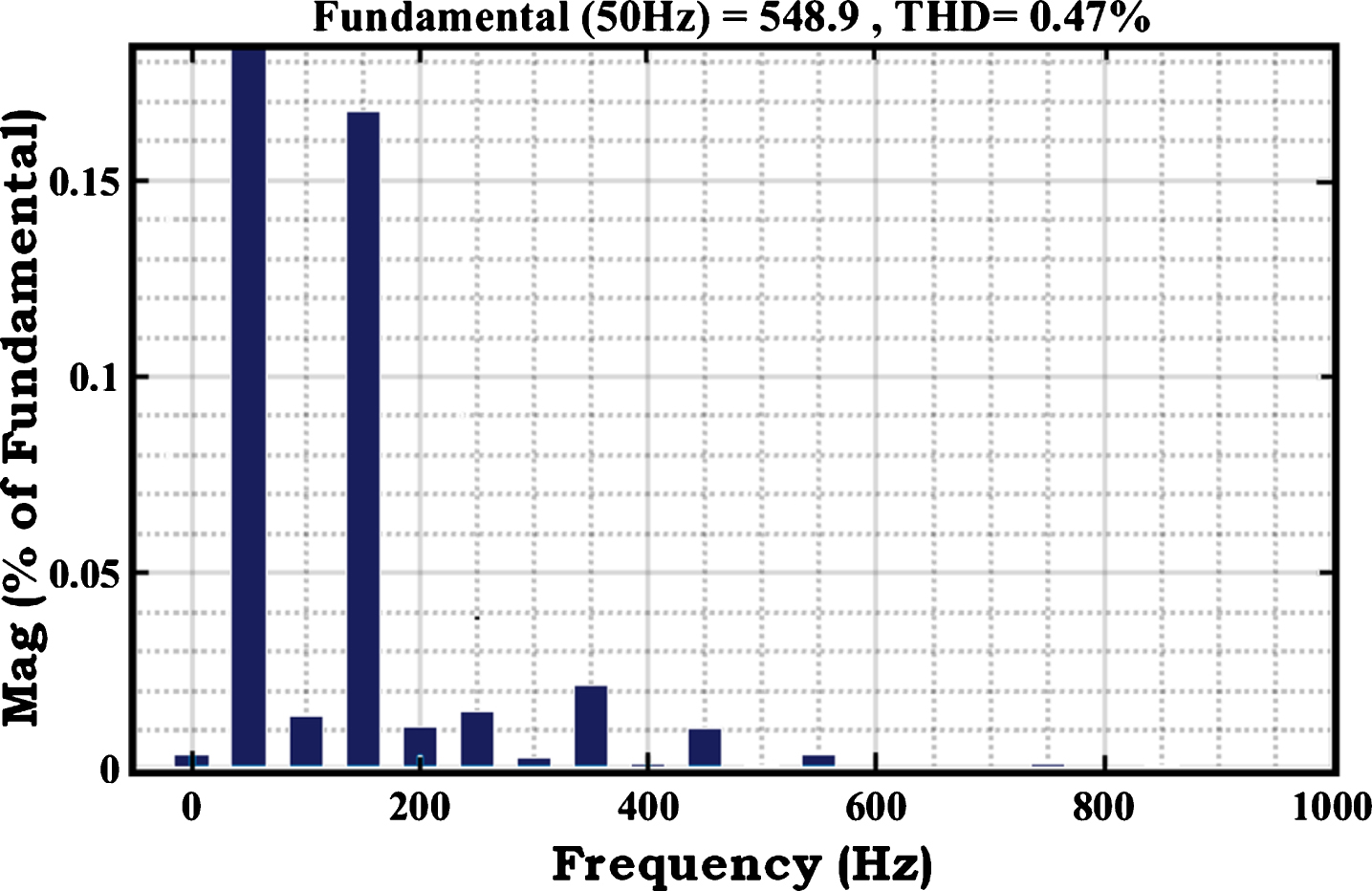
THD of grid voltage.

THD of grid current.
From the above two THD figures, it is perceived that both have an identical value of 0.47%, and comply with IEEE standards. The profile of grid power pursued by hybrid HPO-PO MPPT based PV power structure is furnished in Fig. 16.
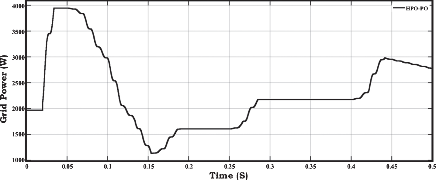
Power tracked using hybrid HPO-PO MPPT.
The extremum power tracked by the introduced hybrid HPO-PO MPPT is 3945 W when the maximum PV power is 4080 W, which results in 97% efficiency. In the case of low irradiance, PV delivers 1155 W, which is effectively tracked by the evoked system as 1130 W and offers 97.8% efficiency. The tracking efficiency of various MPPT routines is recorded in Table 6.
From Table 6, it is apparent that the tracking time of P&O is moderate, but voltage quality and efficiency are poor for rapid/random irradiance. ABC offers improved voltage quality and efficiency than P&O, while delay in tracking time minimizes its performance. HPO offers better characteristics in all aspects with minimum steady-state error in voltage than both P&O and ABC algorithms. The recommended Hybrid HPO-PO technique has enriched behavior with lowest steady-state error and highest efficiency, accompanied by better voltage quality than the other techniques studied. It offers regulated and oscillation-free dc-link voltage within 0.014 s. It has the utmost tracking efficiency of 97.72% with lowest steady-state error of 0.07%. Simulation analysis substantiates that, the envisioned system harvests maximum PV power, and offers quality power to the grid.
In India, a grid-tied PV systems are integrated with 34,915.33 MW [8]. From Table 6, it is vivid that the proposed algorithm enriches the tracking efficiency by 2.27%, 0.52%, and 0.09% when compared to P&O, ABC, and HPO methodologies respectively. Hence, an efficiency enhancement in grid-tied PV system provides an opportunity for the client to sell the excess power to the grid, in addition to meeting the load demand in a non-polluting way. The tracking speed of the analyzed algorithms is evaluated as per [20] and a comparison of the same is provided in Table 7.
Tracking Efficiency of various MPPT routines
Computational speed analysis of various MPPT routines
Table 7 reveals that the tracking speed of both HPO and the hybrid HPO-PO algorithms are very high and equal since their tracking times are minimum. Despite an increase in their computational burden, their performances are not altered by their preliminary values, and they have a low reliance on the algorithm specified parameter. Moreover, these algorithms are capable of finding the most appropriate duty ratio corresponding to a single global peak in very few cycles of execution, with the aid of four human psychological factors [20]. The presence of multiple peaks does not affect their task of determining the optimum duty ratio. Hence these two algorithms do not exhibit any oscillations and they have very fast responses. Also, it is vivid that, the proposed hybrid MPPT has a 93.63% of fast response than ABC, which is comparatively very higher then the other methods. It signifies that ABC algorithm has the lowest tracking speed and highest tracking time than the other compared algorithms. This is because, even though its computational burden is less when compared to the suggested hybrid algorithm, ABC method takes much time to settle in case of the prevalence of multiple peaks due to usage of random values in every initialization phase. In spite of its delay in tracking, it does not produce any oscillations in its steady-state. Since the computational time of optimum duty ratio to attain global maximum power without any oscillations is more, this method has slow response than the other compared methods. Whereas Table 7 illustrates that P&O algorithm has moderate tracking speed and time than the other methods. Despite its simple procedure and less computational burden, it produces many duty cycles if there occur multiple peaks, and produces oscillations and instability response in their steady-state. Therefore its tracking time is more than the suggested hybrid algorithm, and hence its tracking speed is less than the proposed algorithm. However, even though this algorithm does not produce an optimum duty ratio corresponding to global peak, it produces many duty ratios in very less time. Hence the P&O algorithm has fast response than ABC, but with oscillations in its steady-state.
One day analysis is presented in Fig. 17, to validate the efficacy of the proposed hybridized algorithm in real-time conditions. Figure 17 (a) depicts 24 different irradiance conditions that fall within the designed boundaries of 500 W/m2 to 1000 W/m2. Since the converter which has been designed in this system operates with an input voltage ranging from 122 V to 230 V, corresponding to 500 W/m2 to 1000 W/m2 of irradiation, the deep dark condition of the designed system will be 500 W/m2. It is clear from Fig. 17 (a) that the considered irradiance conditions start from 1000 W/m2, and the deep dark condition of the designed system occurs at 1 AM and also at 11 PM of the day. From the Fig. 17 (b), it is clear that even during this dark condition, the dc-link voltage provided by the boost converter along with the suggested algorithm has reached around 680 V irrespective of its input voltage of 122 V fed from the PV array. Also, it illustrates that, as the irradiance pattern changes, the output from the PV array changes as well. However, the proposed hybrid algorithm’s ability to provide a constant and regulated dc-link voltage of around 680 V over one day with 24 different irradiance conditions, validates the algorithm’s efficiency and dynamic nature. Since the tracking time of the proposed algorithm is 0.014 s, the dc-link voltage attains its constancy within very few seconds of the start of the simulation, and hence it is not visible in the one-day simulation which has been plotted in hours.

One-day Performance analysis of the proposed hybrid MPPT algorithm.
Figure 17(c) shows that the PV power produced during the dark condition is 1100 W, and it gradually rises to 4080 W when the radiation rises to 1000 W/m2. However, the tracked power of the suggested algorithm closely follows its respective PV power for the entire duration, owing to its very small tracking time of 0.014 s. Hence, it is very highly efficient in tracking global peaks and thus provides superior and reliable performance throughout the day.
The hardware set-up for implementing the proposed hybridized algorithm along with HPO and PO is provided in Fig. 18. PV simulator serves as a PV source. The duty cycle of the boost converter’s electronic switch is controlled by the algorithmic rules of the proposed hybrid algorithm implemented in the dsPIC30F2010 Enhanced Flash Digital Signal Controller.
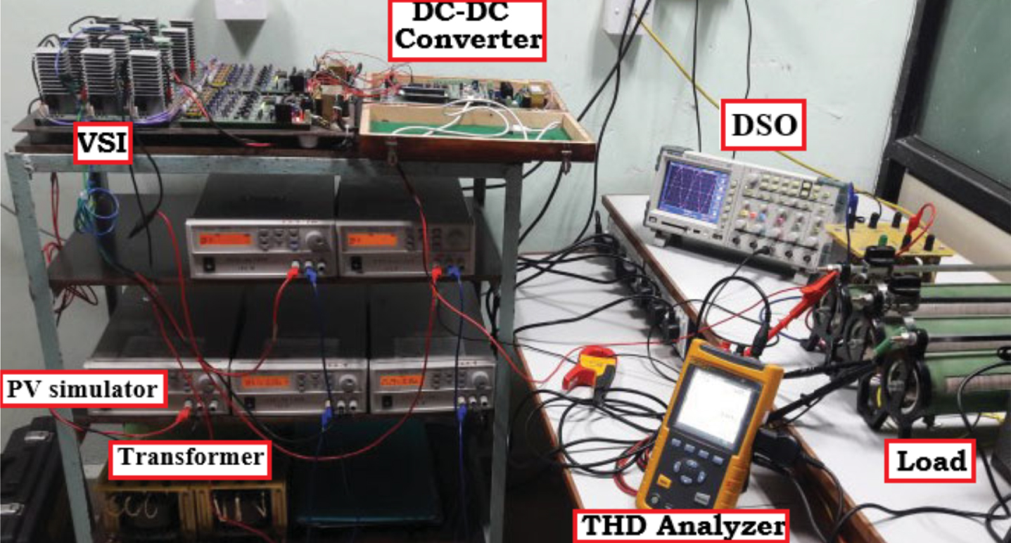
Portrait of hardware set-up.
The purpose of choosing 16-bit dsPIC30F2010 Digital Signal Controller for implementing suggested MPPT algorithm is due to its high-performance activity, which combines DSP computational capabilities with microcontroller simplicity. Hence it completes its complex computations very swiftly. It performs 30 Million Instructions Per Second (MIPS). Moreover, it is an industrial-grade controller which is suited for operating temperatures of (–40 to 125) °C [39]. It also incorporates single-cycle 17 X 17 Multiply Accumulate (MAC) operation with two 40-bit accumulators, making it ideal for math-intensive control, digital power conversion, and high-performance embedded applications. The purpose of selecting dsPIC is presented below in Table 8 with a comparison of other controllers/processors.The dsPIC receives voltage and current patterns from the simulator. The output of the boost converter is given to three phase VSI with an LCL filter, feeding a three phase non-linear RL load after filtering. Practically, a grid can be considered to be a RL load. Hence in this study, RL load is used in place of the grid. DSO and THD analyzers are employed to measure the hardware results and THD of the output waveforms. The specifications of the components used in the real time implementation are the same as that of simulated values. The qualitative output ensures the capability of the analyzed system in meeting its load in real time conditions, and the possibility of its grid connection in future.
Comparison of dsPIC30F with other processors and controllers
The PV simulator is made to simulate the solar array characteristics with voltages in the range of (122–230) V. Response of the converter activated by the proposed hybrid algorithm for 122 V input, corresponding to irradiation of 500 W/m2 is displayed in Fig. 19.
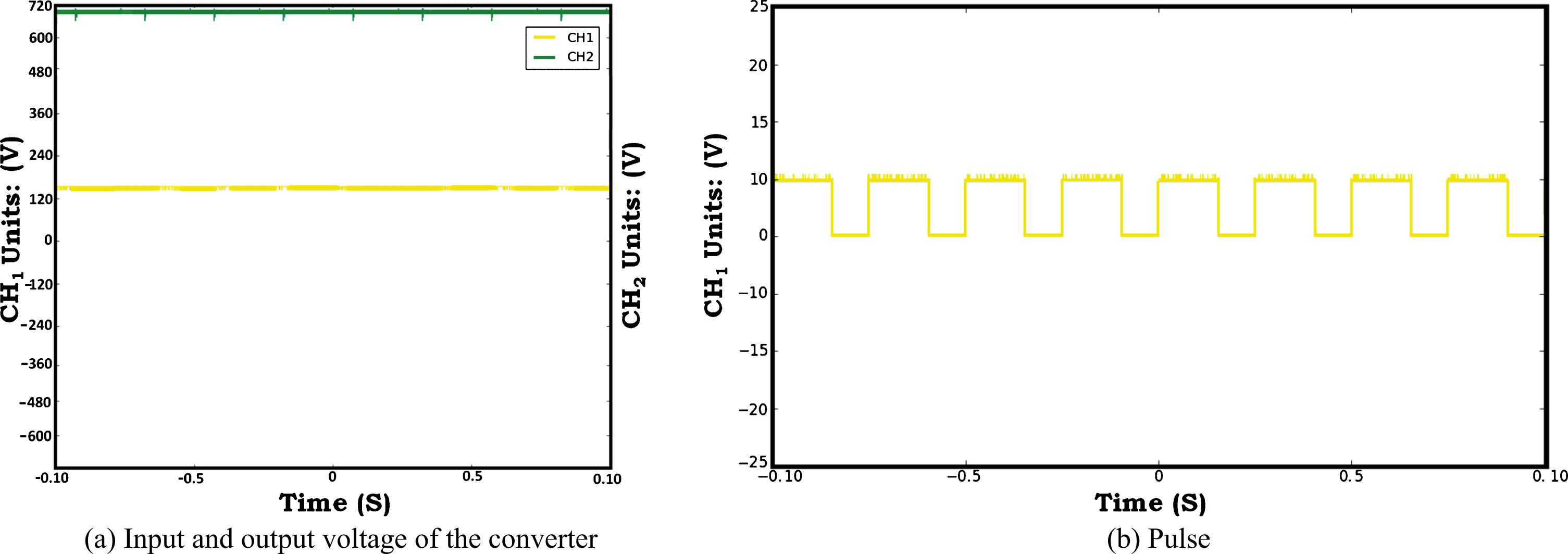
Response of converter for 122 V input.
In Fig. 19 (a), CH1 and CH 2 provide the input and output voltages of the converter respectively. A steady boosted output voltage of 680.68 V is procured from the converter output terminals with the aid of pulses generated shown in Fig. 19 (b) following the developed and implemented algorithm in dsPIC. Performances of the recommended system, with converter input voltages of 210 V and 230 V, are displayed in Figs. 20 and 21 respectively.
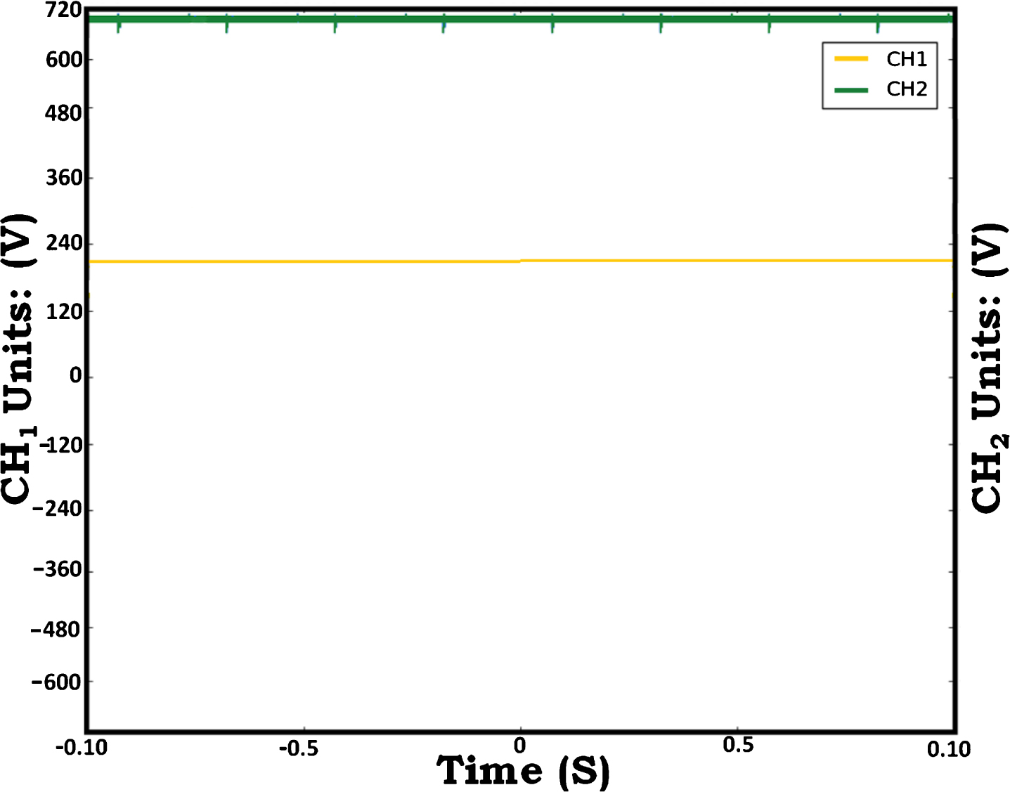
Response of novel hybrid algorithm for the input of 210V.
The HPO-PO algorithm coded in the dsPIC controls the duty ratio of the IGBT present in the converter and thus provides controlled pulse width, allowing the converter voltage to be regulated to 680.68 V regardless of input variations. Hence these two figures namely Figs. 20 and 21, elucidate the efficient operation of the implemented hybrid algorithm in tracking the maximal power under rapid input changing conditions. The experimental THD spectrum of the output voltage is displayed in Figs. 22, and 23 offers the details of various AC powers present in the system for the converter input voltage of 122 V. Figure 22 demonstrates that, in addition to a fundamental component, all odd harmonics up to 17th order, prevail in the system. Further, since the harmonics in all three phases are uniform, the output voltages in all phases are balanced. The THD spectrum, with a value of 0.6 %, ensures that these output voltages have very minor distortions and are well within the IEEE standard. This remarkable low THD is obtained due to the effective operation of the inverter and filter.
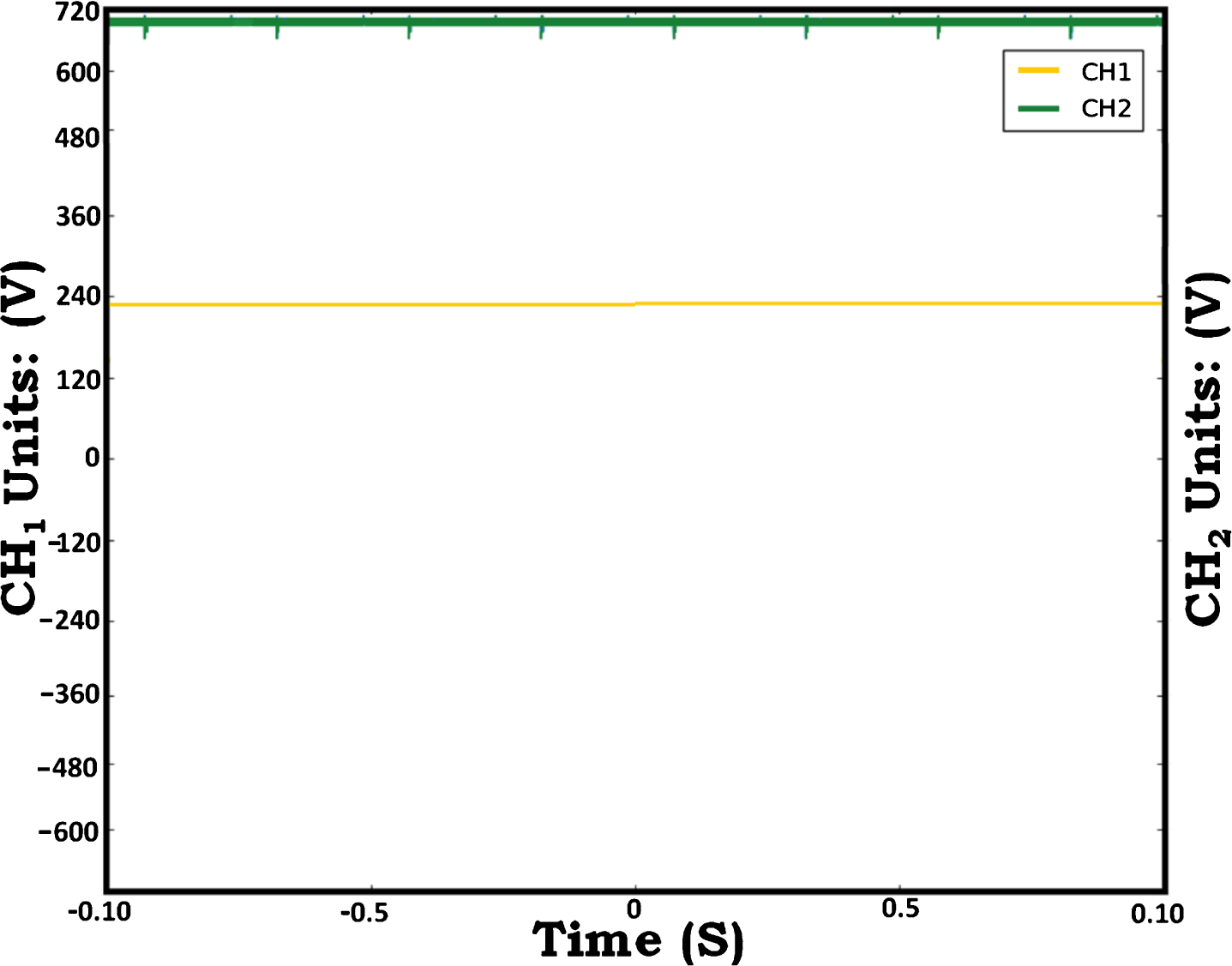
Response of novel hybrid algorithm for the input of 230V.
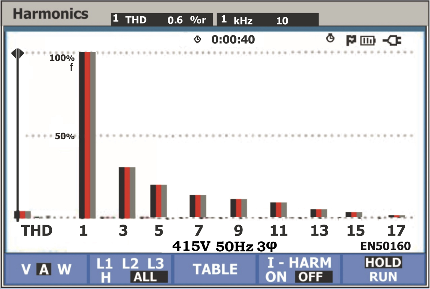
Experimental THD spectrum.
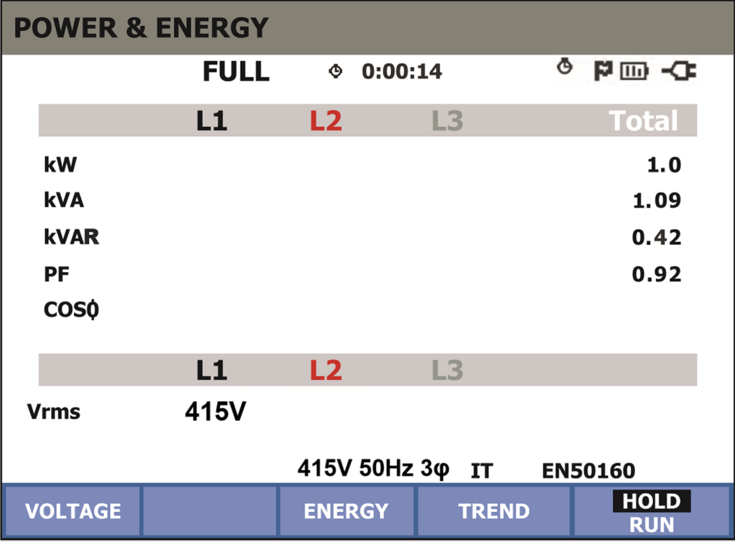
Various AC powers in the system with converter input of 122 V.
Figure 23 shows that three phase voltage waveforms at 50 Hz and 415 V, have a power factor of 0.92 due to the RL nature of the load connected. For the converter’s input voltage of 122 V, which corresponds to a 500 W/m2 irradiation, the grid has 1 kW of active power available. Since the PV power produced in this dark condition is 1100 W as observed from Fig. 6, the efficiency of the considered PV system with the suggested hybridized algorithm is assessed to be 91%. On the whole, undistorted three phase balanced voltages at rated frequency and magnitude, combined with experimental efficiency of 91% along with a very low THD of 0.6%, make the system more suitable for connecting to the grid in the future. Furthermore, due to the efficient tracking of the hybrid HPO-PO algorithm embedded in dsPIC, the implemented system has been able to achieve this remarkable efficiency of 91%.
An innovative hybridized HPO-PO algorithm is proposed in this article for obtaining the optimal duty cycle of the boost converter to harvest global maxima from a grid-connected TCT configured PV array of 4080 W. This hybrid algorithm is obtained by integrating the HPO algorithm and PO algorithm, for harvesting global peak power under steady-state and as well as dynamic conditions of the atmosphere. Enhanced behavior of the suggested MPPT algorithm is discussed with the comparative simulation analysis of other MPPT approaches like P&O, ABC, and HPO in the aspects of voltage quality, settling time, tracking efficiency, tracking speed, and steady-state accuracy. The simulated results proved that the proposed algorithm enriches the tracking efficiency by 2.27%, 0.52%, and 0.09% when compared to the P&O, ABC, and HPO methodologies respectively. It offers regulated and oscillation-free dc-link voltage within 0.014 s. It has the utmost tracking efficiency of 97.72% with lowest steady-state error magnitude of 0.07%. One day simulation analysis is also been carried out to validate the efficacy of the proposed hybridized algorithm in real-time conditions, with 24 different irradiance conditions falling within the designed boundaries of 500 W/m2 to 1000 W/m2. Then the performance of the inverter with filter is validated by its THD value. The existence of 0.47% of THD in the simulated voltage and current meeting the IEEE standard. It llustrates the quality of electrical quantities exported to the grid. Then the recommended hybridized MPPT approach is experimentally validated on a hardware set-up by using a 16-bit dsPIC30F2010 Digital Signal Controller enhancing the behavior of the grid-tied PV system. The system implemented has a 91% efficiency with a 0.6% THD, which meets the IEEE standard, ensures its superior performance in real-time compliance, and a better system for quick grid connectivity. In future, the suggested hybridized algorithm may be utilized for the performance enhancement of grid connected PV structure under partial shading conditions as well, along with some other modified form of boost converters.