



Abstract
The intelligent control strategy of electromagnetic clutch actuator is analyzed in detail in this paper. The start - stop control of the loom is realized by an electromagnetic clutch. The existing control method of electromagnetic clutch of loom is high and low pressure control strategy. The operator sets the braking advance angle according to experience, to realize the accurate braking of the spindle, but it is difficult to realize the fast and accurate control. In order to achieve good performance, it is very important to develop a fast and accurate loom braking system. Aiming at the fabric defects caused by the elongation of the warp when the loom is stopped, a method of stabilizing the excitation current of the electromagnetic clutch by using the neural adaptive PID (proportional integral differential) controller is proposed to improve the control precision of the actuator. The experimental results show that the proposed control algorithm is feasible and can effectively realize the adaptive control of the spindle braking Angle within the allowable error range.
Introduction
The start-stop control of the loom is an important part of the weaving process and the electromagnetic clutch is an indispensable part of the loom. When the loom is started, it transmits the kinetic energy of the motor to the spindle. When the loom stops, the loom quickly stops by the electromagnetic clutch. The startup of the loom does not involve accuracy issues, but when the loom stops, the error between the angle where the spindle is located and the set point should be within 10°. As shown in Fig. 1. The process flow of loom can be represented by a circle according to the rotation angle of the spindle. The loom needs to complete the corresponding action in different angle ranges. The loom stops manually or when the weft breaks, generally, it needs to stop at 310° [1]. At this angle, the heald frames are flush with each other and the warp yarns have the least tension, which can avoid fabric defects caused by the warp yarns’ elongation.
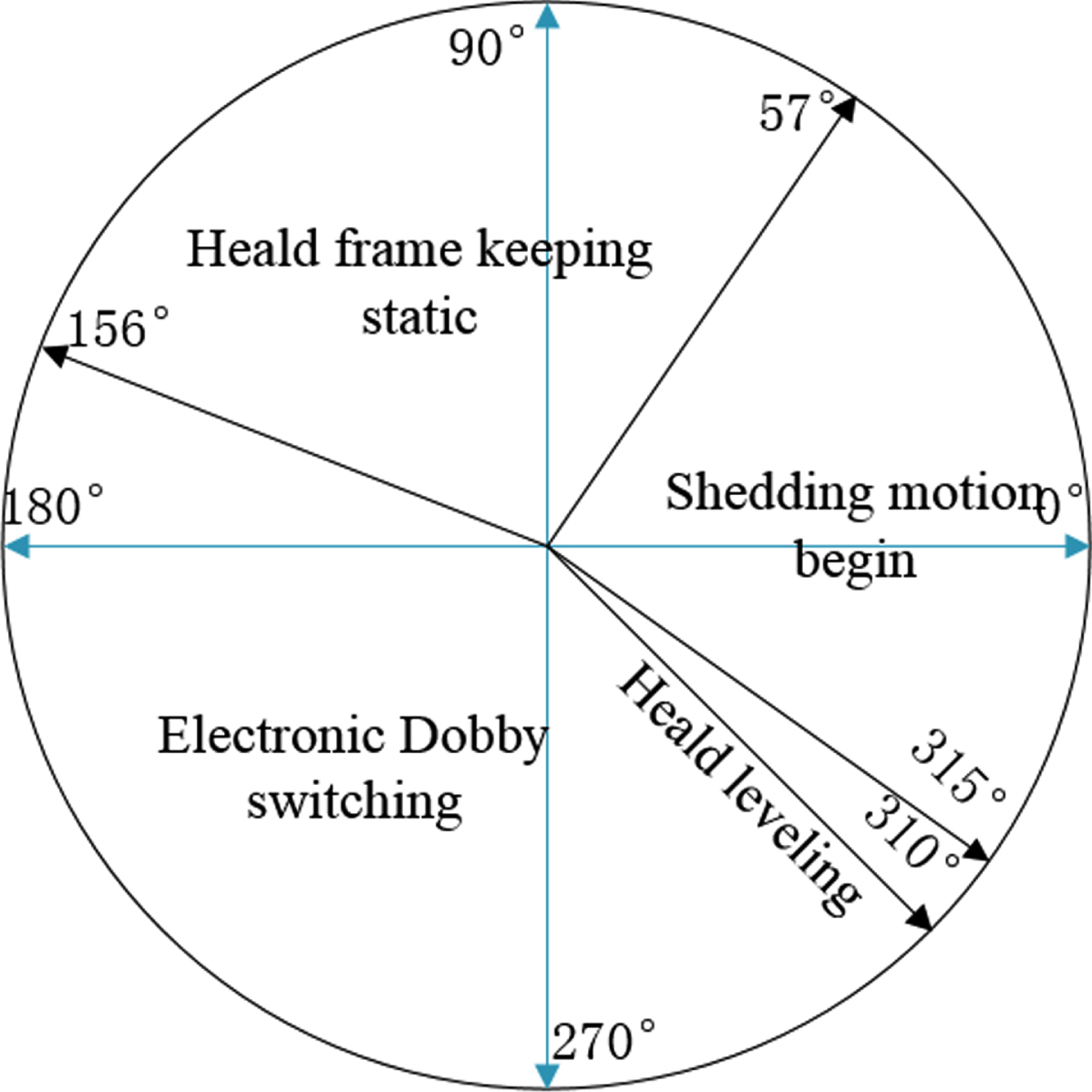
Technology circle of the loom.
The traditional braking mode of the loom is high-and-low voltage control strategy. A transformer is used to supply voltage to the electromagnetic clutch. In the initial stage of braking, a high-voltage power supply is used to rapidly increase the current of the clutch coil. After the braking process is completed, the clutch is maintained at low voltage. During the braking process of the loom, considering the inertia of the spindle and the delay of the clutch engagement, the braking process is generally started some angle in advance. This creates some problems, the presence of the transformer makes the controller of the loom cumbersome. The open-loop control of the electromagnetic clutch cannot guarantee the stability of the excitation current. The braking advance angle needs to be set by the operator based on experience, which is neither intelligent nor accurate.
The control of the loom braking process is essentially the control of the electromagnetic [2]. The controller needs to keep the clutch coil current stable and calculate the appropriate braking advance angle. In order to facilitate the integration of the brake controller in the loom controller, it should also be considered whether the control algorithm can be applied to a low-cost, small-volume microcontroller.
Zhou, X. Q [3] carried out simulation research on the beating-up mechanism, sheading mechanism, and weft insertion mechanism of the rapier loom through Pro / E, and obtained the change rule of the inertia load of the loom spindle. This is of great significance for the study of the angular error generated during the braking process of the loom. Yuan, Q. Q [4] proposed a braking control method of the loom spindlebased on PID controller. According to the detecting the angle and load of the spindle, the current of the coil was adjusted in real time, but it was not verified. The driving circuit of the electromagnetic clutch is generally Buck chopper, closed-loop control by PID controller. PID controller is not the most suitable control method of Buck chopper. With the development of nonlinear control theory and intelligent control theory, increasing control methods are used to control such nonlinear systems.
For example, intelligent adaptive control based on various intelligent algorithms [5], robust control [6], sliding mode control [7, 8] and so on. Among them, fuzzy control is an intelligent control system developed from fuzzy mathematics, which can simulate human thinking and experience, so it is suitable for controlling complex nonlinear systems [9]. Fuzzy control is often combined with other control strategies to achieve better results, such as fuzzy PID control [10], fuzzy sliding mode control [11], fuzzy neural network [12], fuzzy genetic algorithm [13], and so on. However, these common control methods are difficult to obtain good accuracy and robustness.
How to accurately control the displacement and running speed of the electromagnetic clutch in the process of moving, to control the start and stop of the loom, is the key and difficult point of the process control of the electromagnetic clutch. In addition, the start and stop of the loom need to be controlled in advance, and the current PID control cannot meet the requirements. With the development of neural network technology, neural network is suitable for self-learning, self-adaptation, and other complex control problems. It is an effective solution for multivariable systems with cross-coupling of internal parameters. Therefore, in this paper, the neuron-adaptive PID is used to stabilize the electromagnetic clutch coil current. On the basis of stable clutch coil current, the angular error of the spindle after braking under different conditions was tested. Then, based on the measured data and operating experience, a neuron-adaptive controller of braking advance angle is designed.
The rest paper is organized as follows. The second section introduces the transmission structure of the loom. The third section introduces the mathematical model of Buck chopper and electromagnetic clutch. The fourth section analyzes the factors that affect the braking accuracy of the loom spindle and designs the controller of the electromagnetic clutch and the neuron-adaptive predictive controller of the braking angle advance. The fifth section shows the experimental results. Finally, a conclusion and a reference list end the paper.
The control object of this paper is a friction electromagnetic clutch. The transmission disc is combined with the rotor of clutch and friction disc, respectively, to realize the starting and braking of the loom. Buck converter is used as the driving circuit of the electromagnetic clutch, and the switching device is IGBT. As shown in Fig. 2 [14], the combination of the rotor and the transmission disc to realize the startup of the loom. The combination of transmission disc and friction disc to realize the braking of the loom. When the loom is braked, the transmission disc is separated from the rotor first, and then the braking electromagnet B of the electromagnetic clutch is electrified, so that the transmission disc A and the friction disc is closed to realizing braking of the loom.

Structure diagram of electromagnetic clutch for loom. P1&P2: Pulley, M: Main motor, A: Transmission disc, B: Braking electromagnet, C: Starting electromagnet, D: The rotor of electromagnetic clutch.
Mathematical model of Buck chopper
The driving circuit of the electromagnetic clutch is Buck chopper, which can be integrated with the microcontroller to replace the bulky transformer. The circuit is shown in Fig. 3:
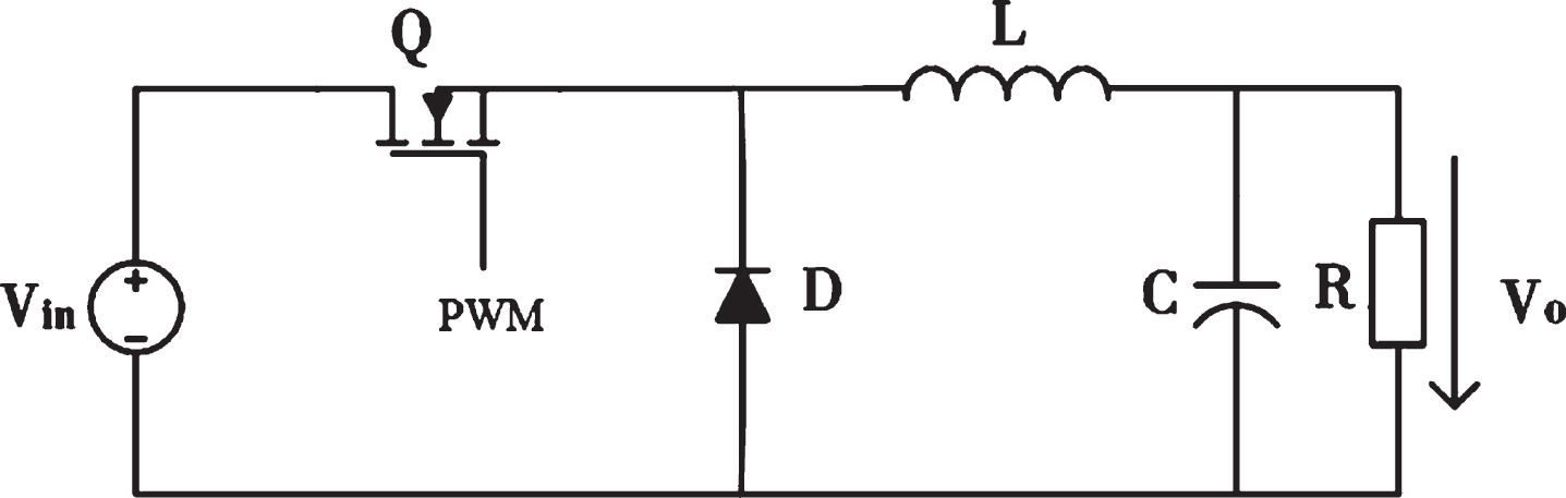
Circuit of Buck chopper.
It is assumed that the IGBT is an ideal switching device, and the coil of the electromagnetic clutch is replaced by an equivalent resistance. Take the inductor current i L and capacitor voltage u C as the state variables of the system.
When the IGBT is on, the state equation of the system is:
The input DC power is directly obtained by 220 V AC power rectification, and the voltage is
The excitation coil of the electromagnetic clutch can be equivalent to an RL circuit, Inductor has a hindering effect on the current, the increase of the current is a process of increasing from zero.
The differential equation of clutch excitation coil is:
Where C is the integral constant, From Equation (8), we can find that the excitation current changes exponentially. But when the electromagnetic clutch overcomes the external force and starts to engage, the air gap δ decreases gradually. It can be seen from Equation (6) that the excitation current i in the circuit will also gradually decrease. When the clutch is engaged, the current recovers exponentially and finally reaches a steady state.
Neuron-adaptive control of braking advance angle
The control of the excitation current of the electromagnetic clutch is only a prerequisite for the control of the braking process of the loom, and it can make the braking process of the loom as far as possible from external interference. This is important to accurate braking of the loom. In addition, the speed and inertia load of the loom’s spindle will also affect the braking accuracy, and the pick-up time of the electromagnetic clutch cannot be ignored too.
Angular error at different target angle
The spindle of the loom needs to drive the gripper band, beating-up mechanism and heald frame. Indeed, the inertia load of the spindle of the loom is related to the current angle of the spindle. According to research about the inertia load of loom spindle, it can be seen that the load of loom’s spindle changes regularly with the change of angle. Similarly, due to the different inertia load on the spindle, the braking process of the spindle at different target angles will also produce different angular errors.
As shown in the Fig. 4, we tested the angular error at different braking target angles when the spindle speed was 350r / min, and then performed curve fitting. From the data in the Fig. 4, it can be seen that the angular error changes regularly in a period. This indicates that at the same spindle speed, the braking start angle will affect the angular error of the braking process.
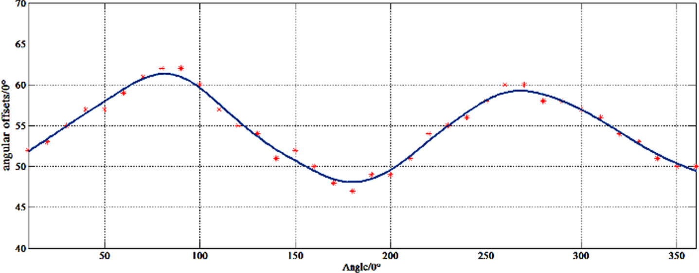
Angular error of different angles.
The spindle speed is also an important factor that affects the angular error. The greater the spindle speed, the greater the moment of inertia, the more energy is needed for braking, and the angular error increases correspondingly. As shown in the Fig. 5, setting the start angle of the braking process to 310° and testing the angular error at different spindle speed. The angular error increases with the increase of spindle speed and has an approximately quadratic relationship with the speed.
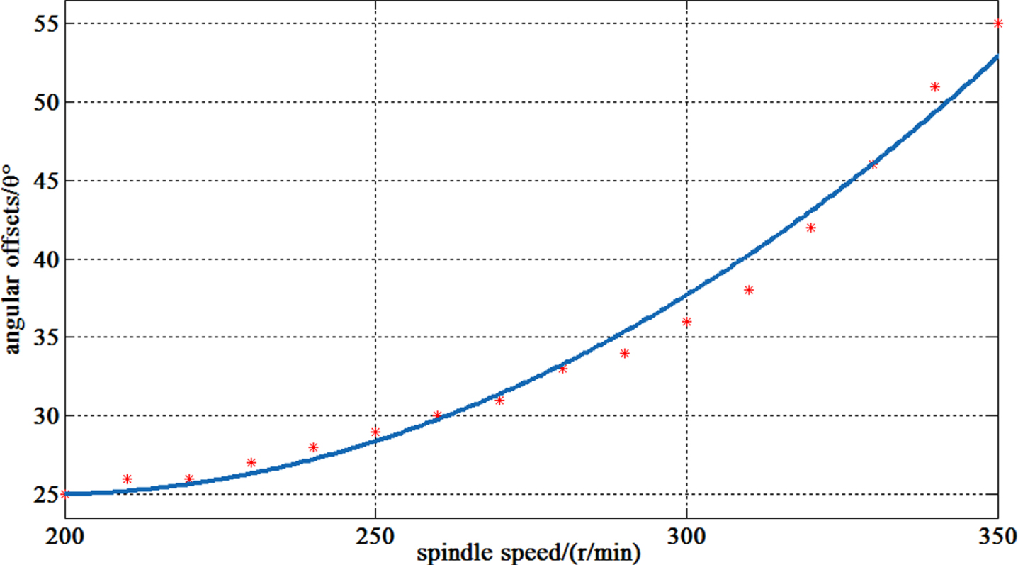
Angular error at different spindle speed.
At the beginning of the braking process, the electromagnetic clutch cannot immediately generate braking force. The rising process of the clutch coil current is shown in Fig. 6:

Rising process of clutch coil current.
Before the time t1, the current is not enough to make the clutch to engage. Between t1 and t2, the electromagnetic clutch starts to engage, and at time t3, it reaches 80% of the maximum torque. Therefore, before the time t2, the spindle only receives the effect of the clutch’s dynamic no-load torque, and the spindle speed decreases slowly. After time t2, the clutch output torque gradually increases, and the spindle speed starts to decrease rapidly until it stops. Therefore, the pick-up time of the electromagnetic clutch also affects the angular error of the spindle braking.
The electromagnetic clutch uses the electromagnetic energy to realize the transmission of the output torque and the mechanical energy ∖to stop the spindle of the loom.
Buck chopper and electromagnetic clutch are typical nonlinear systems, and PID controller can not achieve good control effect. Many intelligent algorithms have been used for on-line adjustment of PID parameters to achieve precise control of nonlinear systems [15, 16]. Clutch in the whole service life, will produce different degrees of wear and tear, prolong the use of time, effective control of the clutch travel position will change, affect the control effect. Therefore, the control strategy, in addition to using the neuron PID control algorithm, but also the adaptive function, requires effective control of the clutch stroke outside the real-time position feedback, to ensure effective control of the clutch stroke in real-time accurate position. The PID controller composed of a single neuron adaptive linear neural network is simple in structure, ADAPTS to environmental changes, and has strong robustness. Therefore, this paper uses neural adaptive PID to establish the clutch process control system to realize the precise control of clutch displacement and running speed. The control system structure is shown in Fig. 7.
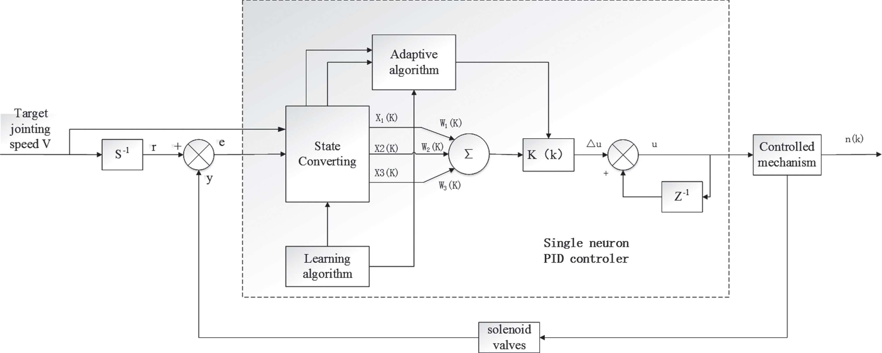
Control model based on adaptive neuron PID algorithm.
The activation function of a single neuron network is a linear function, and the output of the neuron is:
The clutch target engagement speed V is the neuron input, the neuron input is the feedforward control variable, the other two inputs are the clutch position error and its difference value. Therefore the Xi (k):
The selection of neuron proportionality coefficient K is very important. The larger K is, the better the control rapidity will be. However, the system is not stable.
The following is the flow chart of the adaptive algorithm in Fig. 8. Firstly, the implementation process and method of the self-learning program are determined. The calibration of effective clutch Angle control is the main content of self-learning program. According to the characteristics of effective angle, the whole angle range is the working stage and the constant transmission stage in the process. Therefore, the active transient displacement of engine speed is recorded in real time through the output of displacement sensor signal during the whole operation process, and the clutch control angle parameters are modified regularly and in real time through the corresponding weighted average algorithm.
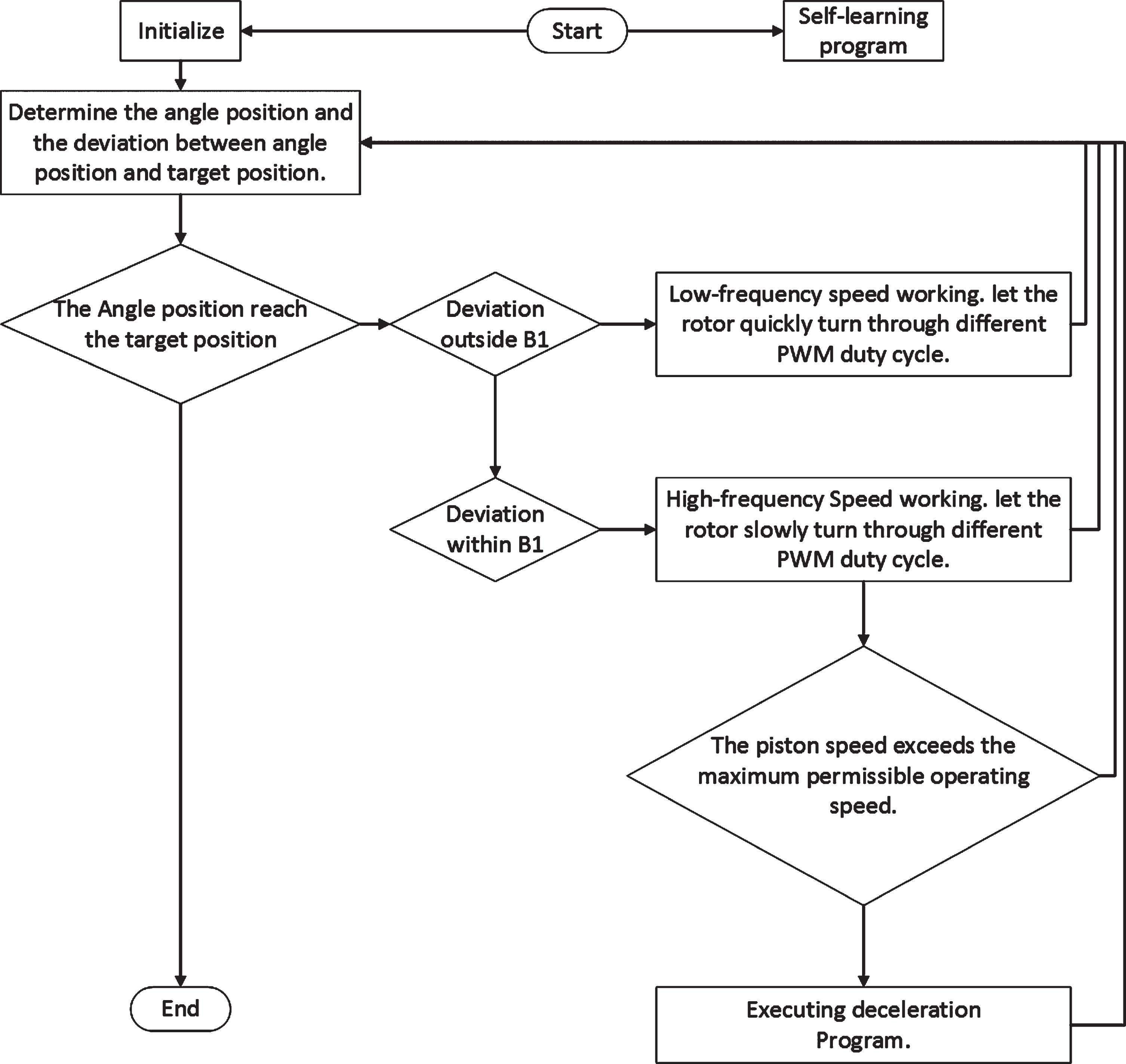
Flow chart of the adaptive algorithm.
Second, perform clutch actuator start and berth position initialization. When the motor is installed for the first time or the system is maintained regularly, the angle of the motor needs to be initially calibrated. The range of motor angle during working was recorded, and the increase of average value, average evaluation and post-correction coefficient was calculated, which could be considered as the normal working angle value of this value. When the clutch is completely disengaged, the angle value when the clutch is completely disengaged can be calculated through the disengaging angle and correction coefficient of the clutch. This method is different from the engagement method. After entering the control program, it is time to confirm the target value and angle position. Wherein, combined with the relevant characteristics of clutch diaphragm spring, an appropriate angle target position range A is set, and the deviation range B is set between the current angle position and the target position. Set the fast motion range outside the B1 range, and start the slow steady motion within the B1 range.
When the target reaches the required position of the clutch in the shortest possible time, determine the actuator angle deviation interval, the interval and fast moving area, rapid action to achieve the target in the clutch near cheer up, when entering near the target range, perform the slow movement, update in real time, adjust the duty cycle, to achieve fast and stable control effect. As the target value is approached in the final stage, more precise angle control is required to ensure that the actuator can stop at the target value. At this point, the maximum allowable working speed of the full stroke is calibrated. When the angle exceeds the preset value, the corresponding duty cycle is reduced and the speed is slowed down to the target value.
Finally, when the dynamic system controller to input data to the appropriate angle control program time-varying angle curve, it can be through the implementation of a complex non-linear system.
Simulation analysis
To verify the feasibility and performance of the control algorithm, a neuron-adaptive PID controller simulation model of the clutch coil is established in MATLAB. The obtained response curve is shown in Fig. 9 and the specific performance of the controller is shown in Table 1. According to the simulation results, the rise time, settling time, and delay time of the neuron-adaptive PID controller were 71.5%, 27.3%, and 18.8% of the PID controller, respectively. The results show that the neuron-adaptive PID controller can improve the response speed of the system and reduce the maximum overshoot and has a better control effect.
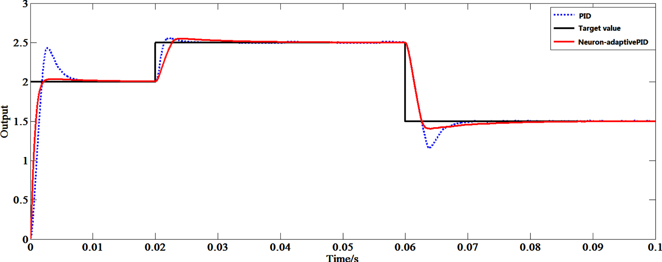
Settling time response.
Performance of controller output
The experimental platform is shown in Fig. 10, where Fig. 10(a) is the electromagnetic clutch and Fig. 10(b) is a rapier loom. Spindle encoder with 8-bit accuracy.
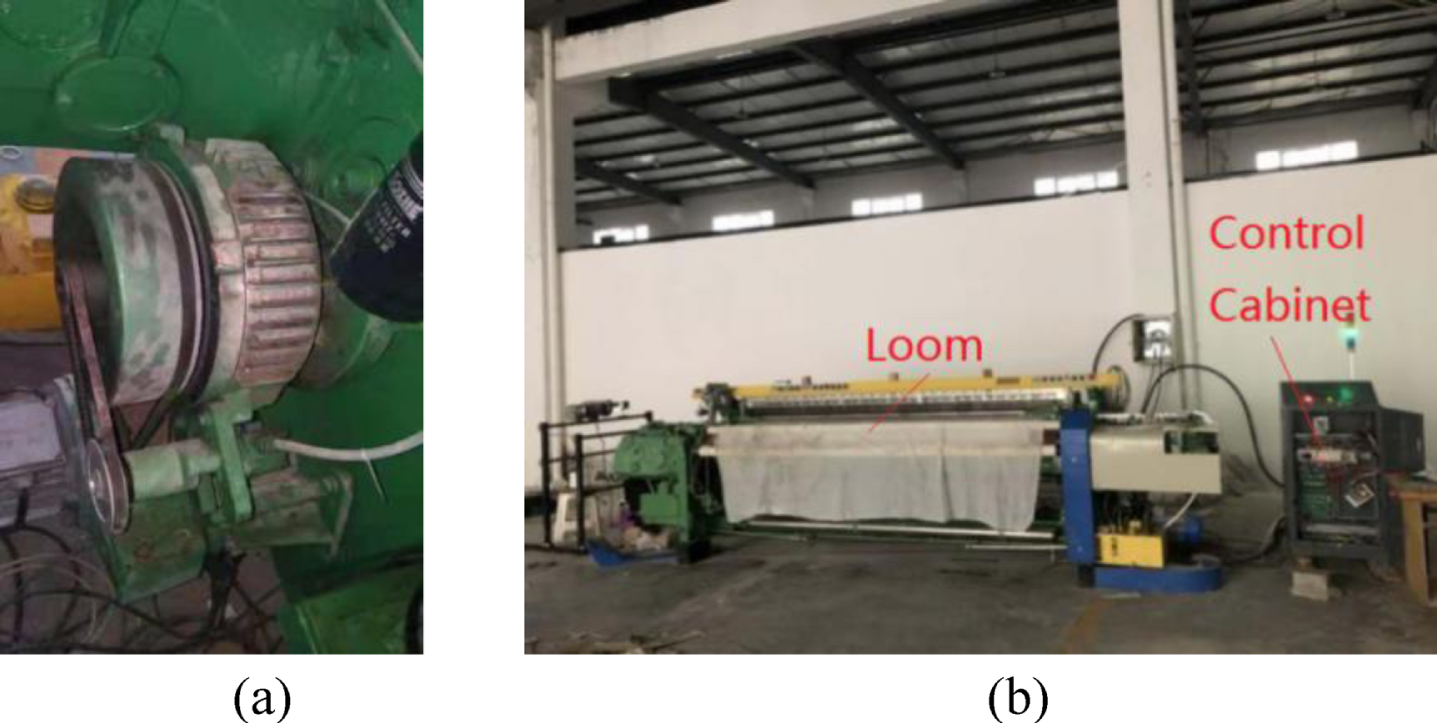
Experimental platform.
The configuration list of the loom is shown in Table 2.
To verify that the controller has good speed and angle tracking characteristics, two sets of experiments were performed. In one set of experiments, the target angle was set to 310°, and the spindle speed started from 310 rpm, increased by 10 rpm each time, and finally increased to 400 rpm. A total of 100 braking experiments were performed. In another group of experiments, the spindle speed was set to 400 rpm. The spindle angle started from 0°, increased by 40° each time, and finally increased to 320°. A total of 90 braking experiments were performed. As shown in Fig. 11, the experimental data is displayed and stored by the HMI (Human Machine Interface).
Parameters of rapier loom in experiment

Data display and storage interface of HMI.
When the target angle is unchanged, the experimental data of changing the spindle speed is shown in Table 3.
Angular error statistics of unchanged target angle
According to the data in Table 3, the maximum values of the angular error are 5°, and the average values are 2.2°. Most of the angular error values are distributed over 1–4°. This shows that the controller can meet the accuracy requirements in a large speed range.
When the spindle speed is unchanged, the experimental data of changing the target angle is shown in Table 4.
Angular error statistics of unchanged spindle speed
According to the data in Table 4, the maximum values of the angular error are 6°, and the average values are 2.8°. In some cases, the error of the target angle is large, such as 0°, 320°, but the maximum error is still within the allowable range. The experimental results show that the control algorithm can realize the adaptive control of braking angle.
For clutch control system, it is difficult to realize fast and accurate control because of its time-varying and nonlinear characteristics. By analyzing the clutch control process and combining the advantages of artificial intelligence control algorithm, a neural adaptive control strategy for the brake angle of loom spindle is presented. The controller can stabilize the coil current of the electromagnetic clutch of the loom, meet the requirement of effective process control of the clutch, and keep the stability of the braking process. According to the target braking angle and the spindle speed, the controller can also realize the adaptive control of braking angle. The experimental results show that the maximum error of braking angle is 6° and the average error is within 3°. The angle error is within the allowable error range. In conclusion, the braking angle control of loom spindle based on neuronal adaptive control can realize the adaptive control of braking angle without manual intervention, and the control accuracy is high, which can meet the control requirements of loom braking.
Conflicts of interest
The authors declare that they have no conflicts of interest to report regarding the present study.