
Abstract
The stability of unmanned vehicle is related to the safety of the vehicle itself. In the process of unmanned vehicle control, there will be collision phenomenon in the process of meeting the vehicle. To solve the above problem, the design of unmanned interaction system based on visual cognition is proposed. The hardware structure of the system is designed based on 80C51 single chip microcomputer, including ARM processor, GPS receiving module, driving record signal collecting module, etc. The PID controller design based on neural network is optimized, and the design of unmanned interactive system based on visual cognition is completed. Experimental results show that the designed system can identify the surrounding environment in real time, make corresponding decisions, let the vehicle avoid the wrong vehicle operation, and save Oil consumption.
Introduction
Machine vision cognitive unmanned system can obtain a wide range of rich environmental information. Compared with GPS unmanned system, it has lower cost and higher flexibility. According to different image processing methods, visual cognitive unmanned driving methods can be divided into monocular visual unmanned driving and binocular visual unmanned driving [1]. One of the great significances of the development of driverless vehicle technology is the improvement of traffic safety. It is important to study the development of driverless vehicle technology [2, 3].
As one of the important directions to solve the traffic safety problems in the future, the unmanned driving technology has made a series of achievements and gradually expanded to the civilian field. Zhang et al. put forward the research of UAV driver’s automatic decision-making knowledge base management system [4]. The UAV driver’s automatic decision-making knowledge base is composed of a group of knowledge models, which support knowledge representation and reasoning. Based on WEB visual knowledge modeling tools and visual knowledge service tools, the UAV driver’s autonomous decision-making knowledge base management system is constructed. The reasoning example shows that the knowledge base management system can effectively improve the efficiency of knowledge acquisition, representation and maintenance of the autonomous driving decision system. Martínez and Jim
Due to the poor interactive performance of the current driverless system, the performance of driverless vehicles decreases. Therefore, this paper takes solving this problem as the research goal, and designs a driverless interactive system based on visual cognition. In order to solve the problems existing in the traditional system, improve the comprehensive performance of driverless vehicles and promote the further development of driverless field.
Hardware design of unmanned interactive system
Light acts on visual organs to excite sensory cells, and its information is processed by the visual nervous system to produce vision. Through vision, people and animals perceive the size, brightness, color and movement of external objects, and obtain various information of great significance to the survival of the body. Vision is the most important way for human beings to obtain external information and recognize external things. After years of research, great progress has been made in the study of visual information pathway and the function of each region of visual cortex, and some mature theories have been formed. For example, the imaging mechanism of retina, receptive field mechanism, hierarchical information processing of visual cortex, functional column structure, visual cognitive psychological principle and so on. These mature biological theories are very worthy of reference for computer vision researchers, and also provide evidence and inspiration for the development of other related fields. In particular, the research on the computable model of vision is not to “clone” the human vision system, but to consider how to use the physiological characteristics of human vision to better establish and improve the performance of computer vision, so as to promote the development of related industries faster. Based on this, this paper designs the system hardware module according to the principle of visual perception, so as to improve the performance of data acquisition and processing.
Hardware architecture of unmanned interactive system
The system hardware mainly includes ARM processor, GPS receiving module, driving record signal acquisition module, visual cognition module, interface module, memory, on-board network, alarm module, etc. [7]. The hardware structure is shown in Fig. 1.

Hardware architecture of an unmanned interactive system.
ARM processor is the first RISC microprocessor with low power consumption and cost designed by acorn Co., Ltd. The full name is Advanced RISC Machine. ARM processor itself is a 32-bit design, but it is also equipped with 16 bit instruction set. Generally speaking, it can save 35% compared with the equivalent 32-bit code, but it can retain all the advantages of 32-bit system, improve data acquisition and processing, and provide technical support. Unmanned interaction system based on visual cognition is mainly used to complete the real-time release of the information and data of autonomous vehicle operation and unmanned information within the vehicle network, save the data of engine output in the process of automobile work, and collect other vehicle information data at the same time, so as to provide the vehicle owners within the vehicle network with the vehicle information query service and reduce the workload of the after-sale department [8, 9]. Therefore, the detailed realization of the unmanned interaction system based on visual cognition mainly depends on good demand analysis, and the system requirement analysis structure chart is described in Fig. 2.
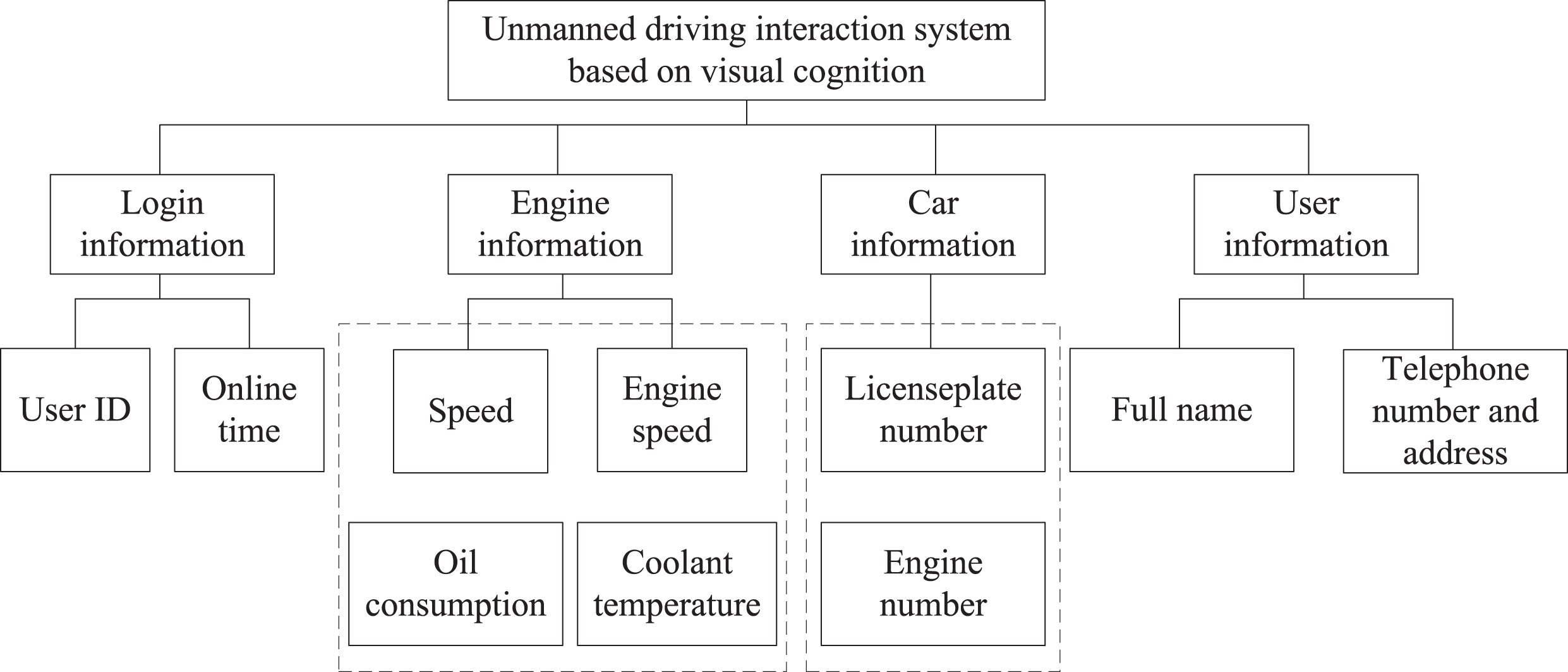
System requirements analysis structure diagram.
Based on the hardware design of the whole unmanned interactive system, the core part of the system is studied and designed by using visual cognition technology, and the driving behavior features are extracted, and the key component factors affecting the driving behavior are obtained according to the driving behavior features and the traffic safety survey results [10]. Through analytic hierarchy process to the main factor decision-making weight research, compares the different factor the key degree, carries on the quantification processing to it, constitutes the judgment matrix [11]. The collected driving information is compared, and the comparison judgment matrix A = (a ij ) k×k is established, in which a ij = f (s i , s j ) is the comparison function, The comparison function is described in Table 1, and On this basis, the weight vector W can be determined according to some criteria.
Reference table of grading scale
Reference table of grading scale
The corresponding weight values of different indexes of the judgment matrix are obtained by the multiplication root method. Assume that the judgment matrix k of order A is:
The weight is calculated by product square root method: multiplying different row elements with M i (i = 1, 2, ⋯ , k); opening M i to k power to obtain a i , that is, the geometric average value of different row elements; all elements are normalized to obtain the weight coefficient of the signal W i .
According to the obtained component factors of driverless behavior, the driving information to be collected is obtained, and the influence degree of different component factors on driving behavior is obtained [12]. According to Table 1, the importance comparison Table of collecting component factors of driverless behavior on deviation driving behavior is established, as shown in Table 2.
Deviation driving information grading and proportional scale table
Table 2 is converted to the corresponding judgment matrix A, and each column vector of matrix A = (a
ij
) n×n is normalized to obtain
According to the above formula, the output result is the result of driverless behavior recognition after the driverless characteristics are obtained. Finally, the hardware design of the driverless interaction system is realized.
The overall structure of the software design of the unmanned driving interaction system based on visual cognition is described in Fig. 3, which takes 80C51 single chip microcomputer as the core, mainly including communication serial port, voice module, display module, storage module and power module. The single chip microcomputer contains software part, and the comprehensive shift model and engine numerical model are embedded in the software in the form of programming, so as to realize the design this paper introduces the design of fuel saving assistant driving system of automobile [13].
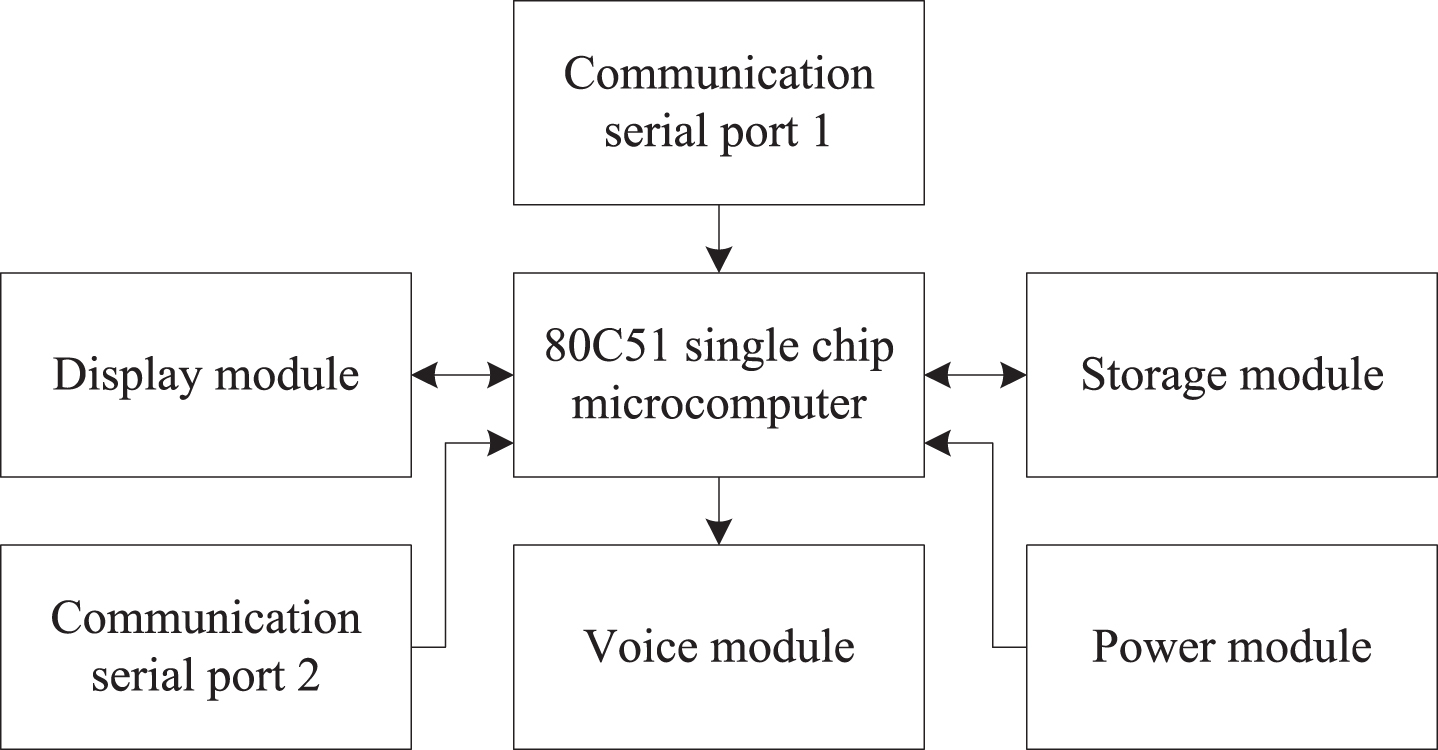
Software structure of unmanned driving interaction system.
In Fig. 3, serial port 1 interacts with sensors responsible for collecting driving information to obtain driverless vehicle information [14]. Serial port 2 exchanges information with the sensor responsible for positioning to obtain position information of the driverless vehicle. After the collected information is transmitted to 80C51 SCM, the result is transmitted in the form of voice broadcast and display through the software part of SCM to save fuel [15].
The shift law for the purpose of optimal power performance and the shift law for the purpose of optimal economy are both special shift laws. Generally, the driver will take these two characteristics into consideration for driving [16].
The comprehensive shift schedule is controlled by the consideration factor μ. For the consideration factor μ, the formula is as follows:
In the formula, the consideration factor μ ∈ [0, 1]; u j represents the optimal economic shift point; u d represents the optimal dynamic shift point; u represents the shift point of the consideration shift law.
According to formula (3), the shift point of the optimal shift law can be determined:
According to the formula (4), when u = 0, the obtained shift point is the economic shift point; when u = 1, the obtained shift point is the dynamic shift point; when 0 < u < 1, it is the shift scheme including the power, economy and the driver’s idea.
For the determination of shift point, it is necessary to quantify the factor u. The consideration factor u is a parameter reflecting the road condition and the driver’s idea. In order to quantify the consideration factor u, it is necessary to quantify the human vehicle environment in advance.
The real-time coincidence rate of driverless vehicle engine can be determined by on-board automatic diagnosis system. When the rotation rate reaches a certain value, the ratio of power to output torque will be equal [17]. At any time, the output torque of the driverless vehicle engine is equal to the maximum torque that can be output at this rotation rate. According to the characteristics of the driverless vehicle engine and the load rate of the on-board self diagnosis system, the output torque of the vehicle is calculated. Through the existing driving force and the acceleration of the driverless vehicle at this time, the running resistance f of the vehicle can be calculated. The running resistance can reflect the road conditions and can be calculated by the following formula:
In the formula, f represents the running resistance of the driverless vehicle in the actual driving process; Q t represents the torque on the external characteristic curve corresponding to the engine rotation rate of the driverless vehicle; η g represents the transmission ratio of the driverless vehicle; η0 represents the transmission ratio of the driverless main reducer; γrepresents the transmission efficiency of the driveline; R represents the wheel radius of the driverless vehicle; L f represents the load rate; ɛ represents the no load rate Rotation mass conversion coefficient of driverless vehicle; M c is the mass of driverless vehicle; a c is the acceleration of driverless vehicle [18].
Based on the previous empirical formula, the running resistance of the vehicle on normal road conditions is calculated:
In the formula, G c is the gravity of the driverless vehicle; τ is the rolling resistance coefficient of the road under this road condition; ψ is the coefficient of no air resistance; S is the windward area; ϑ c is the speed of the driverless vehicle.
The slope resistance f
r
is calculated:
The relative running resistance of driverless vehicle reflects the road condition. In order to determine the corresponding shift point, the road condition coefficient k is introduced:
In the formula, c1 is equal to 0; according to the requirements of highway design, the maximum slope of micro hill is 4%, so e1 takes the resistance value corresponding to 4% slope. When the equivalent gradient does not exceed 0, the economic shift law is adopted; when the equivalent gradient exceeds the maximum gradient, the dynamic shift law is adopted.
In order to reflect the driver’s idea, the dynamic factor λ is introduced, and the dynamic factor λ is set by the acceleration:
In the formula, let c2 equal 0 and e2 equal 2. When the acceleration is lower than 0, the economic shift rule is adopted; when the acceleration is more than 2 m/s2, the dynamic shift rule is adopted.
After quantifying the road information, the weighted consideration coefficient μ is assigned by the road condition coefficient k and dynamic performance factor λ. The formula is described as follows:
In the formula, x and y are successively used to describe the weighted values of dynamic factor and road coefficient, x, y ∈ [0, 1], and x + y = 1. Different values of x and y are given to change the influence of road conditions on the shift schedule.
The system structure block diagram of neural network adaptive PID controller optimized by visual cognition technology is shown in Fig. 4, including the optimization section of classical PID controller, BP neural network and quantum genetic algorithm.
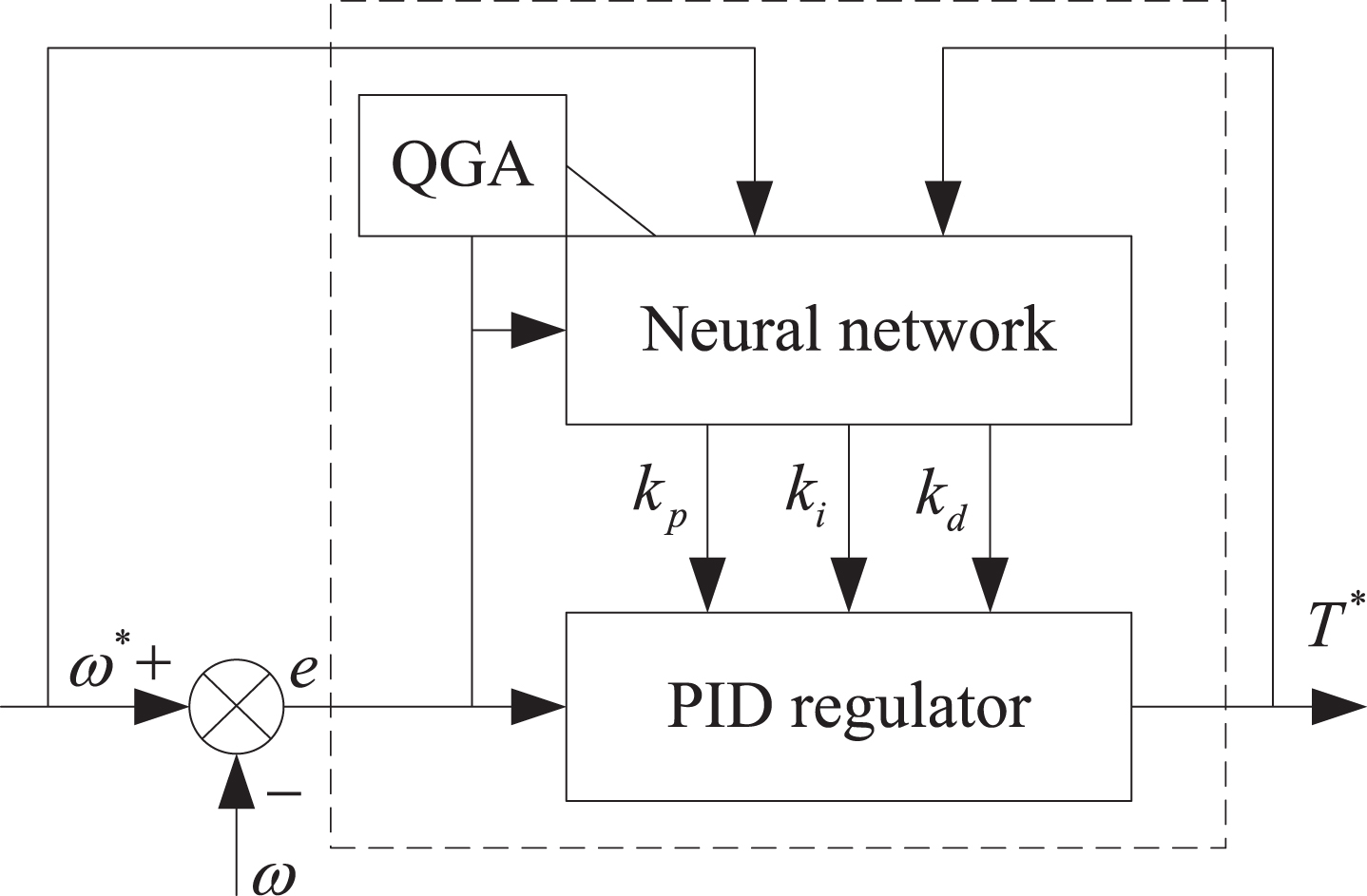
Schematic diagram of PID controller design.
The specific method of Neural Network Optimization PID control algorithm based on visual cognition technology is as follows: According to the structure of BP neural network, there are four input nodes, five hidden nodes and three output nodes. Through quantum genetic algorithm, the optimal initial values of weighting coefficient e (k) is calculated by randomly selected ω* and ω; ω* (i), T (i) and e (i) are dimensionless processed to get the input of neural network; According to the input and output calculation of each node of the neural network, the three nodes of the output layer are the three parameters k
p
, k
i
and k
d
of the corresponding PID controller; Quantum genetic algorithm is used to modify the weighted value of neural network; Let k = k + 1, return to step 2 and repeat. According to the population optimization of visual cognitive technology, the optimal transformation requirements are obtained, and the optimal weights of PID controller are obtained, namely proportional gain, integral gain and feedforward gain.
To sum up, the software design of unmanned driving interaction system is completed.
To verify the effect of an unmanned interactive system based on visual cognition, a circular road outside the north gate of a university was selected as shown in Fig. 5.
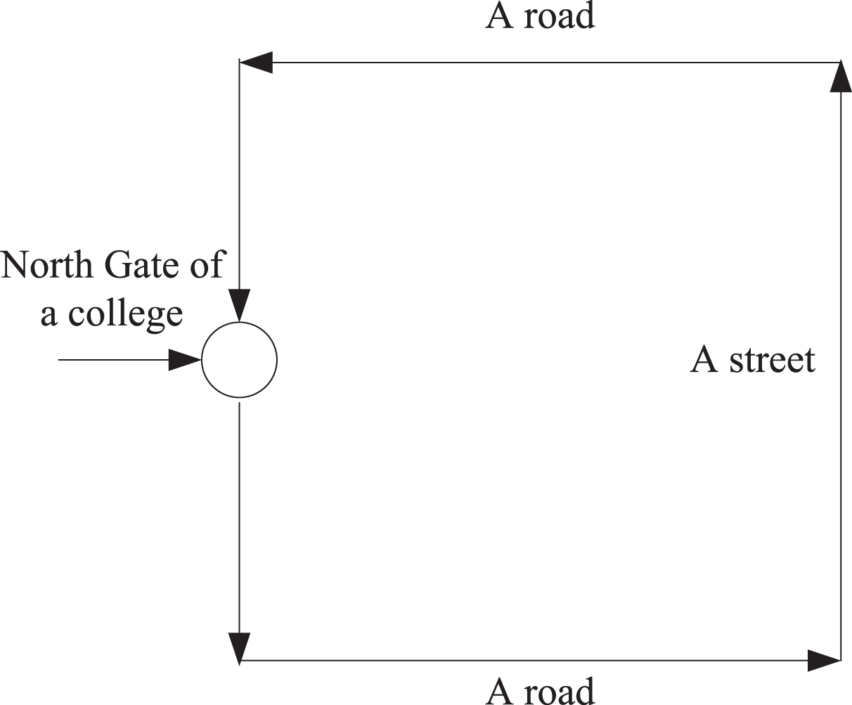
Experimental roadmap.
The core process is shown in Table 3:
Flow of evaluation indicators
It can be seen from Table 3 that the system evaluation work done in this paper is mainly to obtain relevant decision-making results by comparing different evaluation indexes, in order to lay a solid foundation for subsequent experiments.
Three driverless cars with the same amount of fuel were randomly selected and the amount of fuel was recorded before the experiment, as shown in Fig. 6.

Pre-test vehicle fuel flow.
All three cars travelled 80 km along the experimental route. One vehicle runs the present system, two others one vehicle one vehicle runs the reference [4] system, and the other vehicle runs the reference [5] system. After the whole journey, the amount of fuel in this system, ARM system and CAN system is shown in Fig. 7.
According to the comparison of the oil amount of different systems in Fig. 7, before the experiment, the oil amount of the three vehicles is the same, and the oil amount of the system running in this paper is obviously lower than that of the reference [4] system and the reference [5] system after driving along the route for 80 km, which shows that this system can achieve the goal of saving oil and the effect of saving oil is good.

Comparison results of wash oil for different systems.
After using this system, the oil consumption of 100 km at the time of deceleration is calculated and compared with the oil consumption generated without this system. The results are described in Table 4. The experimental conditions are the same as those used in this system when the oil consumption is calculated without the use of this system. Among them, 1 8 represent different fuel measurement prompt nodes.
Oil consumption statistics at the time of deceleration
According to the analysis of Table 1, the oil consumption per 100 km of the corresponding speed measurement curve after using the system is significantly lower than that without using the system, and the lowest fuel saving rate is 5.896% . That is to say, after the system prompts to decelerate, drive according to the corresponding speed and gear, so that the oil consumption is greatly reduced, indicating that the system has a good fuel saving performance [19].
The whole simulation process is as follows: when the unmanned vehicle detects the opposite vehicle, it will brake quickly and decelerate to the minimum speed 10 km/h, and the right escape position is detected. Turn right in time to avoid. After the left sensor senses the passing of the opposite vehicle, drive out and move on. The simulation live picture is shown in Fig. 8.

Simulation diagram.
It can be seen from Fig. 8 that both vehicles will decelerate and brake at the same time when running into the opposite vehicle. The unmanned vehicle decelerates to 10 km/h in 4 s, then decelerates to 5 km/h in the escape chamber. When the vehicle on the left leaves and accelerates out of the escape chamber, the speed fluctuation of the vehicle is more stable and the relative speed is more reasonable. The same contra-vehicle brakes also decelerate when it encounters an unmanned vehicle, slowing to a speed similar to that of an unmanned vehicle, and gradually speeding up after leaving the adit.
Conclusion
The unmanned interactive system based on visual cognition designed in this paper has a good tracking effect on the predetermined trajectory, and the vehicle fuel volume is significantly lower than the traditional literature system, which can achieve the purpose of fuel saving. After using the system, the fuel consumption per 100 km of the corresponding speed measurement curve is significantly lower than that when the system is not used. The minimum fuel saving rate is 5.896%, which has good fuel saving performance. The unmanned interactive system based on visual cognition can recognize the surrounding environment in real time and make corresponding decisions to ensure the safety and stability of the vehicle and avoid misoperation. Driverless vehicles can avoid obstacles, re plan new paths, and finally return to the original track [20]. However, the system in this paper also has some limitations because it does not test the interactive performance of driverless vehicles. Therefore, this problem is taken as the research goal to further optimize the performance of the system.
Prospects
Although the traditional system and the designed system have made some progress, in a short time, the driverless vehicle is still the mainstream of the world, because of the bottleneck of the interaction between the driverless vehicle and the driverless vehicle. Drivers instinctively interact with other vehicles when they are around them, including estimating and responding to the intentions of other vehicles. But the ability of driverless cars is still relatively weak, and it cannot make a socially acceptable response to other social vehicles, so the driverless cars drivers cannot understand the behavior of driverless cars in actual driving, so it is easy to lead to dangerous situations. Manned vehicle and unmanned vehicle are mixed in the traffic scene. How to realize the interaction with manned vehicle and pedestrian is a difficult problem in developing unmanned vehicle technology. Therefore, in order to realize the goal of putting driverless cars into real use, driverless cars must be able to interact with other vehicles and pedestrians in a social way. The key to the realization of the autonomous vehicle interaction capability lies in the estimation of the driving intentions of other social vehicles (not distinguishing between manned and unmanned vehicles) and the corresponding control decisions. Future research is as follows:
More in-depth study is needed to study the impact of various factors such as light intensity, ground flatness, etc. on unmanned driving interaction, and then adjust to a more applicable unmanned driving control strategy.
No other algorithm has been used for comparative experiments, and the driving strategies of vehicles may be improved and strengthened in combination with multiple algorithms in the future.
Due to the limitations of the model, the real trackless rubber-tyred vehicle cannot be simulated in detail. In the future, it is necessary to transform the real vehicle to verify the actual driving effect of the control strategy.