
Abstract
In view of the disadvantages of the existing pose estimation algorithm, which has low real-time performance and the positioning accuracy will be greatly reduced in dynamic scene, a compound deep learning and parallel computing algorithm (DP-PE) is proposed. The detection algorithm based on deep learning is used to detect dynamic objects in the environment, and the dynamic feature points are removed before the matching of feature points to reduce the impact of dynamic objects on the positioning accuracy; A method for distinguishing “pseudo-dynamic objects” is proposed to solve the problem that the stationary vehicles and pedestrians in the environment are regarded as dynamic objects. The parallel computing framework for feature point extraction and matching is established on CPU-GPU heterogeneous platform to speed up DP-PE; In the localization part of DP-PE, we propose a 3D interior point detection strategy to achieve parallel search of map points, and the saturated linear kernel function is used to act on reprojection error to realize the parallelization of pose optimization. We verify the algorithm on KITTI dataset, the experimental results show that average speedup ratio of feature point extraction and matching is 6.5 times, and the overall computational efficiency of DP-PE is about 7 times higher than that before acceleration, which can realize high precision and efficient pose estimation in dynamic scene.
Introduction
Visual pose estimation is the technology that takes camera as the main sensor to collect image information for realizing the motion carrier positioning. Visual pose estimation methods are mainly divided into Visual Odometry (VO) and Visual Simultaneous Localization and Mapping (VSLAM). VO restores the camera’s pose and estimation through an ordered image sequence [1]. VSLAM is the system that adds map construction and loop detection on the basis of VO, which can simultaneously realize the robot’s pose estimation and map construction. Since both VO and VSLAM can realize carrier positioning, this paper does not make a strict distinction between the two concepts. Visual sensors have the advantages of low cost and abundant data information. The scheme of realizing environmental perception based on visual information has been widely used in the fields of autonomous driving, robots, drones, mapping and so on [2–4].
The traditional visual pose estimation method is based on the assumption of static scene, which has inferior robustness in dynamic scene and the system even fails when there are many dynamic objects [5]. On the other hand, the visual-based pose estimation system has heavy computing burden [6], which makes it difficult to run in real-time in complex automatic driving scenarios. Therefore, how to improve the computational efficiency of the visual pose estimation system under the condition of limited resources is an urgent problem to be solved.
In order to reduce the impact of dynamic objects on the system accuracy, Bescos B et al. [7] used masks and multi-view geometry to process dynamic objects in the scene based on the maskRCNN network [8]. DS-SLAM [9] proposed to establish a dynamic semantic visualization model using SegNet network [10] and eliminate dynamic object feature points on the basis of rigid body kinematics theory. Both methods greatly improve the positioning accuracy and stability of the system in dynamic scenes. However, the introduction of semantic segmentation networks greatly increases the computational burden of the system, which makes it impossible to realize the real-time operation of the system. Choi et al. [11] distinguished the moving object from the static scene by the change of the depth information of the static scene and the moving object. however, the performance of the above method is not satisfactory when the moving objects in the scene have a large motion range. In ORB-SLAM [12], the author adopted an effective strategy for judging the validity of key frames and feature points. However, this method is difficult to deal with the situation that moving objects occupy a large proportion in the scene. ORB-SLAM2 [13] is one of the most widely used VSLAM algorithms in autonomous driving. It supports three modes of monocular, binocular and RBD-D, and has three threads of tracking, local mapping and loop closing. When the loop closing is detected, a fourth thread is opened for global optimization, which results in accurate positioning and high robustness in static environment. However, its operating speed is no more than 30 frames per second, and the system is sensitive to dynamic objects.
In order to improve the computational efficiency of the visual pose estimation system, PTAM [14] constructed two threads of parallel computing for tracking and mapping, and used sparse point clouds to realize VSLAM. The algorithmic idea of this system lays the foundation for the VSLAM multi-threaded acceleration system. Idris M et al. [15] paralleled the inverse depth estimation part of the pose estimation system on the Field-Programmable Gate Array (FPGA) platform. The algorithm improved the matrix multiplication into a parallel computing framework, which greatly improved the computational efficiency. However, the robustness of the system became worse when the image has rich texture and more features. Yong-Long Zhou et al. [16] realized the parallelization of scale-invariant feature transform (SIFT) with large computational complexity on the CUDA-based platform. CUDA-based SIFT algorithm can process images with a resolution of 1920×1440 at a speed of 11 frames per second, which is 60 times that of CPU-SIFT algorithm. However, the system relies on high-performance computing platform and has low robustness when running in a dynamic scene.
To sum up, how to achieve a perfect balance between high accuracy and computational efficiency is the main challenge of visual pose estimation technology. To take up the challenge, this paper proposes a new binocular visual pose estimation system based on ORB-SLAM2: DP-PE. DP-PE adopts a deep learning-based target detection algorithm to detect dynamic objects in the environment, and selects dynamic feature points based on the geometric characteristics of feature points and removes them, so that the points participating in the feature point matching are the static feature points outside the detection box or the “pseudo-dynamic feature points” inside the detection box, so as to reduce the impact of dynamic objects on the positioning accuracy of the system. Taking advantage of the GPU’s application in parallel computing to accelerate computing, a method based on parallel computing is adopted to improve the computing efficiency of the system for the modules of extraction and matching of dense feature points, map point search and local map optimization.
Overall system architecture of DP-PE.
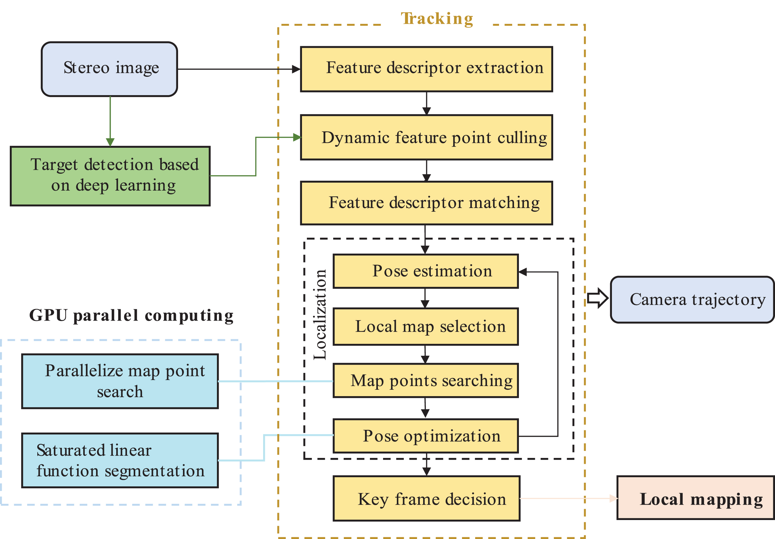
DP-PE includes three parallel threads of target detection, tracking and local mapping, as shown in Fig. 1. The target detection thread is responsible for detecting dynamic objects in the scene and passing the position parameters of dynamic objects to the tracking thread. This method can detect the dynamic objects in the driving scene, and eliminate the dynamic feature points before matching the feature points. However, it may regard the “pseudo-dynamic objects” as dynamic objects, such as stationary vehicles or pedestrians on the road. When “pseudo-dynamic feature points” account for a large proportion of all feature points in the current frame image, the number of feature points participating in matching is greatly reduced after the pseudo-dynamic feature points are eliminated, resulting in low positioning accuracy in this case; In order to solve this problem, DP-PE adopts the “ pseudo-dynamic feature point” screening method to distinguish the true and false dynamic feature points, as detailed in Section 3.
On the basis of ORB-SLAM2, the tracking thread extracts Oriented Fast and Rotated Brief (ORB) features [17] from the image. Combined with the dynamic object position provided by the target detection thread, the dynamic object feature points are removed. In this way, the candidate static waiting points are obtained, the feature points are matched and positioning is completed according to the matched feature points. The localization part includes pose estimation and BA pose optimization. After the initial pose is obtained by the localization part, the key frame is selected according to the strategy in ORB-SLAM2, and a local map is maintained by the key frame feature points. According to the initial pose obtained from the localization part, the images that have the most common viewpoints with the current image in the local map are projected to the current frame, and the Bundle Adjustment (BA) is used to calculate and minimize the reprojection error, so as to optimize the camera pose of the current frame and realize the tracking and positioning of the camera at the moment of image acquisition. In order to improve the computational efficiency of tracking threads, GPU parallel computing is designed for computation-intensive feature extraction, matching as well as localization part. The detailed process is shown in Section 4.
On the premise of satisfying the locational accuracy and considering the reduction of computational complexity, the local map is constructed by the local mapping thread. In thread of local mapping, the image that has the common cloud with the current frame image is defined as the key frame, and the frame with the most common feature points between the key frame and the current frame is called the reference key frame. The local mapping thread inserts the key frames selected by the tracking thread into the map to generate new map points. BA is used to optimize pose of the key frames in the map, and the redundant key frames in the map are removed.
Data association algorithm based on deep learning
Problems and solutions
The tracking thread extracts the ORB features from each image, calculates the hamming distance between the ORB feature points of the left and right images and matches them. The spatial position of the matched point pair is calculated according to the matching results. At the same time, the front and back frame images are also matched with feature points, and the camera pose is obtained according to the matching point positions. After the initialization, the 3D points of the left key frame image and the 2D points of the left camera image of the current frame image are estimated by Perspective-N-Point(PNP) [18]. By making full use of the matching results, BA optimization method is adopted for iterative optimization, and the optimal estimation of pose is obtained. When the extracted dynamic object feature points are matched in front and back frames, the same dynamic feature points are displaced in space, so the pose recovered by these matched feature points is inaccurate. Especially when the object moves at a high speed, the same feature points in the front and back frames have a large displacement in the real space. The position and pose recovered by these matching points are quite different from the actual situation, resulting in a significant decrease in the positioning accuracy.
For above reason, DP-PE proposes a strategy as shown in Fig. 2. While extracting ORB features, the tracking thread simultaneously detects the dynamic objects in each frame image through the target detection algorithm, and transits the detected dynamic object position information to the tracking thread, which eliminates the dynamic object feature points before feature points match. The feature points outside the detection box area obtained by the target detection algorithm are static feature points, and the feature points within the detection box area are divided into “pseudo-dynamic object feature points” (such as stationary parked vehicles or pedestrians temporarily staying at the roadside) and feature points of real moving dynamic objects. In order to make all static feature points participate in subsequent matching and optimization on the premise of limited feature points, this paper adopts a screening method of “pseudo-dynamic feature points” after the feature points extraction and target detection algorithm are completed, and judges whether the feature points in the detection box are “pseudo-dynamic feature points” or dynamic feature points by this method; Finally, the dynamic feature points are eliminated, and “pseudo-dynamic feature points” and static feature points are reserved as candidate matching points, so as to minimize the influence of dynamic object feature points on positioning accuracy.

Dynamic feature point elimination algorithm flow.
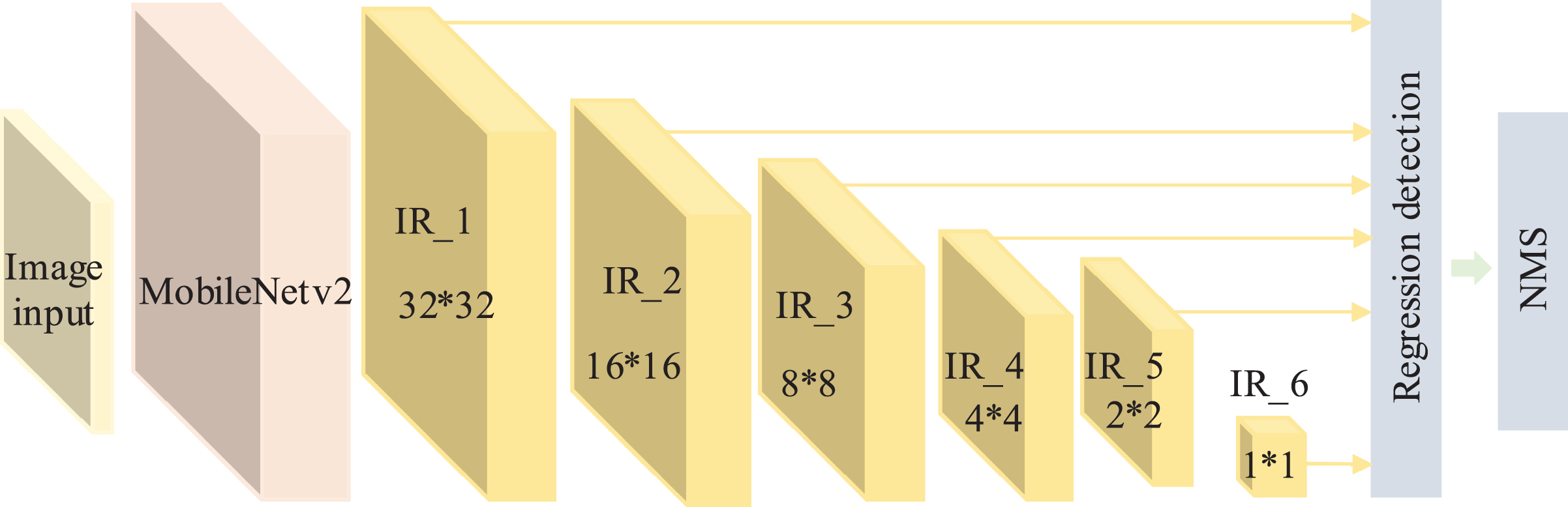
The target detection algorithm based on deep learning has been widely used in dynamic objects detection such as vehicles and pedestrians in automatic driving scenes. DP-PE introduces an improved Single Shot MultiBox Detector (SSD) [19] target detection network based on ORB-SLAM2, as shown in Fig. 3.
Improved SSD network structure.
VGG-16 [20] is replaced as the basic network layer by a lightweight MobileNetV2 network with the removal of the full connection layer and the pooling layer. MobileNetv2 is a basic network with fewer network parameters improved by Mark Sandler et al. [21] on the lightweight convolutional neural network MobileNet [22], and at the same time, the convolutional layer in SSD is replaced with 6 convolutional layers composed of inverted residual blocks in Fig. 3. The inverted residual block (IR) is an improved ResNet module [23]: ResNet in MobileNetv2 is optimized, and the input is high-dimensionally converted to deep decomposition and convolution, which has a high model expression ability. Under the action of two 3*3 convolution kernels, the final feature map outputs one as the target classification result and the other as the input of regression detection. Finally, Non-maximal Suppression (NMS) is used to obtain the unique detection box.
The dataset for model training and evaluation is derived from the KITTI dataset [24]. The dataset is divided into four categories: four-wheeled vehicle, two-wheeled vehicle, pedestrian and background, and corresponding labels are made. In the stage of model learning, the results of network detection are compared with the real label values, and those with the same detection results as the real label values are marked as positive samples. At the same time, the cost function values of all samples are sorted, and images are selected as negative samples according to the size of the cost function values, and the number of negative samples is about three times that of positive samples. In this paper, four fifths of KITTI dataset is set as the training set, and the verification set and the test set account for one fifth respectively, with about 1500 images. After model training, verification and evaluation, the final target detection model is obtained.
Target detection and tracking are two parallel threads, and a mutex lock is used to ensure that no access data conflict occurs. The lock should be obtained in advance before the write operation is executed. The target detection thread and the tracking thread communicate with each other by asynchronou-sly reading and writing shared variables to maximize the use of computing resources. When image input is detected, target detection algorithm based on Convolutional Neural Network (CNN) is used to detect dynamic objects (pedestrians and vehicles), and feature point extraction algorithm is used to extract feature points of image data in parallel. Then, combining dynamic target detection results with feature point extraction results, dynamic target feature points are eliminated, and finally feature points are matched according to feature point matching algorithm.
In order to improve the robustness of the system in dynamic scenes, the pseudo-dynamic feature points in the detection box should be distinguished from the real moving dynamic feature points, and the pseudo-dynamic feature points should be retained as candidate static feature points for matching. Based on the geometric property that the spatial distance between any two points on a static object remains unchanged in course of movement, the paper proposes a method to screen “pseudo-dynamic feature points". The method divides the above-mentioned feature point sets into two categories, one is the point set outside the detection box, which is static feature point, and the other is the point set inside the detection box, which may be “pseudo-dynamic feature point” and dynamic feature point. For each detection box, select any static feature point outside the detection box and any point in the detection box to form a point pair, calculate the spatial distance of the point pair, compare the changes of the spatial distance of the point pair in front and back images, if the changes exceed a certain threshold, it shows that the objects in the detection box are dynamic objects, and all the feature points in the detection box should be eliminated, otherwise, the object in the detection box is a stationary object, and the extracted feature points are “pseudo-dynamic feature points". The feature points in the detection box should be retained as candidate points for subsequent matching.
System tracking thread time-consuming test statistics diagram.
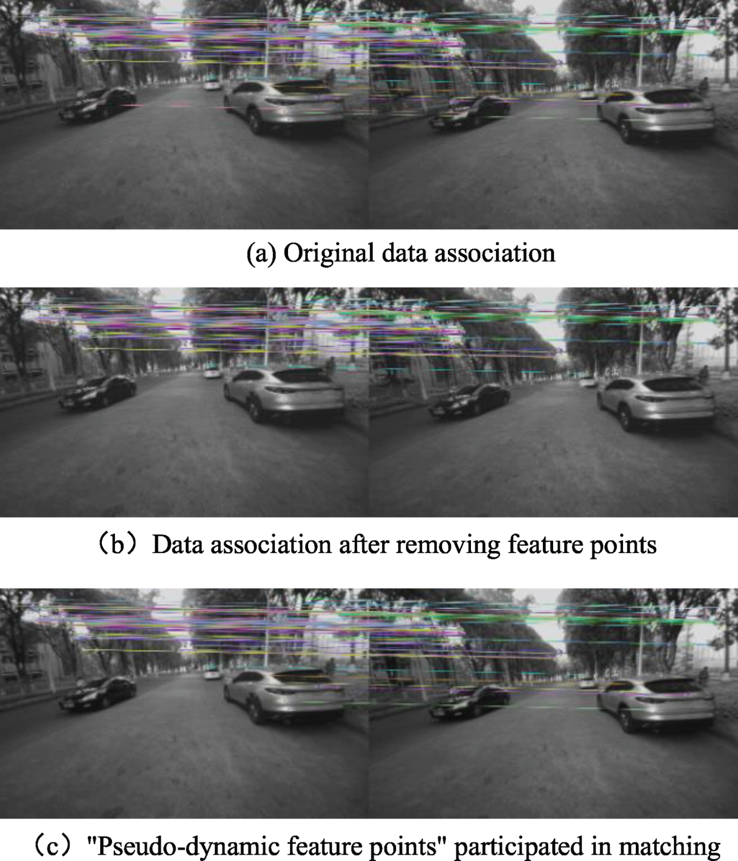
Figure 4 shows the effect comparison of this method in the actual scene. Figure 4(a) shows the data correlation of the original model before optimization and improvement, and it can be seen that both dynamic vehicle on the road and stationary vehicles on the roadside are involved in feature point matching. Figure 4(b) shows the data association after removing the detected feature points in the vehicle area by introducing the target detection algorithm based on CNN. The feature points on the stationary or moving vehicles in the picture are regarded as dynamic feature points and removed. Figure 4(c) is an effect diagram of screening out “pseudo-dynamic feature points” based on Fig. 4(b) and keeping them involved in matching. It can be seen that the data association algorithm based on deep learning in this section has an obvious processing effect on the feature points of dynamic objects, and effectively reduces the interference of dynamic objects.
Data association comparison diagram before and after removing dynamic feature points.
DP-PE calculation efficiency test and acceleration feasibility analysis
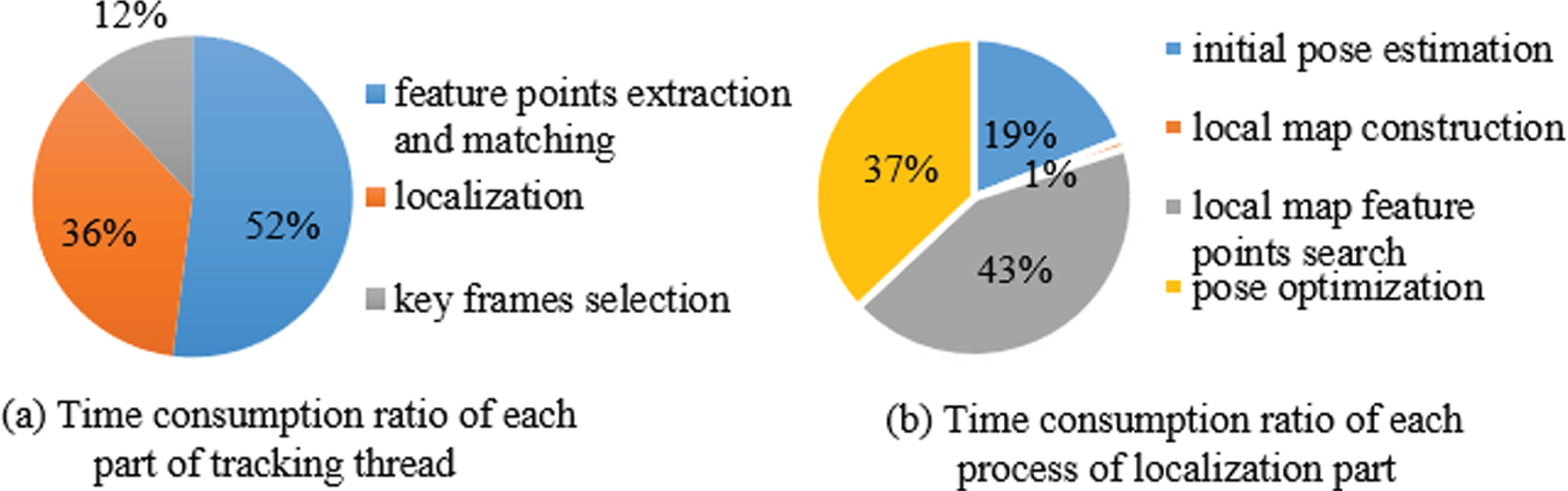
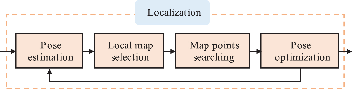
The DP-PE tracking thread is compact joined with the carrier, which requires high real-time, and the tracking effect directly affects the performance of the system. According to the time-consuming test analysis of each part of DP-PE tracking thread, as shown in Fig. 5 (a), the extraction and matching time of feature points takes up the highest proportion in the tracking thread, accounting for 52%, followed by the localization part, accounting for 36%, and the key frames selection time takes up the lowest proportion, accounting for 12%. The specific algorithm flow of DP-PE tracking thread localization part is shown in Fig. 6. The initial pose and spatial points obtained by inter-frame matching are taken as inputs, and the points within the current image view are found in the local map. The points in the visual field are projected onto the 2D plane of the current image through the initial pose transformation matrix. Combined with the matching relationship, BA is used to minimize the reprojection error of spatial points, and the pose of the current image is iteratively optimized for multiple times to realize the tracking and positioning of the camera at each moment.
DP-PE location process.
The whole process of feature point detection and matching is performed on the image, and the image is stored in the computer memory in the form of two-dimensional array. Compared with the CPU, GPU has great advantages in the operation of two-dimensional array. After the image is divided into blocks by CPU, different blocks are configured into different threads of the GPU. Different image blocks execute the same feature point detection and matching instructions in different threads, so as to realize the parallel acceleration of feature point detection and matching. The specific implementation principle is shown in Section 4.2.
Taking the image pose optimization of a frame as an example, and taking spatial points and pose as optimization variables. It is necessary to select 500∼2000 frames as local maps, search 1000∼6000 spatial points and calculate 200∼800 reprojection errors. The calculation time of each part of the localization process has been tested for several times, as shown in Fig. 5 (b), the result shows that the time of local map feature points search accounts for 43% of the overall localization time, followed by pose optimization, which accounts for 37%, initial pose estimation, which accounts for 19%, and local map construction, accounting for 1%. It can be seen that the calculation time of map point search and pose optimization accounts for 80% of the overall localization part, which has a great space for optimization, as shown in Section 4.3.
The programming model under the CUDA software architecture takes the CPU as the host end, and the GPU as the collaboration end, which also called the device side. The host program executes complex logical operations and serial calculations, while the GPU is responsible for executing highly threaded parallel tasks. In this section, under the multi-core CPU and high-performance GPU heterogeneous collaborative computing platform, the most time-consuming part of the tracking thread, that is, the extraction and matching of ORB feature points, is parallelized and accelerated.
Figure 7 shows the ORB feature point extraction and matching calculation framework based on the CPU-GPU heterogeneous platform. The specific workflow is mainly divided into the following three steps:
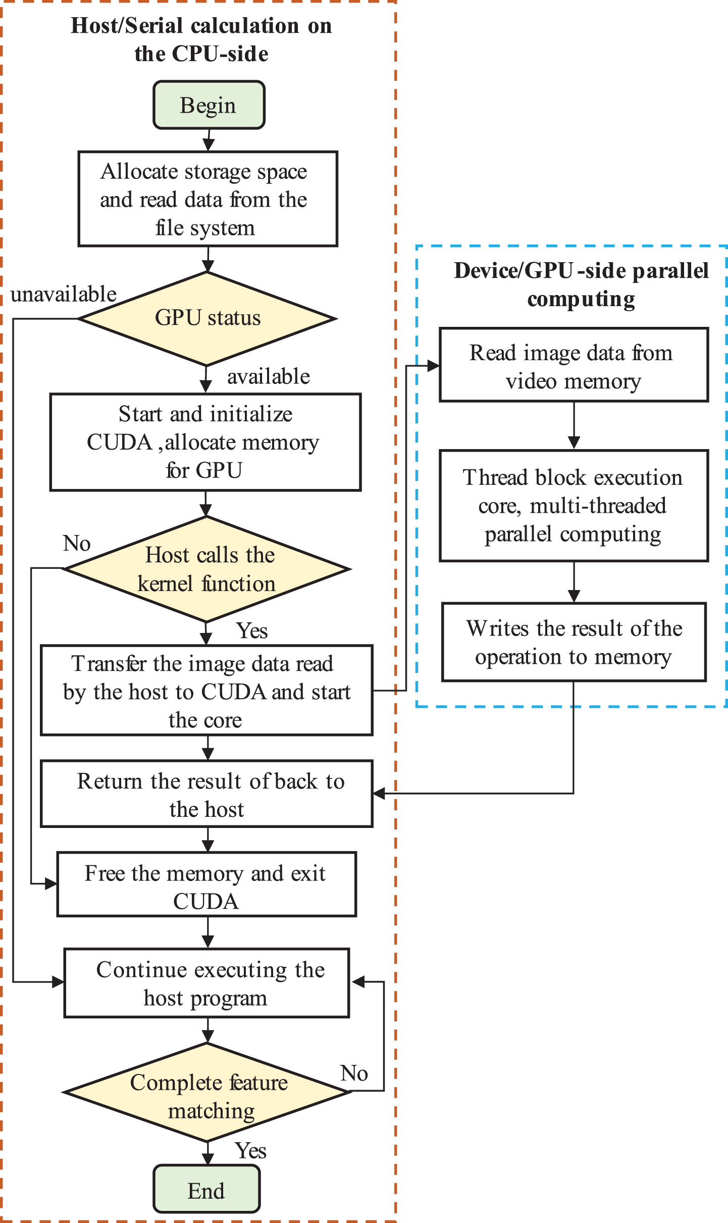
Feature point extraction and matching computing framework based on CPU-GPU heterogeneous platform.
(1) Initialization
Firstly, the CPU allocates memory to store data to be processed. The CPU reads image data from the file system and stores it in the memory, and then checks the status of GPU. If the GPU is unavailable, it continues to execute host program, and if the GPU is available, it starts CUDA and completes the initialization of CUDA architecture, and allocates video memory for GPU to execute GPU parallel computing tasks and store computing results. If the host program calls the device-side kernel function, then the CPU transfers the image data in the memory to CUDA and stores it in the GPU memory. At the same time, the host starts the kernel and enters the second step of GPU acceleration. If the host program does not call the device-side kernel function, it releases the memory allocated for the GPU and exits CUDA.
(2) Parallel Computing
After the kernel function is started, quantities of threads are generated at the device side according to the host side initialization parameters, and the image data is read from the video memory. The task scheduler at the host allocates the thread blocks on the Streaming Multiprocessor (SM) to achieve parallel operation, and the results of operation are written into the video memory for storage. The FAST corner detection, scale space generation, BRIEF descriptor calculation and feature point matching in the feature point detection algorithm are all implemented in this step.
Parallel computing process for the localization of DP-PE.
(3) Obtain the results of GPU
The above steps complete the GPU acceleration and store the results in the GPU video memory. At this time, the host end continues to work to obtain the calculation results in the video memory and store them in the memory allocated by the CPU. After the parallel computation is completed, the host releases the GPU video memory and quits CUDA. If the matching of feature points is completed, the calculation process will be ended. Otherwise, the host program continues to execute, and the above steps are repeated to accelerate the feature point matching.
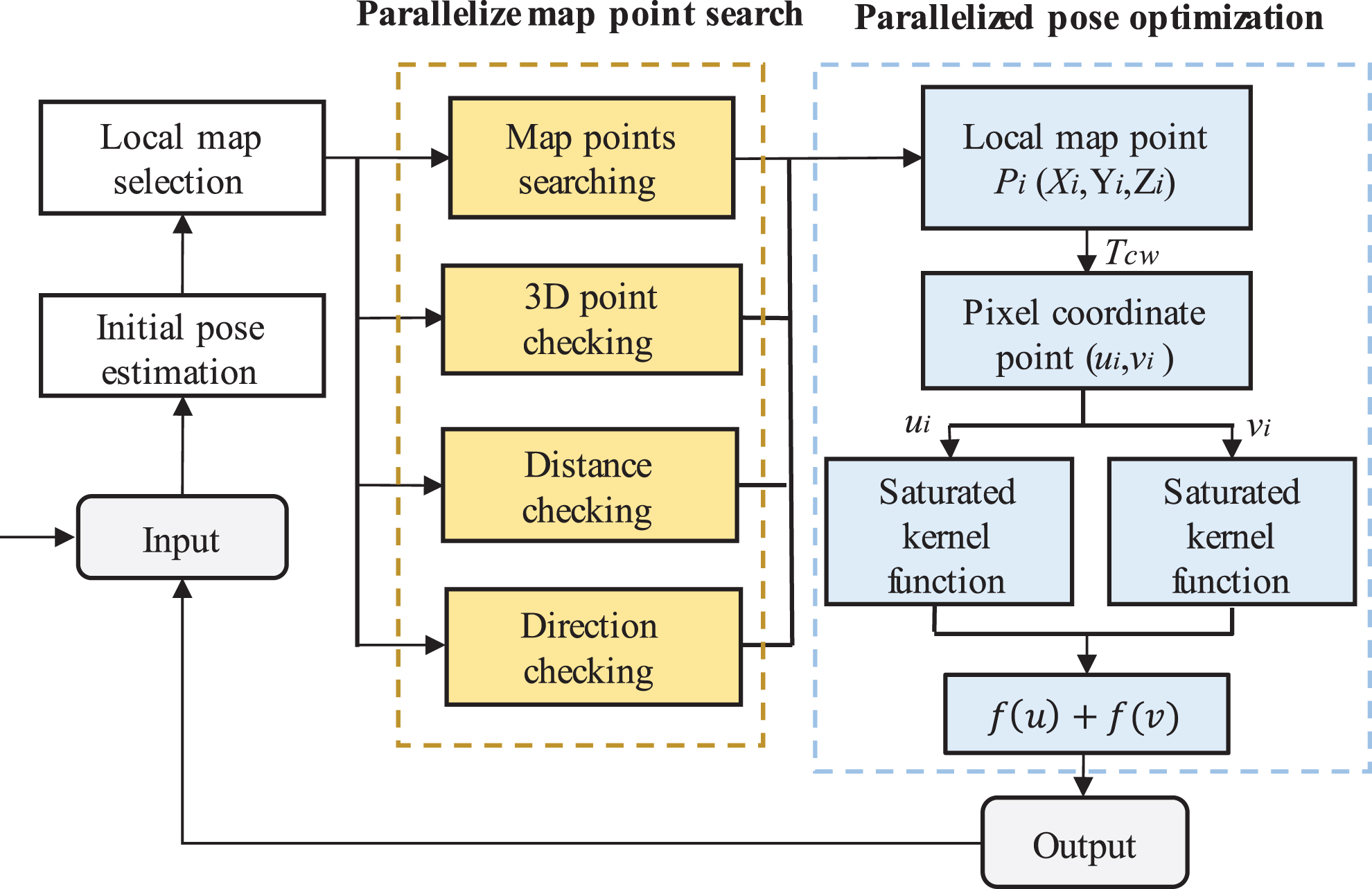
As can be seen from the analysis in Section 4.1, the computation of the localization part of the tracking thread is time-consuming. Aiming at this problem, combined with the characteristics of GPU suitable for parallel computation, the method based on parallel computing is used for the localization module to improve the system computational efficiency.
The calculation process of DP-PE localization part is shown in Fig. 8 The initial pose of the current frame obtained by inter-frame matching is taken as input. The space I centered on the camera is calculated according to the initial pose, and three criteria are used to screen map points in parallel: (1) 3D space internal point discrimination: screening out the local map point set S located in space I; (2) Direction checking: calculate the included angle between the current view ray
Since these three map point screening criteria do not rely on 2D points, local map points can be searched in parallel, and the local map point set that is projected to match the current image can be obtained through Equation (1):
Where P is the local map point set obtained by projection matching. The initial pose obtained by inter-frame matching is used to project P to the camera coordinate system, and the coordinate P
ci
of the point to be matched in the camera coordinate system is obtained:
Where [X
i
Y
i
Z
i
]T = P
i
,
Where [u i v i 1]T is the homogeneous coordinate of the world coordinate point P i in pixel coordinates, and f x , f y , c x and c y are camera internal parameters.
The point set P is projected from the world coordinate system to the pixel coordinate system and is projected to match with the feature points of the current frame. BA is used for minimum optimization, and the saturated kernel function is used to act on the sum of the squares of the two-norm of the minimum error term:
Where f
i
(x) is the residual between the coordinates of the point set P in the pixel coordinate system and the coordinates of the feature points in the current frame, S is the robust saturation kernel function, denoted by ∥f
i
(f) ∥ 2 = e, then:
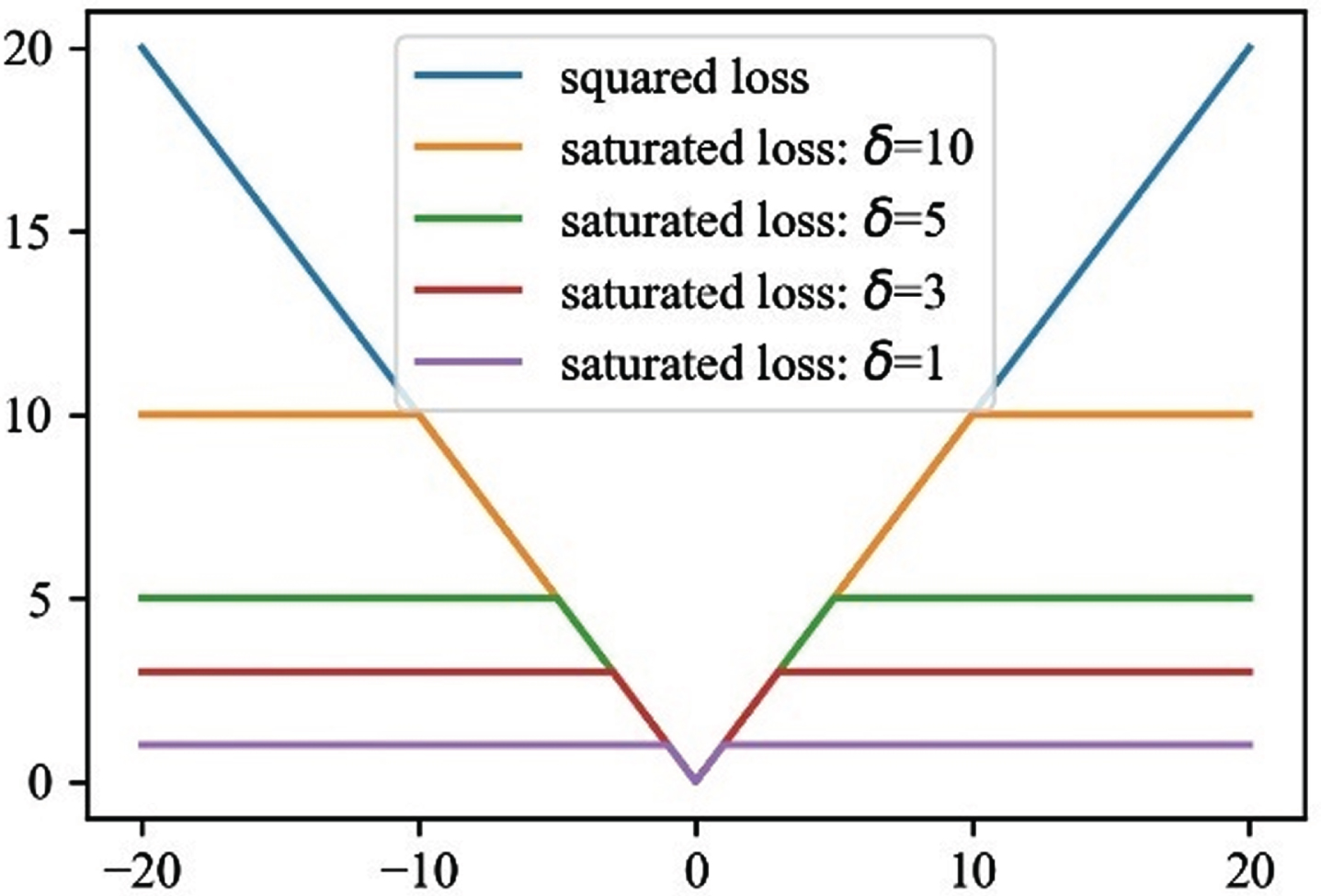
Where δ is the residual threshold. When different values are taken, the variation trend of saturation kernel function is shown in Fig. 9.
Variation trend of saturated kernel function under different residual thresholds.
According to the chi square distribution, the threshold value δ is 35.89, when the residual is less than 35.89, the function growth is one-time. When the residual error exceeds 35.89, the function value is taken δ2, which is equivalent to limiting the maximum value of the gradient. It can effectively deal with the outliers and ensure the high robustness of the system. The linear property of saturated kernel function is used:
The second-order Taylor expansion of the saturated robust kernel error function is:
Where the square of the residual is:
Substituting Equation (8) into Equation (7), we have
By summation of Equation (9) and derivation of variables, the following results are obtained:
Combined with Equation (6), the optimal pose of the current frame image can be solved, the first and second derivative of the kernel function are involved in the calculation process. It can be seen from Equation (5) that both the saturated kernel function and its derivative have good linear properties, and when the saturated kernel function are applied to multiple variables (x1, x2, ... , x
n
), the following equation are satisfied:
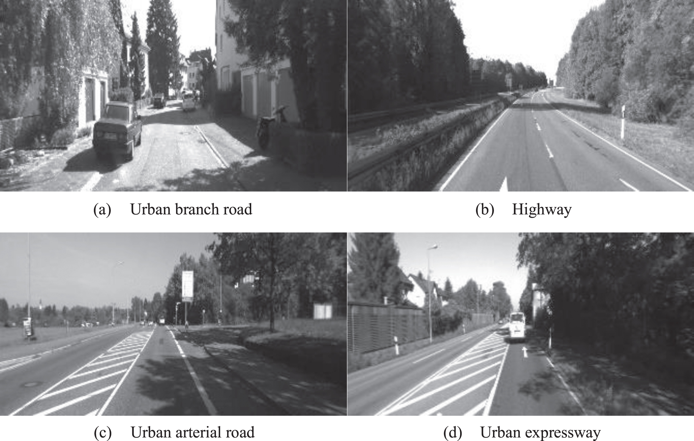
KITTI dataset road types.
Compared with the nonlinear huber kernel function, the saturated kernel function can divide the computation linearly owing to its linear properties, so as to realize the parallel computation of pose estimation and achieve the purpose of accelerating the computation. All the parallel computation is completed on the CPU-GPU heterogeneous platform.
Experimental platform and dataset
The DP-PE algorithm implementation and verification are all completed under Ubuntu 16.04 system. The main programming languages are C++ 11 and Python 3.6. In order to improve the programming efficiency of DP-PE, the algorithm API is encapsulated on the basis of ROS, and the parallel computing of GPU is realized based on CUDA9.0 programming. The detailed configuration parameters of the algorithm experimental platform are shown in Table 1.
Experimental platform parameters
Experimental platform parameters
The 00∼10 sequence datasets with the true value of the trajectory in KITTI visual odometer are selected divided into four categories according to road types. As shown in Fig. 10, the dataset is the large-scale real environment collected by the camera on the fast-moving vehicle. The environment contains dynamic objects such as moving vehicles and pedestrians, which can well evaluate the performance of DP-PE algorithm.
Absolute Pose Error (APE) or Root Mean Square Error (RMSE) are used to evaluate the testing accuracy of different algorithms on the same dataset. As shown in Equation (12), APE is commonly used to represent the absolute trajectory error, which is the difference between the estimated value and the real value, and can better measure the global consistency of the trajectory. As shown in Equation (13), RMSE is the square root of the ratio of the square of the deviation between the predicted value and the true value to the number of observations N, which can better reflect the deviation between the observed value and the real value.
Where
Where y
i
is the true value,
The state of the art ORB-SLAM2 and VINS-Fusion without loop closing threads and DP-PE are tested on KITTI. Taking the test on KITTI 01 dataset as an example, Figs. 11 and 12 respectively show the position and attitude comparison results of DP-PE algorithm and ORB-SLAM2 on KITTI 01. The position is represented by X, Y and Z coordinates, and the attitude is represented by Euler angle. It is easy to know that the trajectory and attitude measured by DP-PE and ORB-SLAM2 are relatively close to the true value.
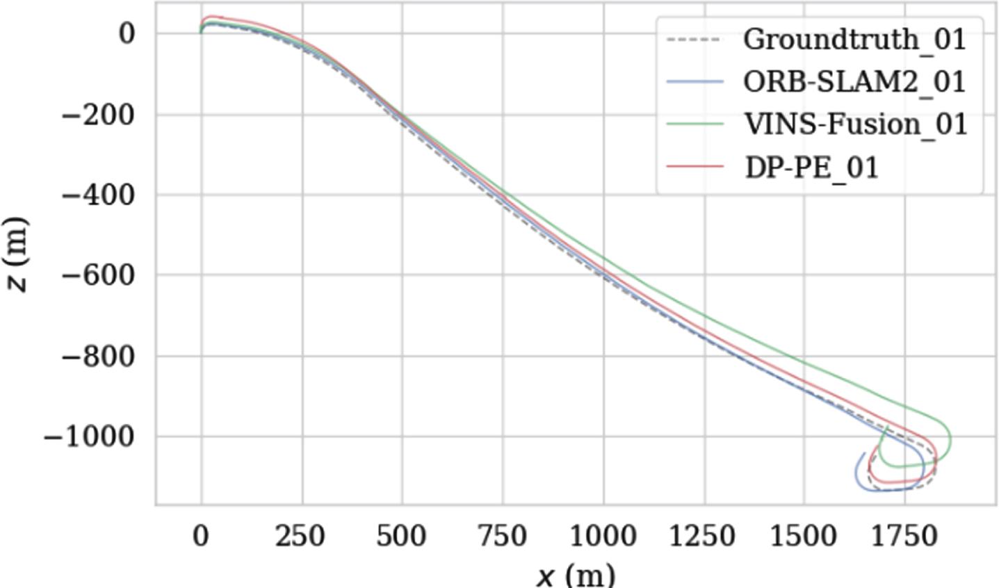
Comparison of trajectories on the KITTI 01.

Comparison of attitude angle estimation on KITTI 01.
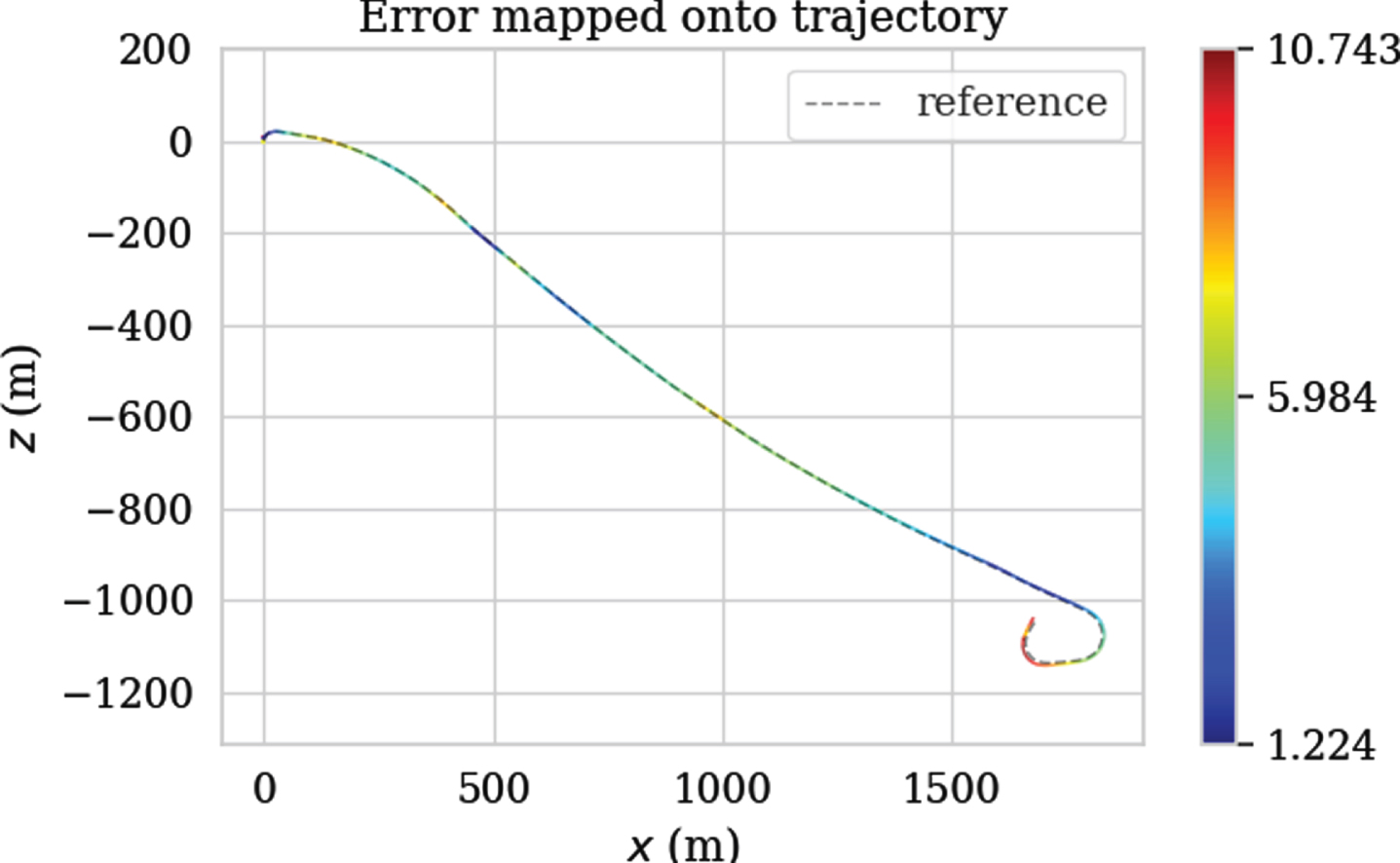
Figures 13, 14 and 15 show the APE changes with the index of the image sequence and the APE mapping trajectory obtained by ORB-SLAM2, VINS-Fusion and DP-PE tested on KITTI 01 respectively. The color changes on the trajectory can directly reflect the APE changes of ORB-SLAM2, VINS-Fusion and DP-PE measured on KITTTI 01. Different colors represent different APE values. The closer to red, the larger the APE is, and the closer to the blue, the smaller the APE is. Therefore, it can be clearly seen from the figure that the APE of DP-PE has a smaller variation range with time series than the other two algorithms, which reflects that DP-PE has better stability than ORB-SLAM2 and VINS-Fusion; Fig. 16 shows the overall distribution of APE obtained by the three methods in the KITTI 01 test, which shows that DP-PE is obviously improved compared with ORB-SLAM2 and VINS-fusion in APE indicators. Meanwhile, the RMSE of ORB-SLAM2, VINS-Fusion and DP-PE are 11.075, 5.808 and 1.549 respectively. In conclusion, the test accuracy of DP-PE on KITTI 01 is significantly higher than that of ORB-SLAM2 and VINS-fusion.
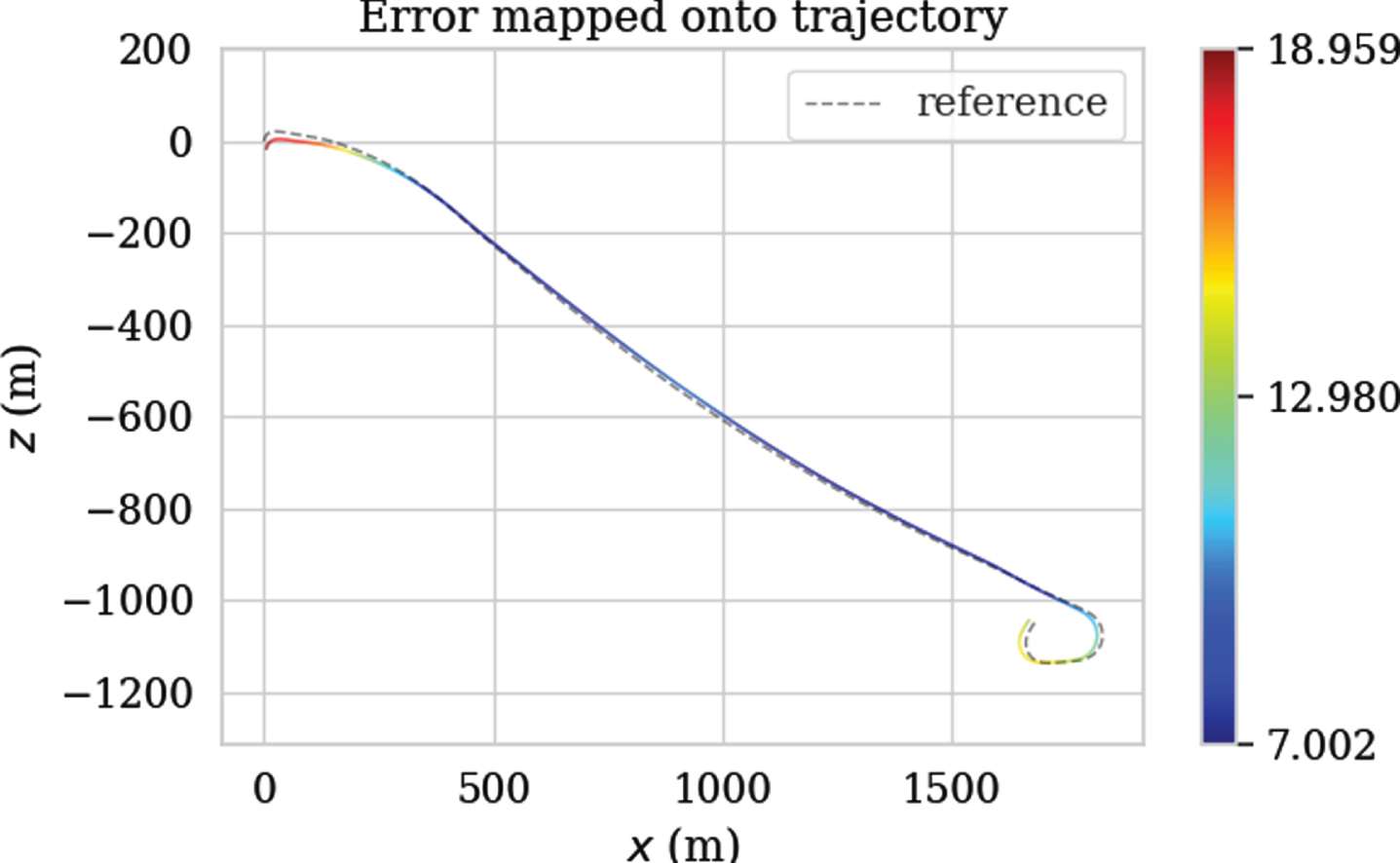
The trajectory error of ORB-SLAM2 tested on the KITTI 01.
The trajectory error of ORB-SLAM2 tested on the KITTI 01.
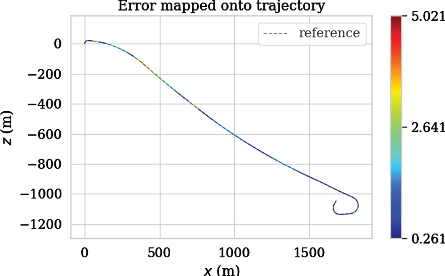
The trajectory error of ORB-SLAM2 tested on the KITTI 01.
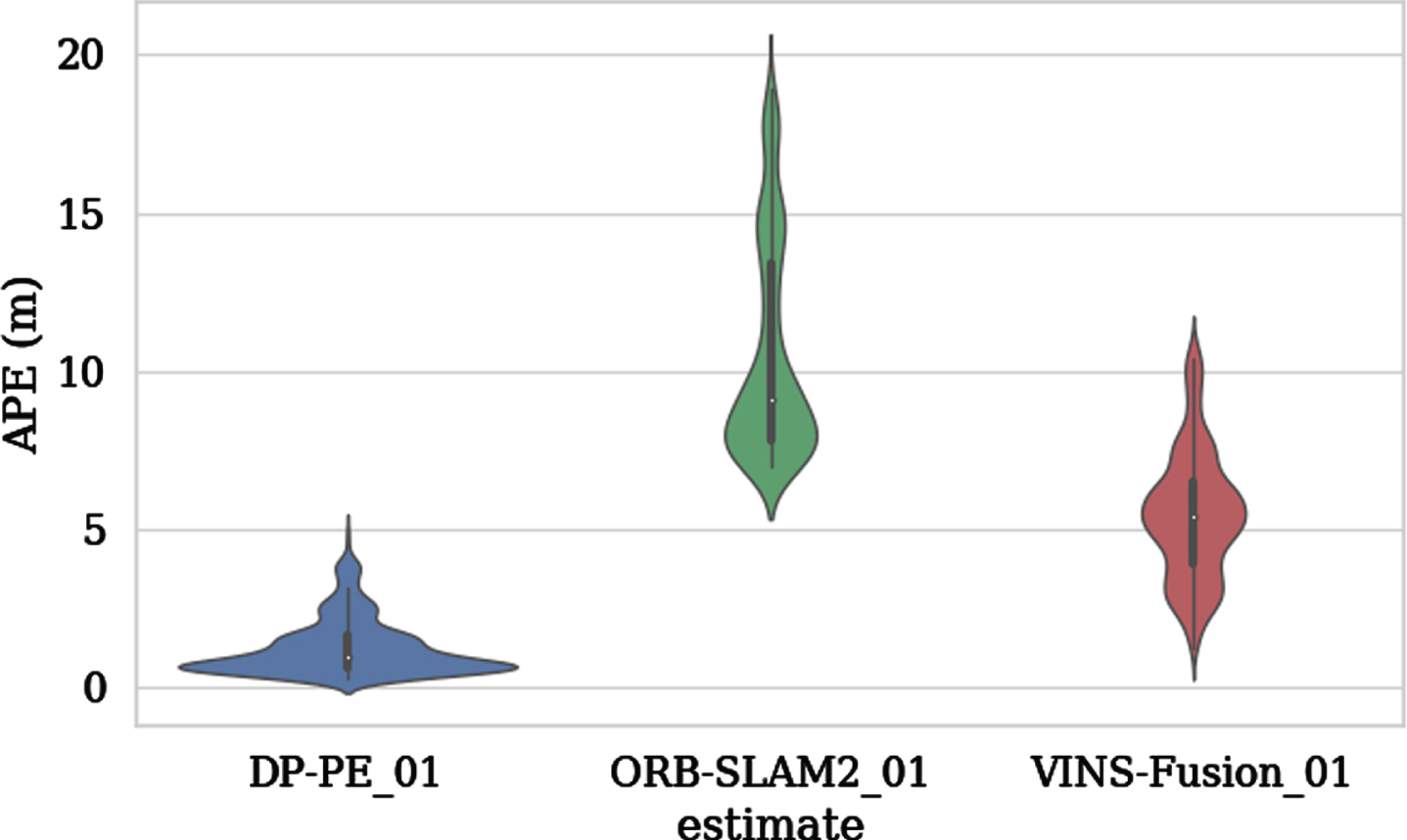
APE violin diagram tested on the KITTI 01.
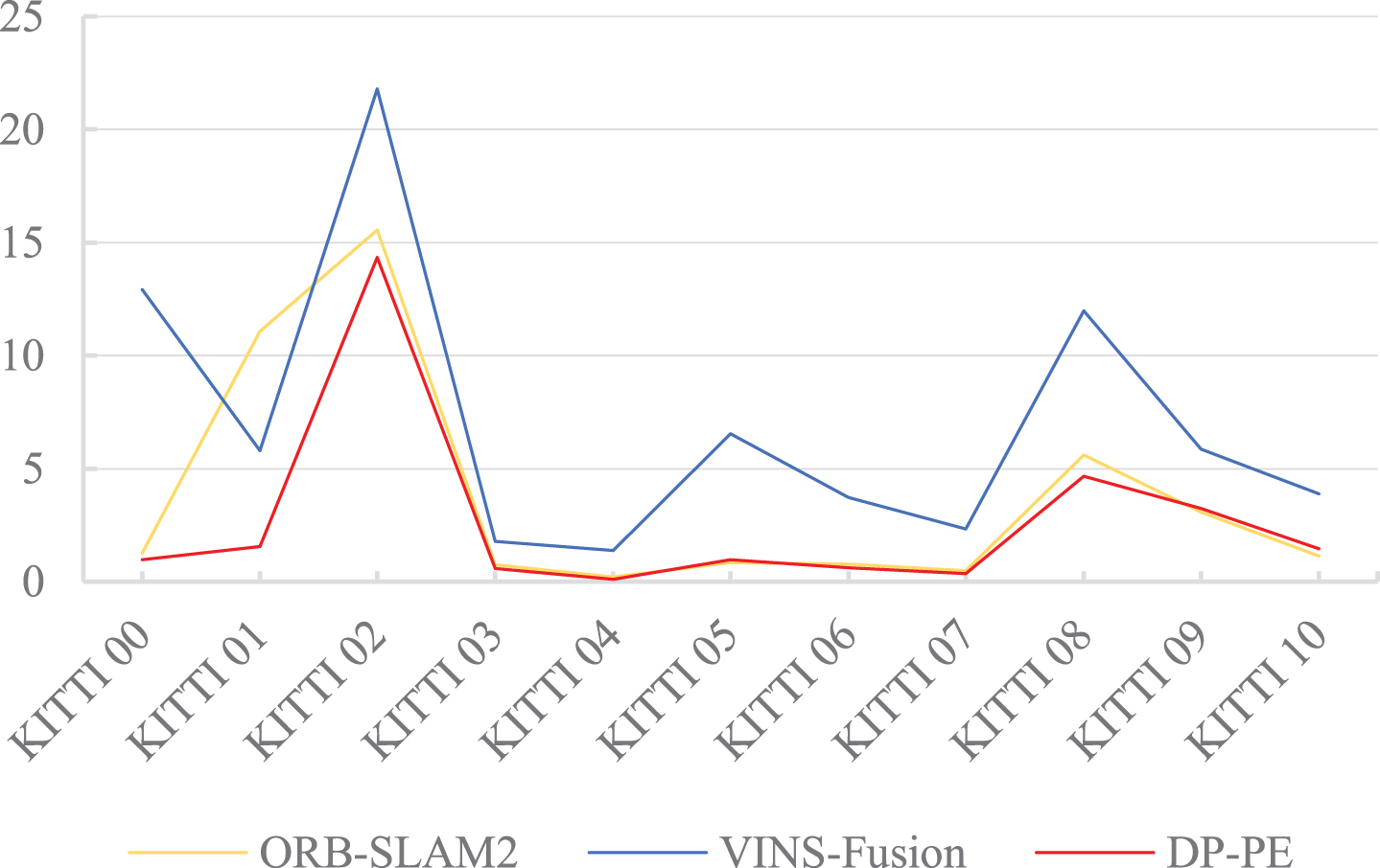
RMSE error comparison tested on KITTI 00∼10.
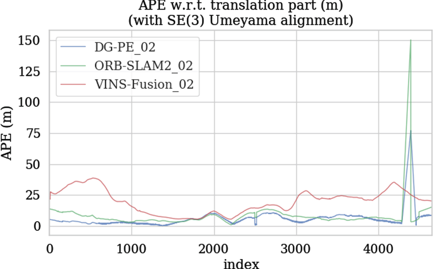
APE change curve tested on KITTI 02.

APE change curve tested on KITTI 05.
Figure 17 shows the statistics of the RMSE results of DP-PE, ORB-SLAM2 and VINS-Fusion on the KITTI 00∼10 sequence. The analysis shows that the RMSE tested on the KITTI dataset by DP-PE is mostly smaller than that of ORB-SLAM2 and VINS-Fusion. Although the RMSE obtained from the ORB-SLAM2 test on the 05, 09, and 10 sequence datasets is better than that of DP-PE, the RMSE of the DP-PE algorithm is smaller than VINS-Fusion and has a small gap with ORB-SLAM2, which still maintains high positioning accuracy. The RMSE of the 01 sequence DP-PE is significantly lower than that of ORB-SLAM2 and VINS-Fusion. The main reason may be that the 01 sequence is the highway scene with many moving vehicles, which affects the positioning accuracy of ORB-SLAM2 and VINS-Fusion. DP-PE detects dynamic vehicles through deep learning-based algorithms and eliminates dynamic feature points, eliminating the phenomenon of feature point mismatches caused by dynamic scenes, therefore, DP-PE can still keep good positioning performance under the condition of dynamic interference. KIITI 04 is an urban expressway scene with good road conditions, a small number of moving vehicles and little dynamic interference. Both DP-PE and ORB-SLAM2 have good positioning effect in the KITTI 04 sequence test. KITTI 02, 03 and 09 are urban arterial roads scene, and KITTI 00, 05, 06, 07, 08 and 10 are urban branch roads scene. In these scenes, there are either few dynamic objects (vehicles and pedestrians) or “pseudo-dynamic objects", such as stationary parked vehicles and stationary pedestrians on both sides of the road. Combined with Figs. 18, 20 and 21, it can be seen that DP-PE has a better positioning effect than ORB-SLAM2 and VINS-Fusion in these scenes. The introduction of the target detection algorithm does not reduce the positioning accuracy due to the elimination of the feature points of the stationary target, resulting in fewer feature points participating in matching and optimization. This shows the effectiveness of the DP-PE pseudo-dynamic feature point screening method.
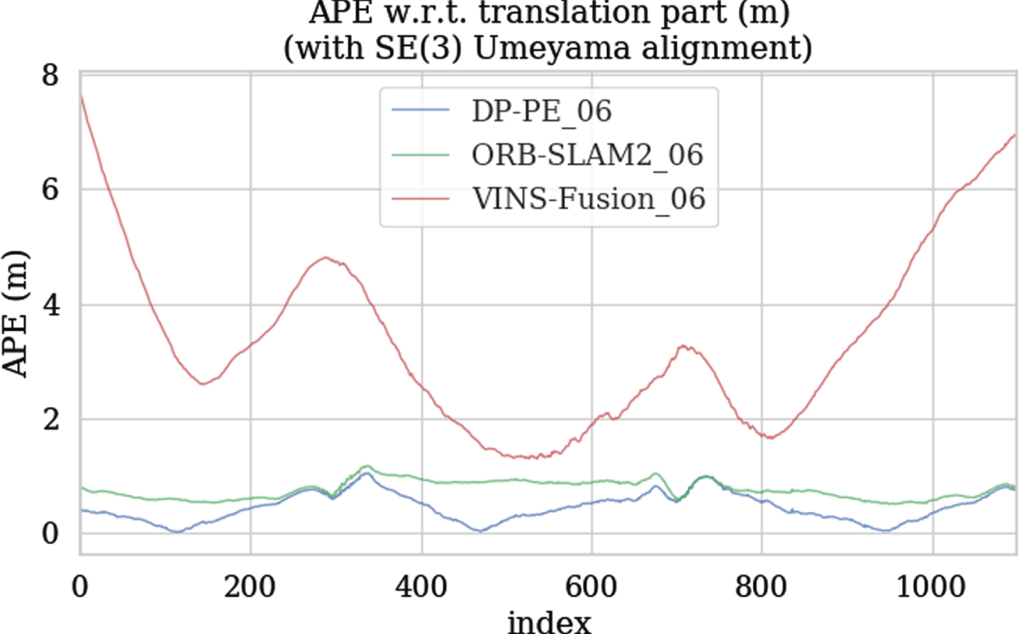
APE change curve tested on KITTI 06.
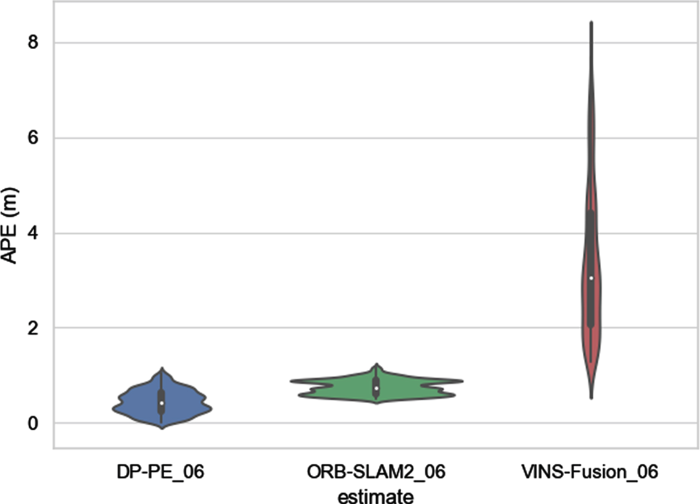
APE violin diagram tested on the KITTI 06.
(1) Acceleration experiment of ORB feature extraction and matching
Five groups of images are randomly selected from the KITTI dataset to test the acceleration effect of feature point extraction and matching. The time consumption of each group of image feature point extraction and matching is shown in Table 2. It can be seen from the table that the ORB feature point extraction and matching algorithm in this paper has been able to run efficiently on the CPU serial computing platform. For example, on an image with a resolution of 1226*370, it only takes 27.8 milliseconds to complete the detection and matching of feature points, that is, the processing frame speed is about 36 frames per second. In the CPU-GPU heterogeneous platform, the extraction and matching of feature points can be completed in single-digit time. If the ratio of CPU time to GPU time for tasks with the same computation is defined as the speedup ratio, then the average speedup ratio of ORB feature points extraction and matching under the computing framework of Section 4.2 and on the CPU serial computing platform reaches 6.5 times, and the average frame speed is 190 frames per second, which significantly improves the extraction and matching time of feature points.
Feature point extraction and matching time and speedup ratio
Feature point extraction and matching time and speedup ratio
(2) Real-time evaluation of DP-PE system
The real-time performance of the pose estimation system is mainly reflected in the computational efficiency of the tracking thread. Table 3 shows the statistical results of the time-consuming test of the DP-PE tracking thread in the KITTI dataset. As can be seen from the table, the average time consuming per frame image of DP-PE in the KITTI dataset before acceleration is 59 ms, and after acceleration, the average time consuming per frame image of DP-PE in KITTI dataset is 9.0 ms, the processing frame speed is 111 frames per second, and the average speedup ratio is 6.6.
Tracking thread time-consuming tested on KITTI
Based on the above analysis, it can be seen that the pose estimation system accelerated by the CPU-GPU heterogeneous platform has higher tracking efficiency, the average acceleration performance is improved by about 7 times, and the average frame rate is about 110 frames per second, which can meet the real-time requirements of pose estimation of intelligent vehicles.
An improved SSD algorithm based on CNN is designed to detect dynamic objects (vehicles and pedestrians) in the driving environment. Improved SSD runs in parallel with the tracking thread, passes the detected dynamic object position parameters to the tracking thread, and combines the extracted feature points with the geometric areas of dynamic objects to eliminate dynamic objects, so as to filter out static feature points and effectively reduce the influence of dynamic objects on the positioning accuracy of the system.
A screening method of “pseudo-dynamic feature points” based on the geometric characteristics of feature points is proposed. The “pseudo-dynamic feature points” are screened out and participate in the subsequent feature point matching, which further improves the robustness of the system. The test results show that in the scene with many dynamic objects, DP-PE has a significant improvement in positioning accuracy compared with ORB-SLAM2 and VINS-Fusion, which meets the positioning accuracy requirements of autonomous vehicles in dynamic scenes.
The time-consuming proportion of each part of DP-PE tracking thread is analyzed to determine the feature point extraction, matching and positioning as the modules to be optimized. We establish a parallel computing framework for feature point extraction and matching on the CPU-GPU heterogeneous platform to achieve the acceleration of this part; For the localization part, a 3D interior point detection strategy is proposed to realize the parallel search of map points, and the saturated linear kernel function is used to act on the reprojection error, so as to reduce the influence of outliers on the positioning accuracy and realize the parallel calculation of pose optimization. The experimental results show that the average speedup ratio of feature point extraction and matching is 6.5 times, and the overall computational efficiency of the system is about 7 times higher than that before acceleration, which effectively improves the efficiency of the pose estimation system of the autonomous driving vehicle.
Footnotes
Acknowledgments
This research was supported by the Science and Technology Planning Project of Guangdong Province (No.2018A030313727) and National Natural Science Foundation of China (No.51775193). This financial support is gratefully acknowledged.