
Abstract
This paper presents an Enhanced Whale Optimization Algorithm (EWO) approach for tuning to perfection of Fractional Order Proportional Integral and integral order Controller (FOPI λ) is used to sensorless speed control of permanent magnet Brushless DC (PMBLDC) motor under the operating dynamic condition such as (i) speed change by set speed command signal (ii) varying load conditions, (iii) integrated conditions and (iv) controller parameters uncertainty. On the other hand, it deals with a reduced THD (Total Harmonic Distortion) under dynamic operating conditions to improve the power quality for the above control system. Here present are three optimization techniques, namely (i) Enhanced Whale Optimization (EWO), (ii) Invasive Weed Optimization (IWO), and (iii) Social Spider Optimization (SSO) for fine-tuning of the FOPI λ controller parameters with reduction of THD. The proposed optimization algorithm optimized FOPI λ controller are compared under various BLDC motor operating conditions. Based on the results of MATLAB/Simulink models, the proposed algorithms are evaluated. Here, both the simulation and the results of the experiments are validated for the proposed controller technique. It demonstrates that the effectiveness of the proposed controllers is completely validated by comparing the three intelligent optimization techniques mentioned above. The EWO optimized FOPI λ controller for speed control of sensorless PMBLDC motor clearly outperforms the other two intelligent controllers by minimizing the time domain parameters, THD, performance Indices error, convergence time, control efforts, cost function, mean and standard deviation.
Introduction
Brushless direct current (BLDC) motors have become popular in recent years for an industrial purpose because the nominal characteristics are lightweight, high torque, compact structure, high performance, controllability, low maintenance, and better efficiency [1]. The BLDC motors are permanent magnet motors with trapezoidal/rectangular EMF waves, and position sensors are essential for proper operation. The broadcast of the BLDC is activated electronically using an inverter and a counter-counter position sensor i.e. hall sensors. The rotor position information is still very important and can usually be measured with a Hall sensor. To reliably measure the rotational speed of a BLDC motor using a signal transmitted from the built-in hall sensor, the rotor pole of the BLDC motor should be aligned with the Hall Sensor [2].
In sensorless BLDC motor, the information of rotor position is highly needed which is used for the current communication towards the stator windings [3]. Many researchers have been focused on sensorless communication for BLDC motor drives which optimally gives better performance with proper control strategies [4].
Furthermore, the FOPI λ controller is a development of the FOPID (Integer Order Proportional Integral Derivative) controller [5]. Proportional gain (Kp), Integral gain (Ki), and Integral order (λ) are the three functional DOF parameters of a standard FOPI λ controller [6]. The FOPI λ controller provides greater flexibility and better transient and steady-state characteristics. The controller control parameters to be fine-tuned in order to obtain optimal results using optimization techniques [7]. However, Conventional optimization techniques produce more computation time, tot solving non-linearity problems, longer time for settling, steady-state error fluctuation, and poor robust speed control to compute optimal results which limits system performance.
In literature, [8] presented the work related to FOPI λ controller speed control of induction motors can be fine-tuned offline. From the offline tuning results, steady-state error and settling time are maximum values due to sudden external disturbance of the system. MGA, ABC, and BA are used to tune the FOPID controller to perfection [9, 10]. MATLAB simulations based on sensorless BLDC motor drive speed step response features, 50%load, and 100%load conditions achieve MGA, ABC, and specific BA strong scheme. This analysis does not focus on changing set speed conditions and integrated conditions.
The PSO optimized PI controller for BLDC motor speed regulation is created [11]. The controller adjusts the gain parameters and the PSO algorithm’s performance optimized PI controller parameters to measure time-domain parameters. The proposed [12] PSO–GSA optimised fuzzy PI controller design for BLDC motor. The proposed algorithm PSO–GSA is used to tune controller parameters can obtain improved time-domain performance. From the results, it is noted that poor performance and more settling time. In this study [13], the WOA optimized FO fuzzy PI controller for BLDC motor speed control. From the results, the performance of the control system has been investigated at various speeds to assess its robustness.
For BLDC motors, a firefly algorithm based FOPID controller is employed to provide desired torque and speed control [14]. The reference torque is compared to the estimated torque, and the error is sent to the FOPID controller in a direct instantaneous torque control system. It controls the motor torque with reduced ripple over a wide range of speed.
Optimal coronavirus Optimization algorithm (CVOA) is used to choose the best PID controller for a BLDC motor [15]. To alter the time domain parameters, a multi objective function can be employed. The coronavirus Optimization algorithm is a well-known metaheuristic optimization techniques used to improve the dynamic performance (minimum rise time, minimum settling time and overshoot) of the BLDC motor [16].
This paper examines optimization strategies for BLDC motor speed control based on optimal tuning of the FOPI λ controller in terms of time-domain characteristics minimization. The proposed intelligent strategies improved FOPI controller is simulated in MATLAB-R2019a, M-file on a PC Intel Core i5-4200U CPU, 2.30 GHz speed system running Windows 10®.
This paper’s major contributions include: Using Enhanced Whale Optimization (EWO), Invasive Weed Optimization (IWO), and Social Spider Optimization, create a MATLAB/Simulink model of a FOPI controller for sensorless speed control of a BLDC motor (SSO). Various operating conditions for BLDC motors to be considered under (i) Changes in speed based on step response (ii) change the loading conditions, (iii) integrate the conditions, and (iv) keep the load constant. The simulation results are compared to the proposed intelligent technique EWO, IWO and SSO optimized FOPI
λ controllers for Sensorless BLDC motor speed control. The optimum controller for the above-mentioned system is validated and recommended based on the results. The FOPI
λ controller is used to generate the pulse width modulated signal used in the inverter and investigated the THD. In addition, to improve the power quality by reduction of Total Harmonics distortion for above dynamic operating conditions. Under the above operating conditions, we measured the control efforts, cost function, mean deviation, standard deviation, convergence time, performance Indices (ITAE, ISE, IAE, and RMSE), and time-domain parameters (tr, tp, ts, ess) of an EWO optimised FOPI controller for BLDC motor. In order to demonstrate the utility of the suggested controller design, an experimental model is created, validated for specific operating conditions, and the results compared to simulation results.
The article’s content organization.is shown in Fig. 1.
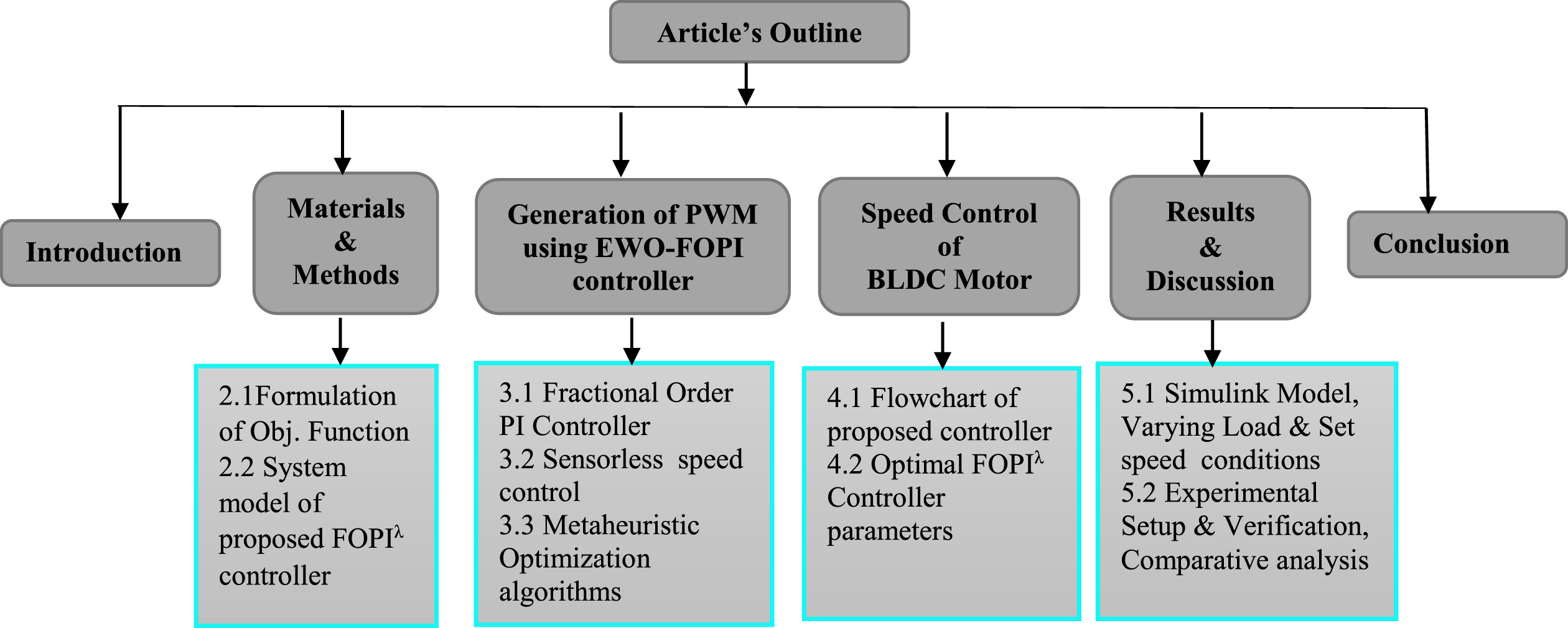
Content organization of the article.
This section emphasizes the necessity of formulation of the objective function and system model of proposed FO-PI λ controller in the present scenario of speed control systems. A briefing of sensorless speed control relevant to the proposed work is presented.
Formulation of objective functions
The cost function is a design constraint assigned to determine optimum parameters for controllers [17]. A typical mathematical cost function optimization formulation can be expressed as:
(i) Minimization of the cost function (f cost )
A cost function (f cost ) is utilised to find the best tuning settings for the FOPI λ controller under variable load and set speed (Ns) conditions of the BLDC motor.
The set speed is N(t)set, the estimated speed is N(t)est. of the BLDC motor for each sample simulation time (T) for the optimization of the FOPI
λ controller
(ii) Performance indices are minimised.
(iii) The scope of the FOPI
λ controller’s optimal tuning parameter is given in Equations (6) to (8) as,,
A FOPI λ controller creates an output signal which is a combination of three controller parameters (Kp, Ki,λ) gain values. It produces a zero-control error and is insignificant for measurement channel interference [18]. To configure the PI λ controller, the integration time must be set to zero, and the maximum aspect ratio must be specified. The FOPI λ allows for greater flexibility in the design of the BLDC motor’s speed controller. The model of fractional order PI λ controller is shown in Fig. 2.
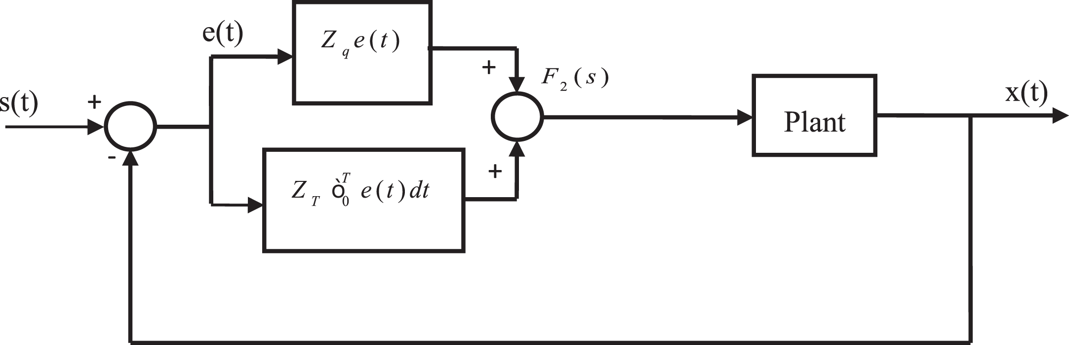
System model of Fractional Order PI λ controller.
The response can be acquired from fractional-order PI
λ controller transfer function
The phase and gain are as follows,
The open-loop response F2 (iω) is
The phase of F2 (iω) is
The following equation represents the relationship between Z
j
and λ
where
The gain is
The equation shows about Z
j
and λ
where
Then
Z
Q
can be established by
Then
The FO-PI
λ is an exceptional instance of a FOPI
λ controller that is less sensitive to controller parameter variables. The fractional order PI
λ controller offers more flexibility to configure the controller using two additional configuration options.
Where
Where x is the integer such that x - 1 < γ ≤ x.
If initial value
At the z
th
sampling time, calculate error E (z):
Where i the set is value and p (z) is the system output. Calculate PI
λ controller output:
Generation of pulse width modulated signal using optimized FOPI λ controller
The open loop transfer function of BLDC motor is given by
Therefore, FO-PI controller has been used, which is given by
The objective function is given by
By using this, reduce the objective function to control the BLDC motor’s speed to the set point state. This will help us to manage the speed of the BLDC motors. The BLDC motors’ speed can be controlled by the PID controller and thus it is efficient for the generation of width pulse modulated signal used in the inverter and the control signal used in the capacitor. Also, reduce the torque and speed control using the motor. The working function of the proposed PWM signal generation is given in Algorithm 1.
Algorithm 1- Drive control using SSO
The FOPI λ controller is a closed loop feedback signal system which is used for process control and motor speed control systems [19]. It has three parameters degrees such as proportional gain (K P ), Integral gain(K I ) & Integral order (λ). Figure 3 depicts the FOPI λ controller’s basic construction. The error detector e(t) is compared with the set point and measured variable Y(s). The purpose of FOPI controller has been optimal tuned with the help of EWO, IWO and SSO optimization algorithms in order to minimize the cost function, control effort, steady state error, settling time and performance indices.
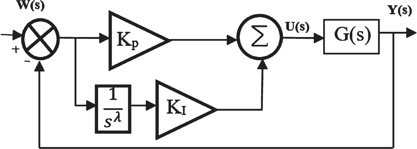
FOPI λ controller’s basic construction.
The transfer function of FOPI is
The equation for the FOPI controller in the time domain is
The closed loop control system’s unit step response using a FOPI controller is given by
From Equation (43), the transfer function of a closed loop system is expressed as,
Laplace inversion of Equation (43) yields the unit step response G closed (t).
The permanent magnet BLDC motors are controlled electronically, it requires the rotor position information to achieve suitable commutation of current in the stator winding. For rotor position information, hall sensors are being used [20]. But the use of hall sensors is not desirable because it increases the cost, complexity in structure and also the sensor fails at high-temperature applications. Sensorless BLDC motor control is also known as sensorless trapezoidal BLDC motor control. Back EMF refers to the voltage that is proportional to the BLDC motor speed. Back EMF can be used to calculate flux, torque, and the rotor speed and position of a motor. The sensorless BLDC motor speed control is shown in Fig. 4.
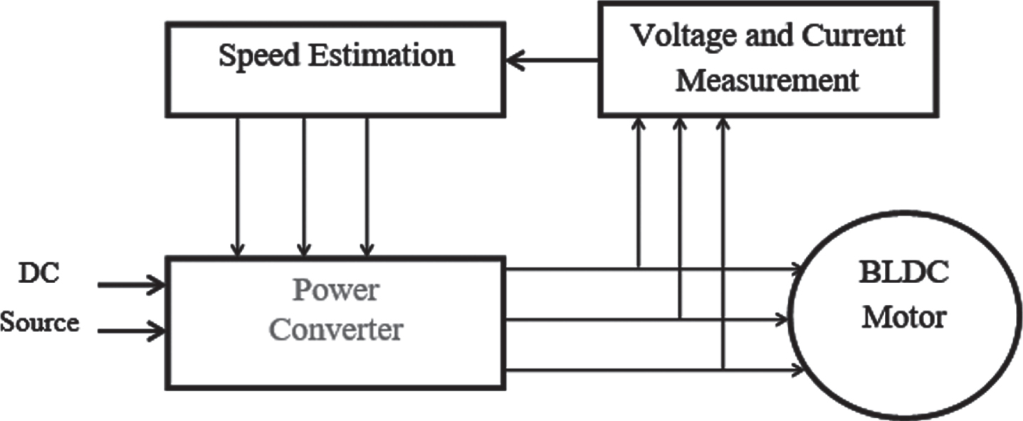
Sensorless BLDC motor speed control.
Social spider optimization (SSO)
Cuevas et al. proposed the social spider optimization (SSO) algorithm [21]. This is a swarm-based technique that takes into account the social intelligence of the colony’s spiders. [22]. The main motivation for this method is the social interaction of spiders using web vibrations. In the same way, search optimization problems are treated as a spider web and a search optimal colony [23]. The Equation (44) shows the mathematic equation of vibration of spider
It is the status of the search agents that determines the operator for gender. Female updates the position as follows:
For ND-type spiders:
For D-type spiders:
Except for female movements, these Equations (46) reveal that ND-type spiders can only move females and cannot go backward. The mating distance can be more than one male and one female. Therefore, the roulette wheel algorithm selects parents according to their fitness values. The new spider has a combination of male genes (variables). If a new spider is more suitable than another spider, the unsuitable spider will be removed and added to the population.
Invasive weed optimization (IWO) is a one-of-a-kind numerical stochastic optimization algorithm that was inspired by current weed invasion [24]. Weeds are a major threat to healthy plants and actively growing fruit crops. It is highly resistant and adaptable to environmental changes [25]. This algorithm reflects the resistance, adaptability, and incompatibility of the model community. This method is extremely simple, but it is useful for combining relevant solutions with key features such as weed colonization, growth, and competition. [26].
The following is the definition of this map:
Algorithm 2 - Drive control system using invasive weed optimization
In which i
th
iteration is the new weed position
For sensorless speed control of BLDC motors, the Enhanced Whale Optimization [28] is used to optimise the FOPI controller parameter to achieve design constraints (i) settling time≤1 sec (ii) steady-state error (e
ss
)≤1 1%. The conventional Whale Optimization Algorithm (WOA) is affected search space, convergence problems and updated its position issues. To overcome the above problems of the WOA, the enhanced method Lévy flight strategy [29] is used in WOA with the enhanced mutation operator based on ranking are presented into the WOA. The improved whale optimization method can identify the global best solution by balancing exploration and exploitation.
Algorithm 3- Drive control system using advanced whale optimization
This sector focused proposed EWO optimized Sensorless BLDC motor speed control with the FOPI λ controller. An inverter is a static equipment that produces AC voltage from DC-DC boost converter voltage by triggering the power devices. The switching timing is determined by the switching logic. The voltage and current values are measured in the sensorless technique, and the rotor speed is approximated by using the Kalman filter algorithm. The Kalman Filter (KF) method is used to estimate the motor speed [30]. The following factors must be considered when estimating the motor speed are (i) A linear machine’s dynamic state model (ii) Model selection for the machine and (iii) The system gradient and measurement matrices are calculated. The voltage and current on the stator winding line are used to do the calculation. The linear system’s state-space model in the digital domain. Figure 5 shows the WOA- FOPI λ controller functional blocks for BLDC motor.
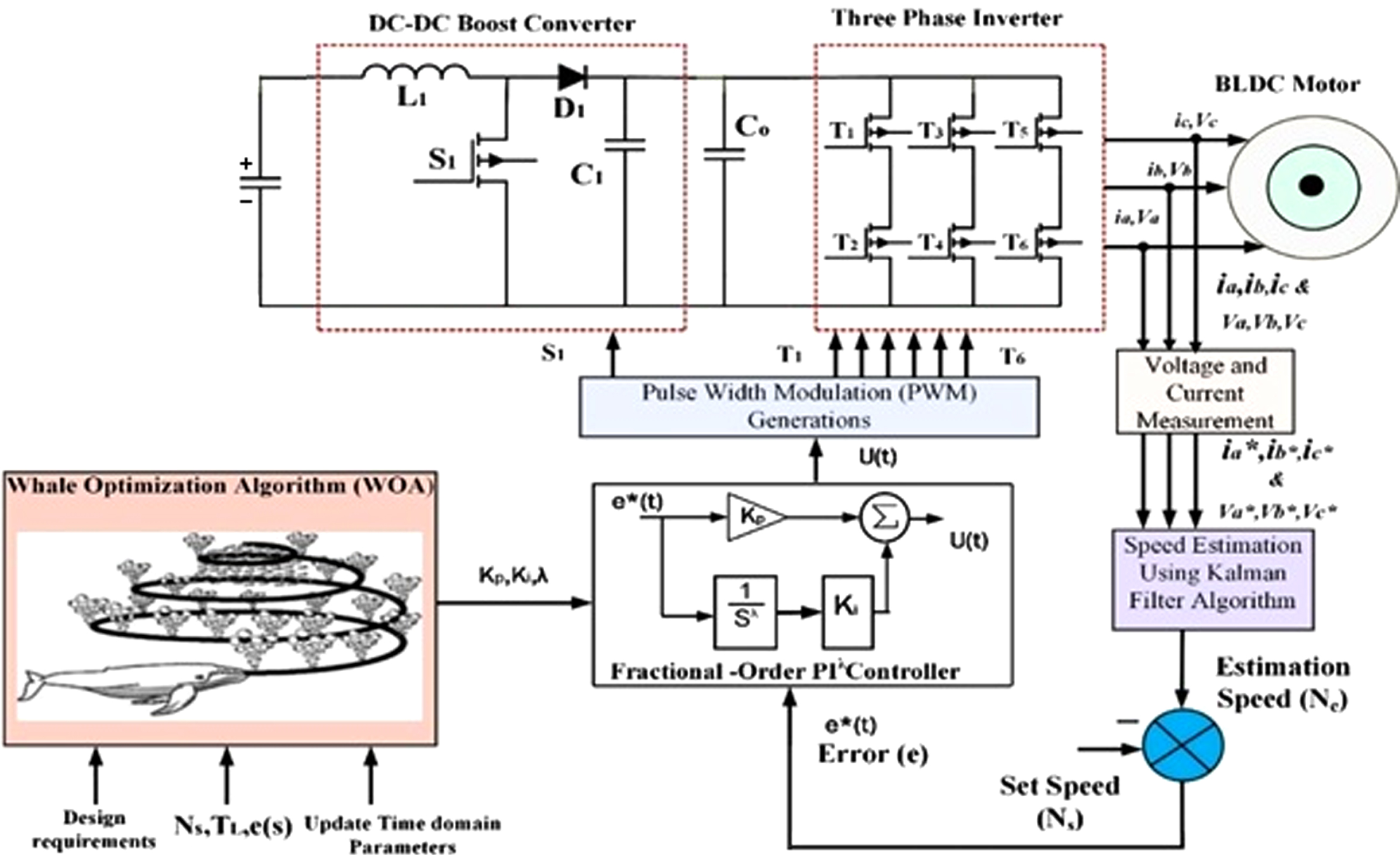
WOA- FOPI λ controller functional blocks for BLDC motor.
The speed estimation is achieved with the help of voltage and current. The error detector receives the estimated speed in rpm (Ne) and manually sets the reference speed i.e. set speed to 1500 rpm (Ns). The error detector generates a difference value that is send to the FOPI λ controller. The controller produces the required tuning parameters Kp, Ki, λ with the help of proposed intelligent techniques namely WOA. The switching logic circuits receive the control signal u(t) from the FOPI λ controller. The switching logic circuits generate the switching sequence to energize the stator winding. The PWM signal is generated by a pulse generator for controlling the voltage with the aid of a varying firing angle. The motor speed is controlled by varying the voltage, which activates the semiconductor switches in the PWM inverter.
The steps for obtaining the FOPI λ controller parameters (Kp, Ki, and λ) can be depicted in a flow chart. Recognize the suggested EWO-FOPI controller for BLDC motor’s design constraint as Equations (58 & 59) and use the proposed EWO algorithm to acquire the initial FOPI λ controller parameters Kp, Ki, Kd, λ, Figure 6 depicts the flowchart of an upgraded genetic algorithm-based FO PI λ controller for sensorless BLDC motor drive.
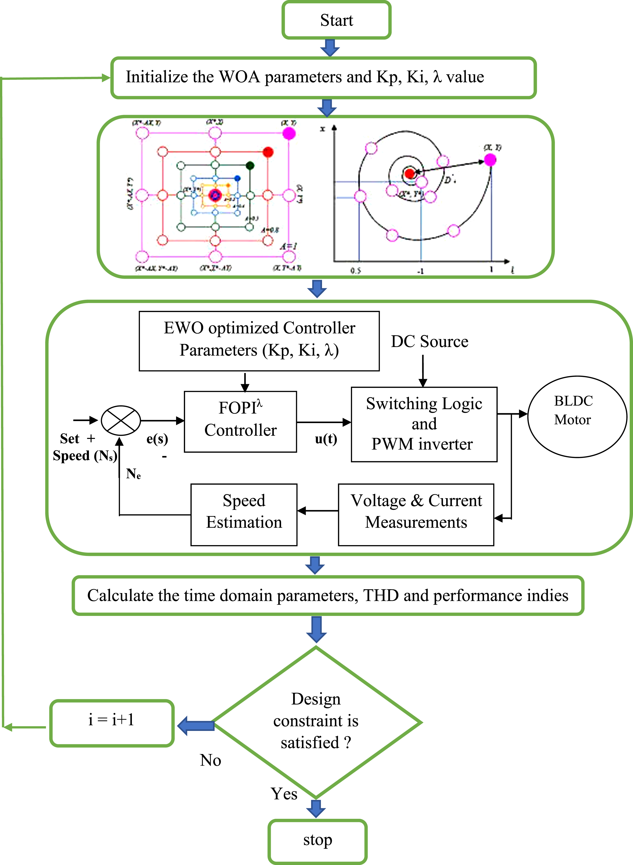
Flowchart of proposed EWO-FO PI λ controller.
The following design constraint is considered Reduction of settling time (t
s
)
Reduction of steady-state error (e
ss
)
A minimum steady-state error is required since the system’s ultimate value should approach the reference input.
The key parameters are the cost function’s minimal value and the control effort to decide the EWO optimized FOPI λ controller to be better than SSO and IWO. The optimal FOPI λ controller parameters, cost function, and control effort for sensorless BLDC motor are shown in Table 1.
Controller parameters of varying load conditions
Controller parameters of varying load conditions
Table 2 shows the controller parameters, cost function, and control effort values for varying set speed conditions. To validate the competence of the SSO, IWO and EWO optimized the Sensorless BLDC motor speed control with the FOPI controller by various tests, the controller parameters value, Cost function (J), and control effort are measured. Table 3 shows the values for integrated conditions controller settings, cost function, and control effort. Here varying set speed condition are analyzed for different tests are described below:
Variable set speed conditions with controller parameters
Controller parameters for integrated conditions
Test 1 - Change the speed - 500 rpm to 1500 rpm.
Test 2 - Change the speed - 1000 rpm to 1500 rpm.
Test 3 - Change the speed - 1500 rpm to 1000 rpm.
Test 4 - Change the speed - 1500 rpm to 500 rpm.
Test 5 - Change the speed - 1000 rpm to 500 rpm.
The MATLAB simulation results are presented to demonstrate the performance of the EWO optimised FOPI λ controller for sensorless BLDC motor speed response under various operating conditions.
Simulation setup and results
This section evaluates the proposed performance of the sensorless BLDC motor using SSO, IWO and EWO optimized FOPI λ controller by simulation platform. The optimization techniques are utilised to fine-tune the FOPI λ controller for BLDC motor speed control under various working conditions. The proposed optimization techniques based on FOPI λ controllers are implemented in Windows 10® using a MATLAB 2020a M file. The suggested EWO-FOPI λ controller design is compared to the IWO- FOPI λ and SSO- FOPI λ controller methods for performance. The parameters of optimization algorithms are shown in Table 4.
Parameters of Optimization Algorithms
Parameters of Optimization Algorithms
The EWO controller, as compared to the other two intelligent controllers, reduces the magnitude of stator current. Here, magnitude of stator current is 13 amps at the time of starting of BLDC motor. The EWO optimized FOPI λ controller can decrease the energized time of stator winding. It is observed that the stator back EMF is better time-domain characteristics by EWO optimized FOPI λ controller. For a proposed controller, the stator current and back EMF of a BLDC motor is shown in Figs. 7 8.

Stator current of BLDC motor for proposed controllers.

Back EMF of BLDC motor for a proposed controller.
It has been demonstrated that different load situations, such as 10%load, 30%load, 50%load, 70%load, and 90%load condition. The EWO optimised FOPI λ controller for sensorless BLDC motor speed control is more effective, according to the results. It depicts the settling time of the proposed EWO- FOPI λ controller is very low in terms of 3%, 8%, 7%for SSO and IWO techniques respectively. The proposed EWO- FOPI λ controller has a very low steady-state error (rpm) in terms of 25%, 3%, and 10%for SSO, and IWO techniques respectively. Figure 9 shows the optimization-based FOPI λ controller for varying load conditions.

BLDC motor speed response under conditions of varying load.
The proposed FOPI λ controller’s rise time is very low compared to FOPI λ controller in terms of 9%, 28%, 33%for SSO, IWO, and IWO techniques respectively. The peak time of the proposed FOPI λ controller is very low compared to FOPI λ controller in terms of 7%, 19%, and 16%for SSO, IWO, and EWO techniques respectively. It depicts the Settling time of the proposed FO-PI controller is very low compared to the FO-PI controller in terms of 9.3%, 12.5%, and 9.3%for SSO, IWO, and IWO respectively. In comparison to the FO-PI controller, the proposed FO-PI controller has a very low steady-state error in terms of the 7%, 13.3%, and 20%for SSO, IWO, and EWO respectively. The performance in time domain under varying load conditions is shown in Table 5.
Performance in time domain under varying load conditions
The optimization techniques based on BLDC Motor speed response under Test 1 conditions are indicated in Fig. 10. In terms of peak time, the suggested FO-PI controller has a much shorter peak time than the FOPI λ controller in terms of the 8%, 5%, and 4%for SSO, IWO, and EWO respectively. The proposed FOPI λ controller has a very low steady-state error (rpm) when compared to the FOPI λ controller in terms of the 22.5%, 20%, and 17.5%for SSO, IWO, and EWO respectively. The suggested FOPI λ controller has a much lower steady-state error (rpm) than the FOPI λ controller in terms of the 8%, 5%, and 3%for SSO, IWO, and EWO respectively. Performance in time domain under varying set speed conditions is shown in Table 6.

Optimization techniques based BLDC Motor speed response under Test 1 conditions.
Performance in time domain under varying set speed conditions
The optimization techniques-based BLDC Motor speed response under Test 4 conditions is shown in Fig. 11. Reduce the proposed FOPI controller’s settling time value is higher compared to FOPI λ controller in terms of the 0.8%, 0.5%, and 0.3%for SSO, IWO, and EWO respectively. When compared to the FOPI λ controller, the proposed FOPI controller has a higher peak time value in terms of 4.5%, 3%, and 2 %for SSO, IWO and EWO respectively. The steady-state error of the proposed FOPI λ controller is very low compared to the FOPI λ controller in terms of the 5%, 12%, and 25%for SSO, IWO, and EWO respectively. The performance in time domain under integrated conditions (Case A and varying load) is shown in Table 7.
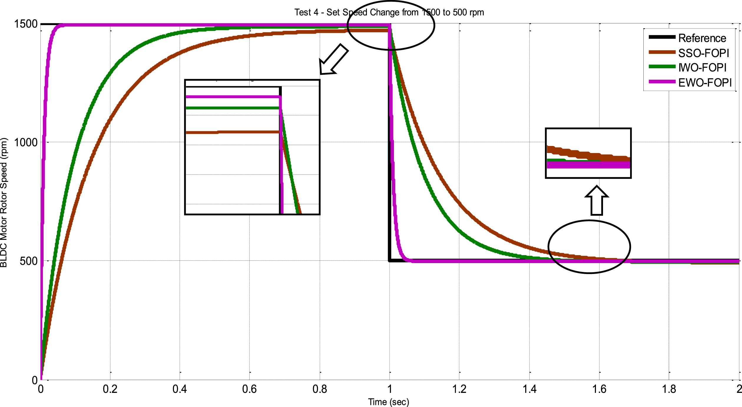
optimization techniques based BLDC Motor speed response under Test 4 conditions.
Performance in Time domain under integrated conditions (Case A and varying load)
From these above results, the EWO optimized FOPI λ controller has a minimal output characteristic value, indicating superiority over SSO and IWO optimized FOPI λ controller for the BLDC motor’s various operating conditions. The comparison of different optimization methods for the FOPI λ controller for sensorless speed regulation of BLDC motor drives for fine-tuning FOPI λ controller under various optimization techniques observed that the time-domain characteristics, i.e. peak time, rise time, settling time, peak overshoot and steady-state error are minimised.
The experimental setup shows the sensorless speed control of BLDC motor by EWO optimized FOPI λ controller. It is made up of an autotransformer, TMS 320–DSP kit, power converter, BLDC motor with mechanical loading arrangements, electrical parameters measuring instruments, and power quality analyzer for THD measurements. The DSP kit interface between BLDC motor and power quality analyzer. Figure 12 shows the Measurement of Total Harmonics Distortion (THD) for BLDC motor load with the EWO-FOPI λ controller.
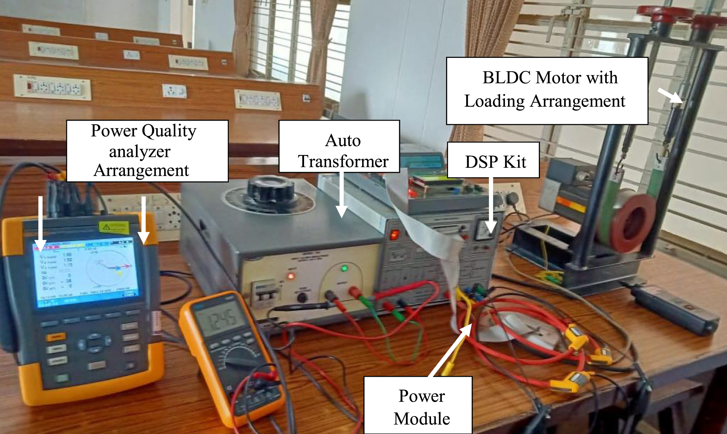
A snapshot of the hardware setup in real time.
The proposed controller’s major impact is to minimise the settling time, steady-state error of the BLDC motor, and harmonics of the inverter. The intelligent controller’s performance is evaluated and compared to the simulation results. Figures 13 (a&b) shows the measurement of phasor unbalance, voltage waveform, voltage fluctuation, and Total Harmonics Distortion (THD) for the EWO-FOPI λ controller-based BLDC motor.
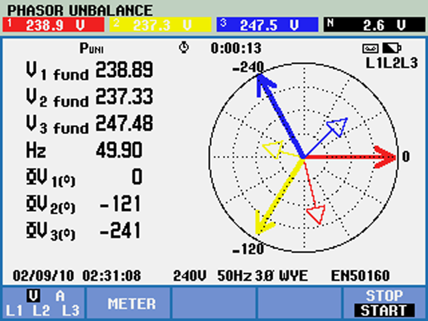
Phasor for EWO-FOPI λ controller.

Voltage waveform for EWO-FOPI λ controller.
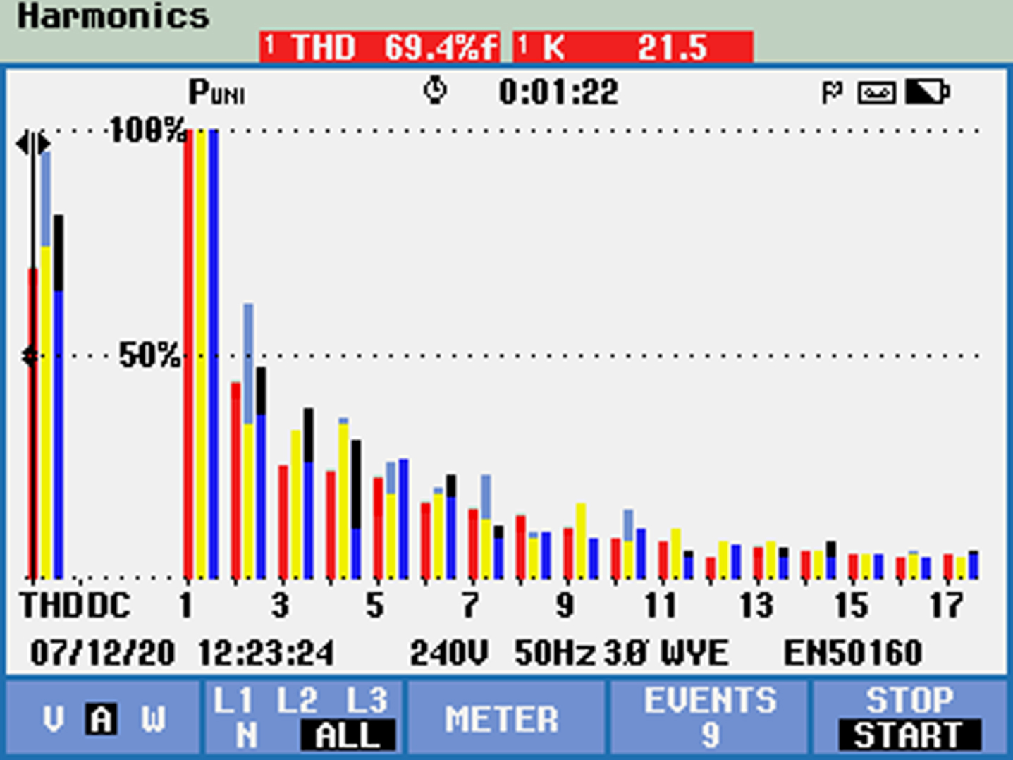
THD for EWO-FOPI λ controller.

Voltage fluctuations for EWO-FOPI λ controller.
The comparison of experiment and simulation results for the BLDC motor is shown in Table 8. From this result, the proposed EWO optimized FOPI λ controller gives the control signal tracks the speed accurately with less settling time and very small steady-state error. The comparison of simulation and experimental results of changing speed conditions is shown in Table 9. The Experimental speed response performance parameters such as rise time, peak time, settling time, and steady-state error are close to the performance parameters of simulation results.
Comparison of Simulation and Experimental results for BLDC motor
Comparison of Simulation and Experimental results of varying speed conditions
The sensorless speed control of FOPI λ controller using the proposed optimization technique in a BLDC motor is presented. The proposed three optimization techniques such as Social Spider Optimization (SSO), Invasive Weed Optimization (IWO), and Enhanced Whale Optimization (EWO) are used to create the signal with a pulse width modulation used in the inverter and the control signal. The simulation results show that the proposed EWO optimised FOPI controller is effectiveover the SSO-FOPI λ and IWO-FOPI λ controller.
Under varying load conditions, the settling time of the proposed EWO-FOPI λ controller is very low when compared to other FOPI λ controllers in terms of 8%, 7%, and 3%for SSO, IWO, and EWO techniques respectively. The steady-state error of the proposed EWO- FOPI λ controller is very low compared to the existing FO-PI λ controller in terms of 12%, 8%, and 5%for SSO, IWO, and EWO techniques respectively.
Under varying set speed conditions, the settling time of the proposed FO-PI controller is very low compared to the existing FO–PI λ controller in terms of 12.3%, 9.5%, and 6.3%for SSO, IWO, and EWO respectively. The steady-state error of the proposed EWO-FOPI λ controller is very low compared to other FOPI λ controllers in terms of the 7%, 13.3%, and 20%for SSO, IWO, and IWO respectively.
Under integrated conditions, the settling time of the proposed EWO-FOPI λ controller is very low compared to other FO–PI λ controllers in terms of 14%, 10.2%, and 7.5%for SSO, IWO, and EWO respectively. The steady-state error of the proposed FO-PI λ controller is very low compared to the FO-PI λ controller in terms of the 11%, 7%, and 5.2%for SSO, IWO, and EWO respectively.
According to the simulation results, the EWO-based FOPI λ controller outperforms the IWO and SSO. Under the above operating conditions, the sensorless speed control of a BLDC motor was optimised in terms of cost function minimization (J), controller energy, mean, standard deviation, performance indices (ITAE, ISE, IAE, RMSE), and improved time domain parameters (tr, tp, ts).