
Abstract
This paper proposes adaptive fuzzy lead-lag controller structures for power system stabilizer and flexible AC transmission system based damping controllers to increase the stability of power system. The parameters of the proposed controller are tuned by a modified grasshopper optimization algorithm (MGOA). The new algorithm named MGOA accomplishes a proper balance between exploration and exploitation phases of original grasshopper optimization algorithm. This capability of MGOA is certified by using the benchmark functions by comparing with that of a grasshopper optimization algorithm, genetic algorithm, evolutionary strategies, particle swarm optimization, bat algorithm, population based incremental learning, flower pollination algorithm, monarch butterfly optimization and improved monarch butterfly optimization. The proposed controller is optimized and verified under various loading circumstances using MGOA method. The results of MGOA are compared with grasshopper optimization algorithm, genetic algorithm, and particle swarm optimization. Additionally, the results of the proposed MGOA are compared with conventional lead-lag controller to demonstrate its superiority.
Keywords
List of Nomenclature:
Power System Stabilizer Flexible AC Transmission system Static VAR compensator Static synchronous series compensator Thyristor controlled series compensator Unified power flow controller Genetic algorithm Oppositional cuckoo algorithm Simulated annealing Particle swarm optimization Tabu search Differential evolution Bacteria foraging algorithm Battery energy storage system Grasshopper optimization algorithm Self-adaptive learning bat algorithm Lozi map-based chaotic optimizationalgorithm Hydraulic turbine and Governor Ant colony optimization Flower pollination algorithm Gravitational search algorithm State of Matter Search Firefly Algorithm Evolutionary strategies population based incremental learning monarch butterfly optimization Bat algorithm Seeker optimization algorithm Biogeography-based optimization Maximum power point tracking Single machine infinite bus Fuzzy logic controller Membership function Integral time absolute error Integral of squared error Integral time squared error Super conducting magnetic energy storage systems.
Introduction
Low-frequency oscillations are observed after disturbances in large power systems interconnected by weak tie lines. Under such circumstances, lack of an adequate system damping may result in sustained oscillations and in turn lead to separation of the system [1, 2]. In order to handle this issue, PSS is extensively favored by utilities. However, PSSs may not solely help to provide sufficient damping. Therefore, effective alternatives are necessary along with PSS. In this regard, recently developed FACTS devices can be used to provide the required damping. SSSC is an effective series FACTS controller which provides control of power flow in transmission and hence can be used to provide additional damping [3].
Literature review
Various optimization-based approaches for damping controller design such as PSO [4, 5], GA [6, 7], DE [8], OCA [9], SA [10], TS [11], BFA [12] and hybrid PSO [13] are well-established in the literature. The interaction between PSSs and SSSC-based controllers may improve or degrade the system damping. To improve overall system performance PSS and SSSC based controllers should be coordinately designed. In literature, PSS is coordinately designed with other controllers such as PSS and SSSC by GA [14], PSS and SVC by GA [15], PSS and SSSC by hybrid PSO GSA [16], PSS and TCSC [17–19] by using different techniques. It is observed from the literature that in the majority of cases lead-lag structured controllers are employed as a structure of damping controllers. The author investigates the coordinated design of fuzzy based STATCOM along with PSS using SALBA algorithm [20]. In [21], a modified SCA is used for the coordinated design of SSSC and PSS to enhance the stability of power system. The SOA technique is discussed in [22] to regulate the parameters of the coordinated structure of PSS and static synchronous compensator. In [23], the author investigates the improved version of LCOA technique for the coordinated design of SSSC controller with PSS. The modified WOA technique is discussed in [24] for the coordinated design of SSSC and PSS. The author discussed the simultaneous tuning of SSSC and PSS using BBO technique in [25]. In [26], the author discussed coordinated design of SSSC and PSS using ACO technique. The firefly algorithm is discussed in [27] to tune the parameters of PSS and SSSC controller. Recently, fuzzy-based controllers are proposed by researchers as the controllers have the ability to operate by means of imprecise inputs and the capability to cope with nonlinearity. The author investigates the Fuzzy based PSS and Fuzzy neural based SSSC controller using pattern search algorithm in [28]. In [29], an improved strategy named PSO-Based Fuzzy approach has been proposed for parameter setting and placement of UPFC based controller. A fuzzy logic-based hybrid method proposed in [30] damp out the oscillations using UPFC and PSS controllers.
Research gap and motivation
It is evident from the literature survey that though many optimization techniques solve different problems, no single meta-heuristic method is suitable for all types of problems. Hence the development of a novel and modified technique necessitates research attention. Saremi et al. recently introduced GOA [31], a new nature-inspired optimization technique. It is clear from [31] that the GOA technique outperforms other methods such as PSO, GSA, BA, FPA, SMS, FA, and GA. The performance of the original GOA is highly dependent on the appropriate selection of coefficient ‘c’ to choose the zones of attraction, repulsion, and comfort. This parameter is linearly decreased from 1 to 0.00001 in the original GOA. In this paper, a modified version of GOA (MGOA) is developed, in which the parameter ‘c’ is changed to increase the algorithm’s performance. On this note, this paper applies the MGOA technique for the design of an adaptive fuzzy lead-lag structured FACTS controller with a PSS-based controller.
Contribution and paper organization
The following objectives are carried out in the present study: To propose a modified version of GOA technique and evaluate the performance of proposed MGOA with original GOA, GA, PSO, PBIL, ES, FPA, BA, MBO and IMBO techniques using benchmark test functions. Further, optimum parameter tuning of the proposed adaptive fuzzy lead-lag structured controller is accomplished using modified GOA to dampen the oscillations. At last, the results of the above-mentioned proposed controller confirm its superiority in contrast with lead-lag structured controller for both SMIB and multi-machine power system.
The rest of this paper is organized as follows. Section 2 describes the GOA and its modification. Section 3 introduces the application of Meta-heuristic algorithms for solving real engineering problem. Section 4 describes the proposed approach. Section 5 presents the results and discussion. At last, Section 6 presents the conclusions.
GOA method and its modification
The optimization problem with local optimal avoidance and derivative-free mechanism inspired from nature, have recently been popular due to their simplicity. These optimization algorithms work in two stages named as exploration and exploitation [32]. Exploration refers to the algorithm’s tendency for highly stochastic performance during drastically varying outcomes. These large varying solutions tend to a greater exploration of the search space and the subsequent discovery of suitable locations. However, because an algorithm is designed to exploit small-scale changes, solutions are more likely to search locally. A proper balance between these two stages in optimization problem leads the solution towards the global optimum point.
Grasshopper optimization algorithm
Saremi et al. recently introduced GOA [31], based on the social behavior of the grasshopper during searching for food. The life cycle of grasshoppers is illustrated in Fig. 1. While looking for food, grasshoppers engage in exploration and exploitation actions. As a result, we can create a mathematical model based on grasshopper behavior.
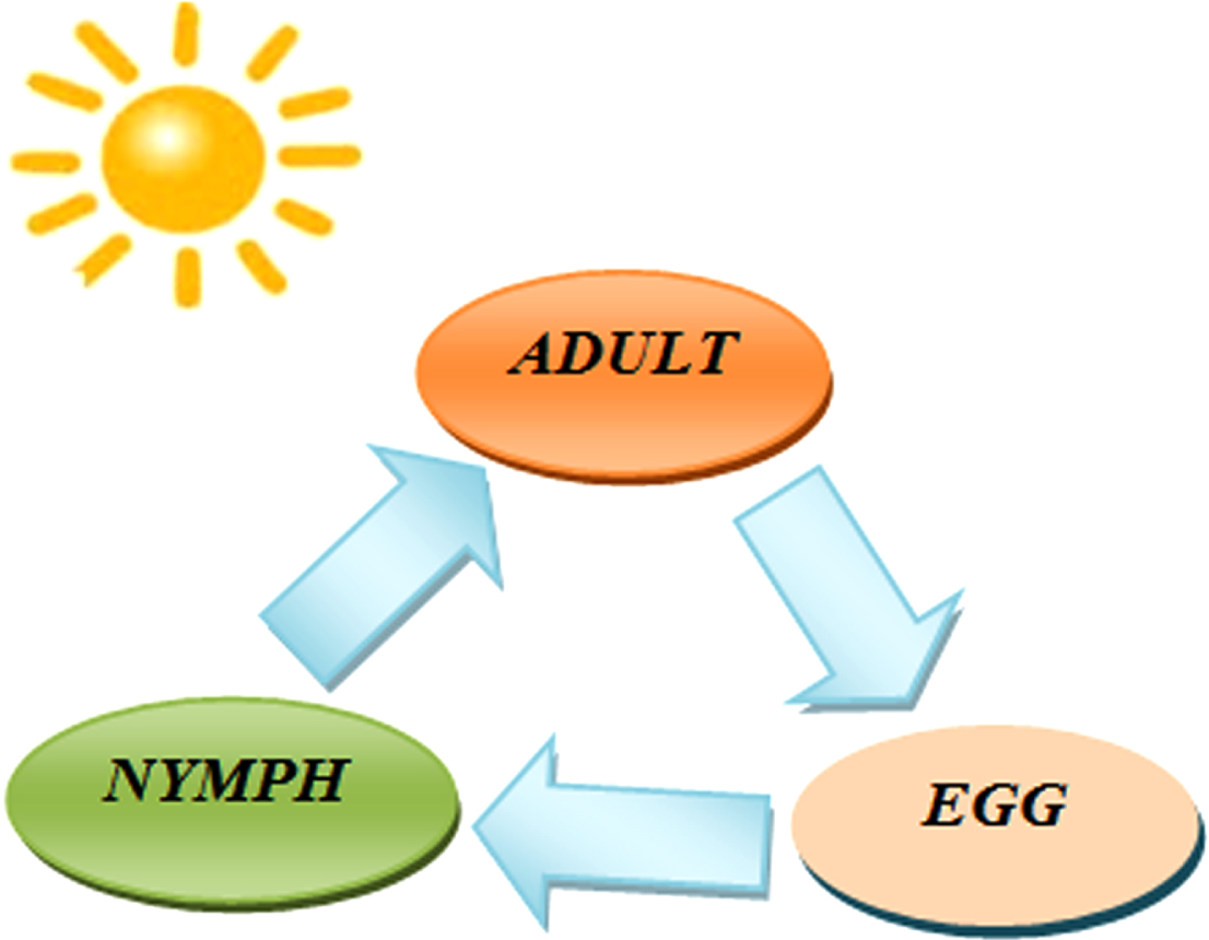
Grasshopper’s life cycle.
The following is the mathematical model for grasshopper swarming behavior that has been proposed.
Where, X j denotes the position of j-th grasshopper whose social interaction function is denoted by S i , F i denotes the force due to gravity of nth grasshopper and W i represents wind advection. It can be noted that to provide highly randomized behavior the above condition can be composed as X i = r1I i + r2F i + r3W i where r1, r2 and r3 are highly randomized value in [0,1].
The s function in (2) is estimated as
The impacts on grasshoppers’ communal interface are represented by this function s, which has a range of 0 to 15 [31]. In the meanwhile, the repulsion occurs [0 2.079]. There is neither attraction nor repulsion when the two grasshoppers are 2.079 units away from each other. It is called as the comfort zone. The attraction increases steadily when the distance lies in 2.079 to 4 units, and start decreasing gradually when reaches above 4 units. With the changes in the parameters i and a in Equation (3), artificial grasshoppers exhibit a variety of social behaviors. Figure 2 shows the social interaction of grasshoppers and zone of comfort using the functions.
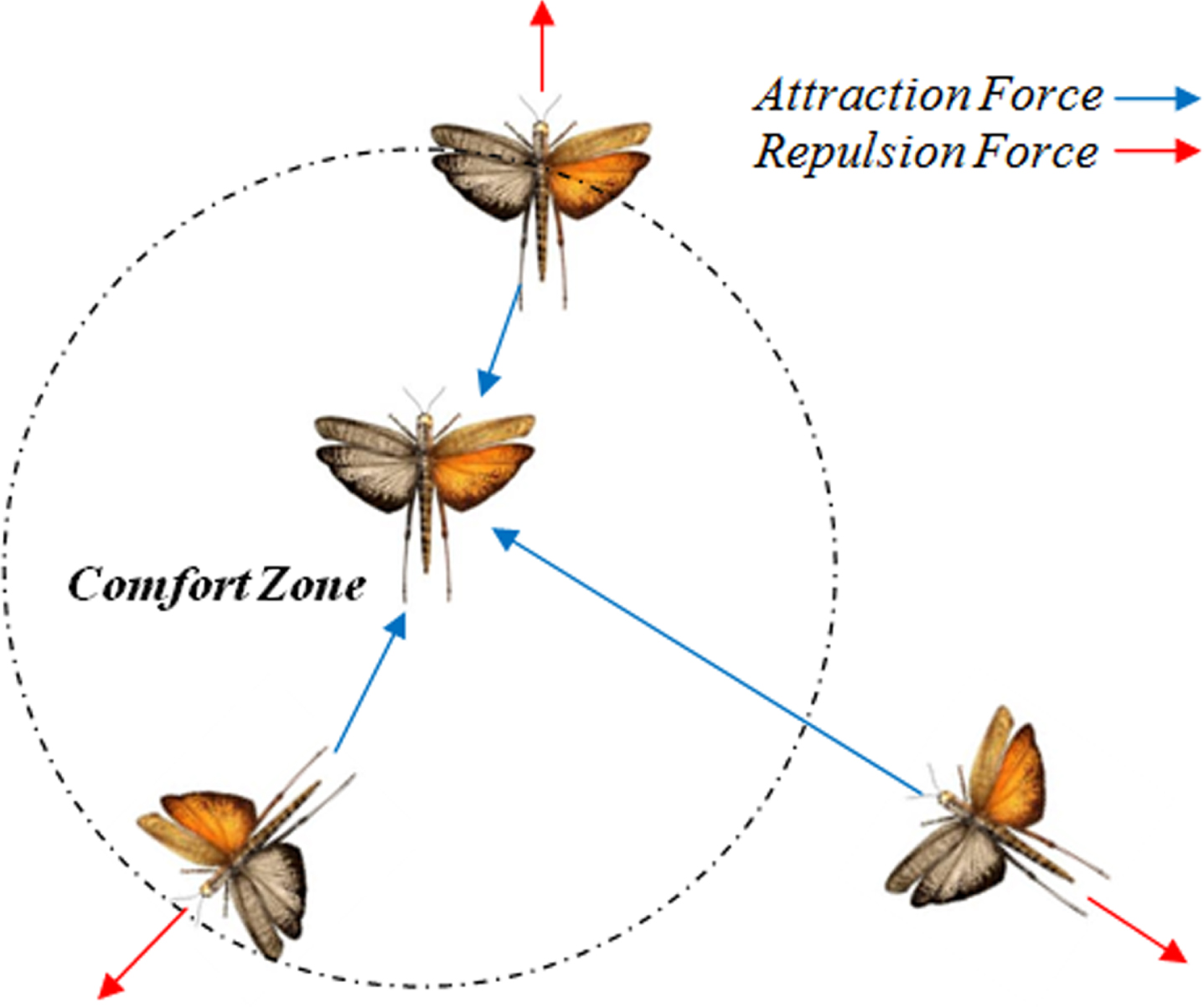
Social interaction of grasshoppers in a swarm to update their position.
Although the function S in (3) can identify the space between two grasshoppers in an area of attraction, an area of repulsion and a comfort zone, however it fails with distances greater than 10. Therefore, function S unable to identify the forces between two grasshoppers with larger distance between them. The solution to this problem is discussed in [1, 4] and a force function is defined as
The term W
i
of Equation (1) is approximated as
where u represents drift constant and
Because grasshoppers do not have wings in their nymph stage, their movement is mostly influenced by wind direction. This equation can be constructed as by inserting the S, F and W in Equation (1).
where N is the number of grasshoppers.
Since they land on the ground, the location of nymph grasshoppers must not fall below the threshold value. Therefore Equation (6) is used and the interaction among the grasshoppers in a swarm is simulated. In GOA, a modified variation of the aforementioned equation is used to solve optimization issues, as shown below.
Where, ub
d
and lb
d
is the upper limit and lower limit of the dimension d. The term
The term c in Equation (7) accounts for the delay in approaching towards the food and also in taking it. Both components of Equation (7) are multiplied with certain random variables to count the randomness in grasshopper interactions. Mathematical formulas are used to exploit and explore the search space. Because grasshoppers do not have wings, they look for food locally while they are nymphs. In adulthood they explore an extensive search space region. The primary priority in this strategy, like in stochastic optimization, is to locate a promising search space. That resulted in exploration stage. Following exploration, the grasshopper uses exploitation to search food in local areas to obtain the best global value. The behavior of the grasshopper has been considerably influenced by c as the number of iterations increases. During operation higher value of ‘c’ resulted in reduction of the search space, whereas lower value of ‘c’ reduces the attraction or repulsion forces.
The decreasing coefficient c in Equation (8) can be determined as
where c m and c n represent the highest and lowest values, I represents the current iteration, and L represents the highest number of iterations. The values of c m and c n in the original GOA algorithm are 1 and 0.00001, respectively.
The coefficient ‘c’ in Equation (7) in GOA has a significant impact on the algorithm’s convergence properties. The smaller the value of c, the slower the convergence towards the target. As a result, the algorithm will aim to avoid becoming stuck in a local optimum, improving the likelihood of obtaining the global optimal value. The value of ‘c’ in the original GOA decreases linearly from 1 to 0.00001, whereas the coefficient c in the suggested algorithm decreases from 1 to 0.00001 in such a way that it decreases gradually at the beginning and fast towards the end of the iteration. This method’s exploration potential will be enhanced due to the slow variation in c value. The variation of parameter ‘c’ is displayed in Fig. 3.
In MGOA, a correction factor of 1.5 is used to calculate the current iteration (I) and the maximum number of iterations (L), which is achieved through a series of trial runs. As a result, Equation (8) is revised as shown in Equation (9).
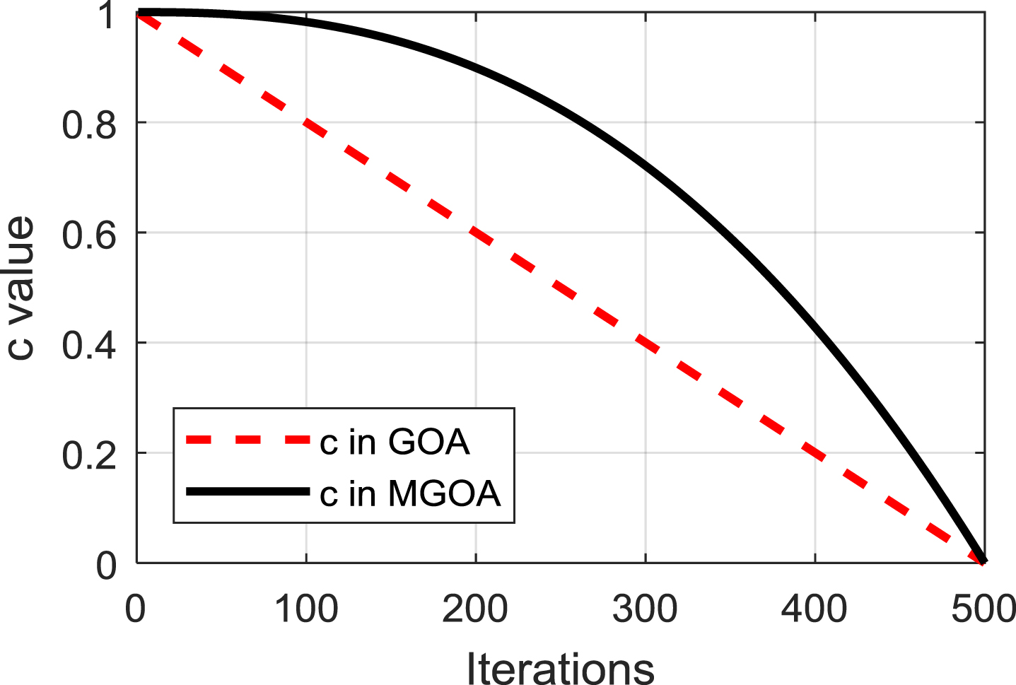
Decreasing coefficient variation with respect to iteration.
The proposed flowchart of MGOA is displayed in Fig. 4.
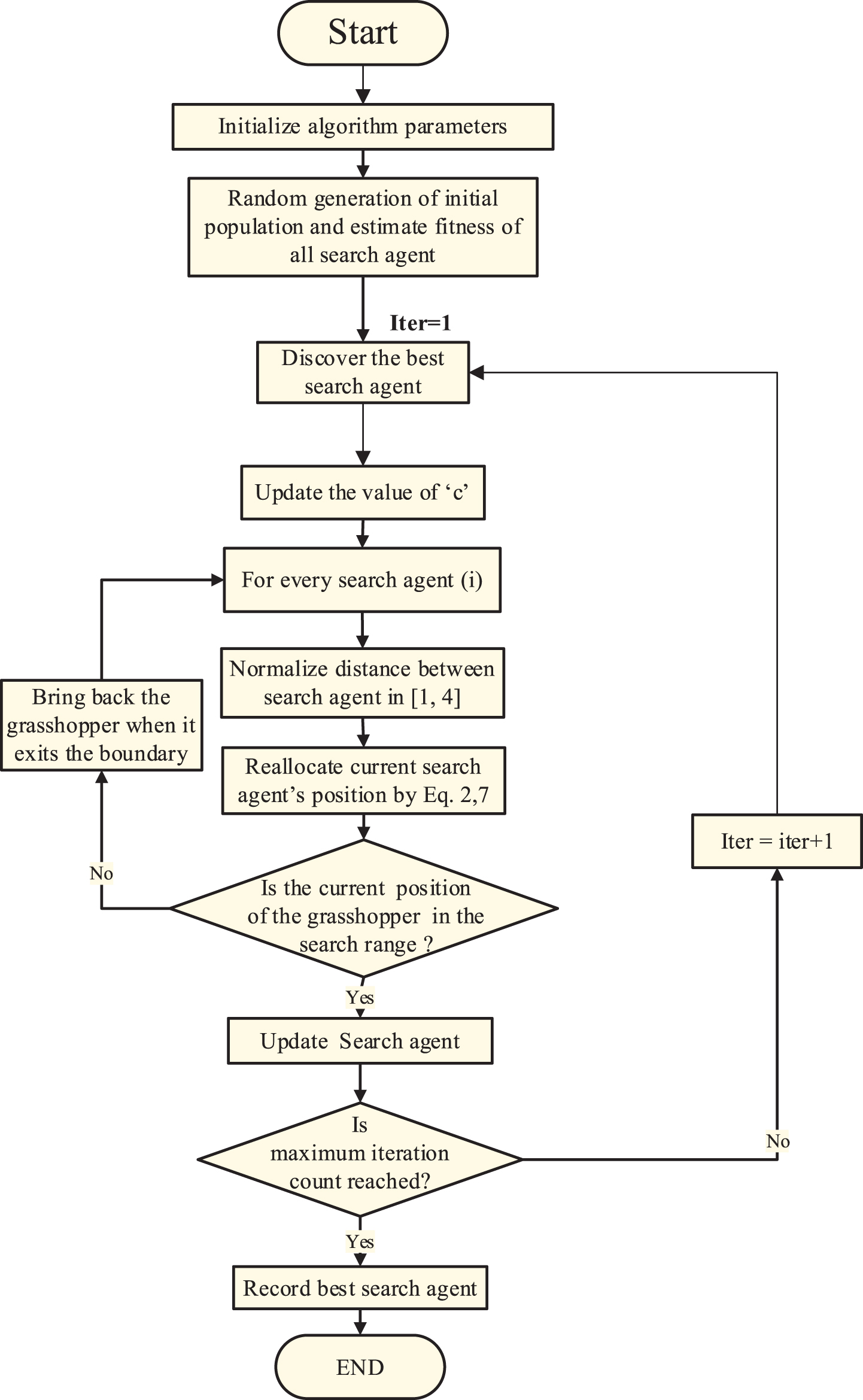
Flowchart of the MGOA.
The performance of various meta-heuristic algorithms for solving real engineering optimization problems is compared in this section. The various approaches demonstrate a fair comparison of meta-heuristic techniques.
Parameter settings of various meta-heuristic algorithms
A comparison of meta-heuristic techniques is more difficult in several respects because of the unique features of each type of meta-heuristic algorithm. Each meta-heuristic technique has a number of parameters to set before the execution of the algorithms. These parameters are essential components of an algorithm and can be modified to improve the algorithm’s efficiency. Table 1 provides a list of the parameter settings used for each meta-heuristic algorithm implemented. A 30 no. of search agents and 500 iterations are considered for all the algorithms. For every benchmark function each algorithm is run 30 times.
The initial parameters of the meta-heuristic algorithms
The initial parameters of the meta-heuristic algorithms
The MGOA’s performance is estimated considering standard benchmark functions. In [31], the benchmark functions expressions, ranges, dimension (Dim), and optimum solutions (f min ) are specified. The benchmark functions (unimodal and multimodal) are collected from [33]. The outcomes so acquired utilizing the proposed system are contrasted with algorithms such as original GOA, GA, IMBO, PSO, PBIL, ES, FPA, BA, and MBO.
Unimodal functions are appropriate test functions for any technique for the analysis of the exploitation ability. Table 2 shows that the proposed MGOA performs significantly better than the original GOA, GA, IMBO, PSO, PBIL, ES, FPA, BAT, and MBO algorithms for all seven 30-dimensional unimodal functions. Proposed MGOA outperformed the other algorithms for all unimodal functions (f1, f2, f3, f4, f5, f6, f7) and better than IMBO for five unimodal test functions (f1, f2, f3, f4, f7). The finding specified in Table 2 is evidence of the high exploitation capability of the proposed MGOA technique.
Comparison of techniques for unimodal function considering 30 dimensions
Comparison of techniques for unimodal function considering 30 dimensions
Simultaneously, multimodal functions comprise of numerous local optima. From Table 3, it is evident that MGOA explores the search space extensively to recognize the favorable regions. It is clear from Table 3 that the proposed MGOA gives considerably improved results compared with the above-mentioned algorithms in four out of six multimodal functions. The multimodal functions such as (f10, f11, f12, f13) outperformed the above-said algorithms and better than IMBO for three multimodal test functions (f8, f10, f11).
Comparison of techniques for multimodal function considering 30 dimensions
To evaluate the solution quality of the tested ten meta-heuristic algorithms, the average values and standard deviations have been obtained by MGOA, GOA, GA, IMBO, PSO, PBIL, ES, FPA, BAT and MBO algorithms over 30 independent runs. Table 2 and Table 3 indicate that the mean and standard deviation results obtained by the MGOA algorithm are significantly higher than the results obtained by the other meta-heuristic algorithms. The obtained average values and standard deviation values signify the robustness of the meta-heuristic approaches.
The proposed MGOA algorithm’s efficacy is compared with GOA [31], IMBO [33], GA [15], PSO [38], PBIL [40], ES [41], FPA [42], BAT [43] and MBO [44] as described in the literature [33]. For several previous studies, such as [33], these values were tested and incorporated. A comparison of the above-mentioned meta-heuristic techniques is given in Table 4.
Comparison of Meta-Heuristic algorithms
Comparison of Meta-Heuristic algorithms
Proposed adaptive fuzzy SSSC controller with PSS
As FLC deals with uncertainty, it can be used to improve the lead-lag controller performance. Two strategies are used for tuning of fuzzy control, for example, tuning of MF and rule tuning. For controller design, a triangular MF is generally adopted for real-time applications as its parametric functional depiction is economical.
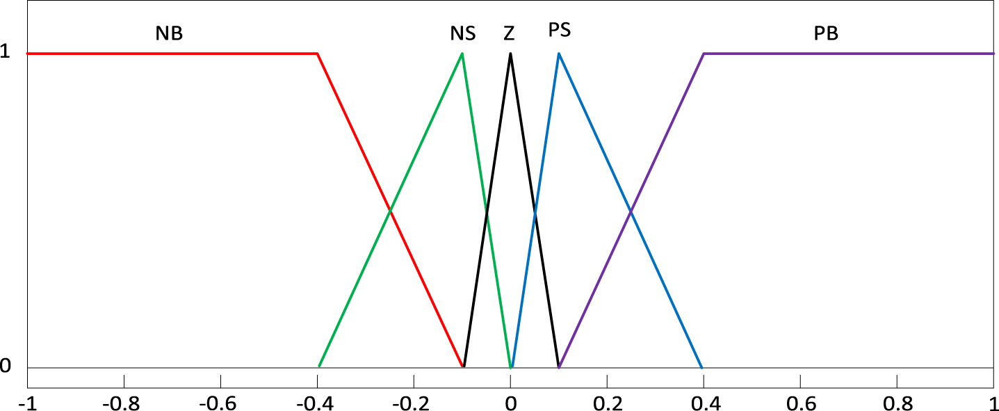
In this study, a triangular MF (with 50% overlapping) has been chosen. Also, an identical representation of the MF is normally chosen from the viewpoint of (i) computational competence, (ii) good usage of memory, and (iii) criteria for performance evaluation. For this analysis, the Mamdani MF is preferred, and the FLC output is calculated by the defuzzification center of gravity process. For simplicity, typical MFs and robust rule base procedures can be used to select applications and scaling factors should be adjusted for adaptive fuzzy lead-lag control [34–36]. The MFs for inputs and output are designated as PB (positive big), NB (negative big), PS (positive small), NS (negative small), and Z (zero). Figure 5 displays error, d/dt of error, and FLC output.
The Mamdani membership functions.
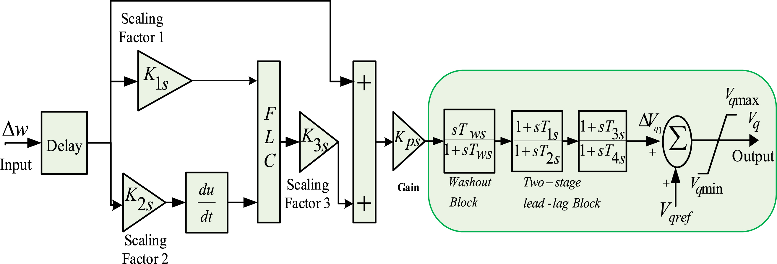
Triangular MF’s are cost-effective as compared to others for the real-time application. From the above point of view, triangular MF’s have been chosen here. Moreover, identical MF’s are supported for better utilization of memory, easy of analysis, better performance in addition to computational ability [37]. The inputs to FLC, shown in Figs. 6 7 are the error and d/dt of an error where speed deviation signal following a disturbance is taken as the error. To limit unreasonable control output limiter are provided for both SSSC and PSS based damping controller. The limiters ensure that over-voltage and low excitation problems will not arise due to proposed damping controllers.
Proposed adaptive Fuzzy lead-lag SSSC controller.
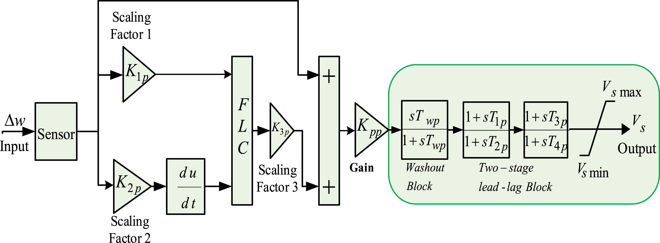
Proposed adaptive Fuzzy lead-lag PSS.
This paper considers speed deviation Δω to be the input signal for proposed controllers due to following reasons:
During steady state operation, the system maintains a balance between mechanical power input and electrical power output. This balance is disturbed during disturbance conditions and the power error flows into/drawn from the rotor. As a result, the rotor speed deviates with an effect of changing system power, current, voltage etc. As any disturbance is first reflected in the Δω signal, it is used in this paper as input signal for controller. From previous literature comparative study, it can observe that choosing Δω to be input signal for FACT controller for power system stability analysis improves controller performance.
The structure of proposed SSSC and PSS based controllers are displayed in Figs. 6 7 respectively. In order to get advantages of both lead (increase the stability or speed of response) and lag (reduce the steady-state error) compensator the lead-lag compensator is used as shown in Figs. 6 7. As a result, the system works with improved transient response, enhanced stability, and reduced steady-state error. The washout block is a high-pass filter which filtered out the unwanted low frequency oscillation present in the Δω.
Figure 6 illustrates the structure of adaptive fuzzy lead-lag SSSC controller where the input signals to the controller is the speed deviation of generator. As the location of SSSC is generally far away from the location of generator, delay block is included in Fig. 6.
Figure 7 shows the structure of adaptive Fuzzy lead-lag PSS controller where the input signal to the controller is the speed deviation of generator. As PSS is located near the generator, only sensor is included in Fig. 7.
Transfer function with appropriate time constants is used to model delay and sensor in the SIMULINK model of system under study.
The specified gain values ensure required steady-state error margin, and the remaining design consideration will focus on the required phase margin and gain crossover frequency. Proper design of the lead-lag compensator requires finding suitable values of time constants T1-T4 so that the compensator poles and zeros will be placed appropriately. The PSS output (Vs) will be added to excitation system reference voltage (V
ref
). In this paper the value of time constants of washout block is considered to be T
ws
=T
wp
=10. With this the remaining controller parameter K1s, K2s, K3s & K1p, K2p, K3p are need to be estimated.
The effectiveness of controller is measured in terms of its transient performance. Parameters such as errors, settling time and percent overshoot are required to be small. Controller design is vital in order to get desired transient performance. Optimization methods are very important in designing the controller parameters to achieve aforementioned objectives. In this paper, ITAE is used as objective function to be minimized. The ITAE based controller tuning can achieve reduce peak overshoot and settling time which is not possible with ITSE and ISE based tuning. ISE criterion integrates the square of the error over time leads to low amplitude oscillation in transient response. The settling time obtained with ITAE tuning is less compared to ISE tuning method. Furthermore, ITAE tuning leads to sluggish initial response which is important to avoid sustained oscillation.
When a disturbance occurs in the system, it may result in imbalance between the total power generation and consumption (load plus losses) power. The difference power enters into rotor and hence rotor accelerates or decelerates. As any disturbance is immediately reflected in rotor speed, the controller is designed to minimize the Selected Performance index J (time scaled Δω Modes) by appropriate control action.
The low frequency oscillations are affected by the parameters like rotor speed deviation, tie-line power and power angle deviation. Therefore, the single objective may be chosen to minimize any or more of the above deviations. Among the three parameters rotor speed deviation has more impact on damping the low frequency oscillations. The objective function as ITAE of the rotor speed deviations signal Δω is expressed in Equation (11) as
Where, Δω is the change in speed; to obtain the objective function, a fault is coupled to the system which is under evaluation. The prescribed range of the damping controller and PSS are controlled in a limit. The approach is thus seen as the issue of optimization:
The optimized gains (K pi ) values are in between 0.01 to 100. The values of time constants (T1i, T2i, T3i & T4i) and scaling factors (K1i, K2i & K3i) are ranges in between 0.01–5 where i = S for SSSC and i = P for PSS. Thus, paper employs MGOA algorithm to optimize the system objective and estimate optimal set of controller parameters to achieve this.
SMIB system
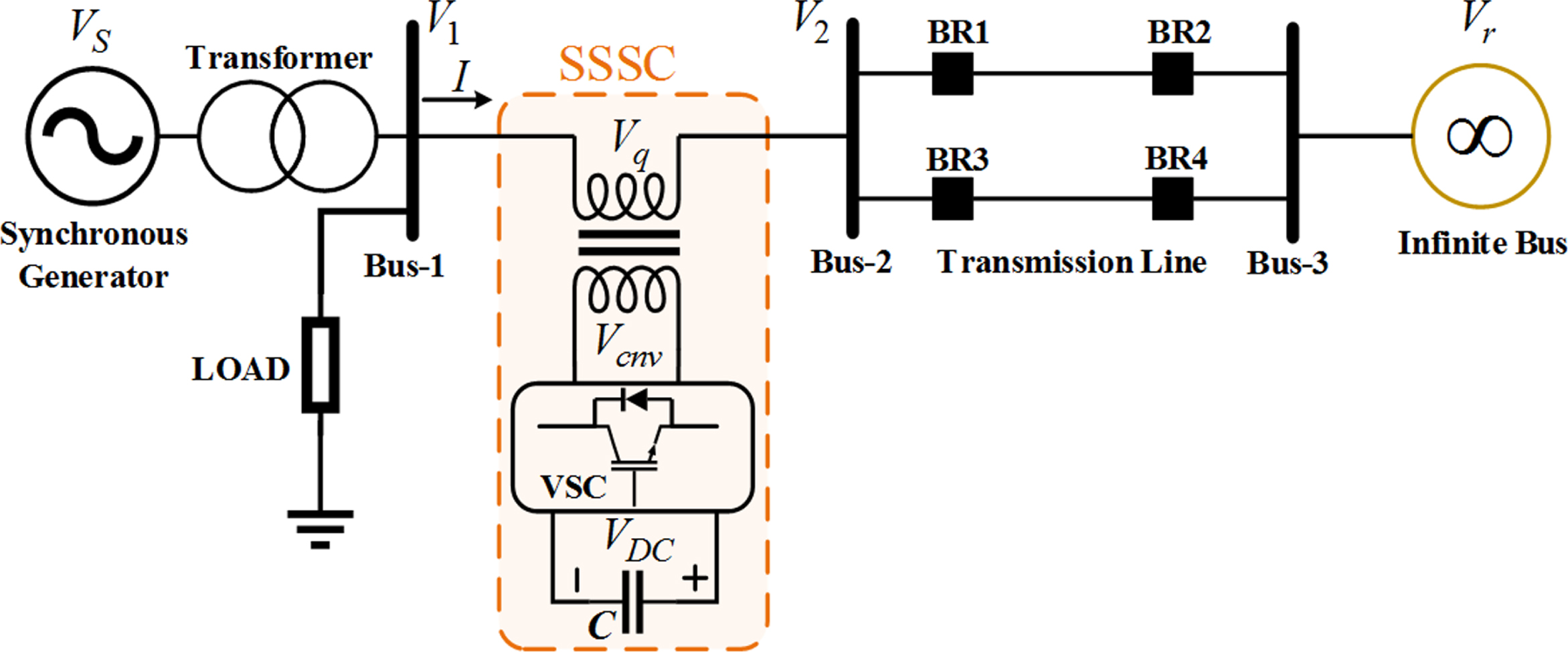
The proposed MGOA is now applied to a real-world design problem for the test system displayed in Fig. 8. In Fig. 8, the transformer is represented by T; the generator terminal and infinite bus voltages are represented by VT and VB respectively; while V1 and V2 are the bus voltages, the output voltage of the SSSC converter and the DC voltage source is represented by Vcnv and VDC respectively; the line current is I and the total real power flow in the transmission lines and that in one line are each represented by PL and PL1 respectively.
SMIB system with FACTS controller.
The SMIB system developed in MATLAB/SIMULINK environment with proposed controller is displayed in Fig. 9. This system is consisting of a generating unit that is connected to infinite bus by a double-circuit transmission line. In the present study, ode23tb (stiff/TR-BDF2) solver which is a variable-step with a maximum time step of one cycle of the fundamental frequency (1/60 s) has been used as recommended in literature [4, 5].
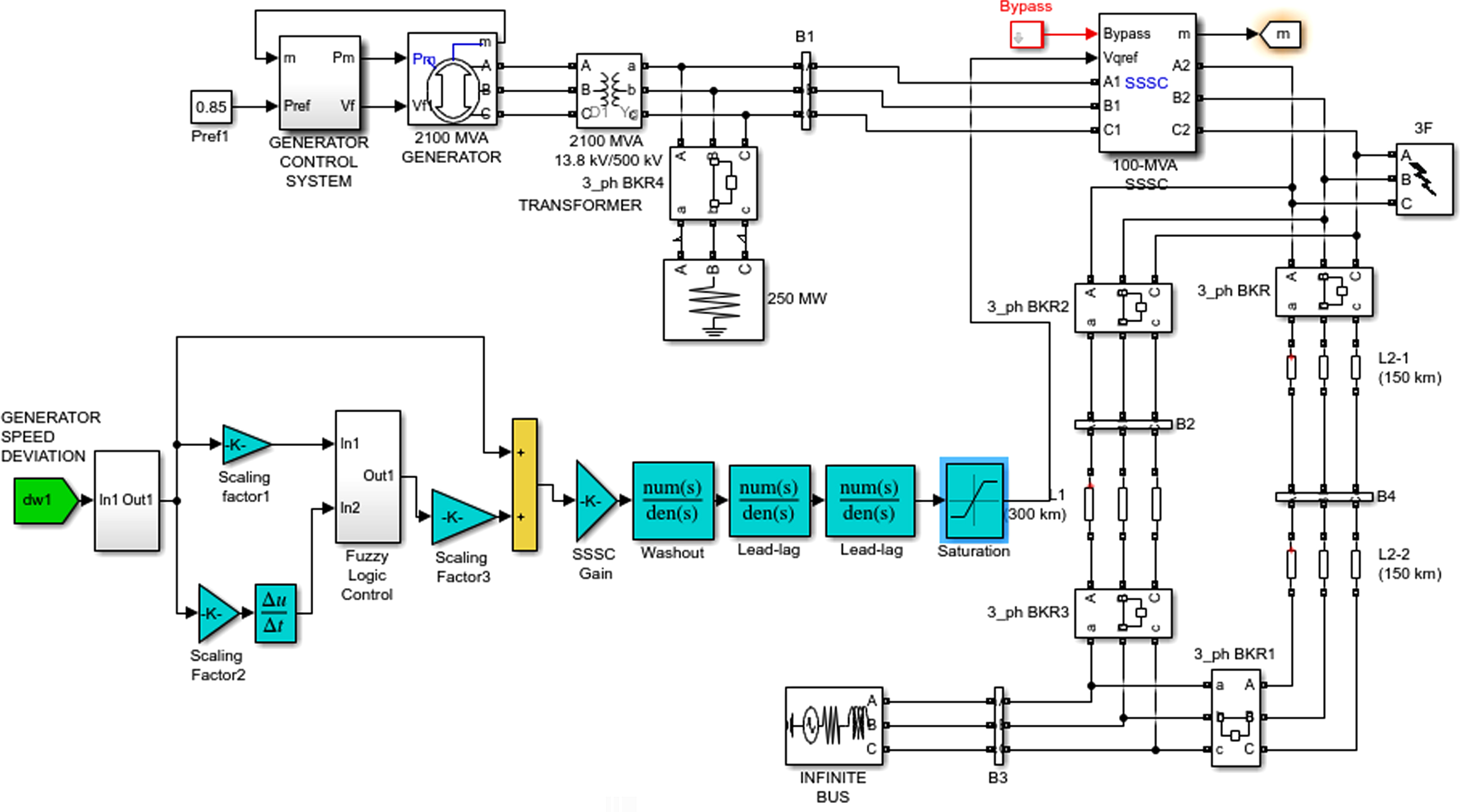
Proposed MATLAB/SIMULINK model of SMIB.
The generators are represented by a sixth-order model which is available in Sim Power Systems (SPS) library of MATLAB/SIMULINK. The model considers the dynamics of the stator, field, and damper windings represented in the rotor reference frame. The machines are equipped with HTG and Excitation system. These components are present in the subsystem represented by “Generator Control System” (Reg_M). The generator parameters including the delta_omega signal are collected using ‘busselector’ in the “Generator Control System” subsystem and used for controller design.
To demonstrate the supremacy of the proposed approach, lead-lag controller is initially considered. A 3-phase 5-cycle fault is applied in the middle of one transmission line for objective function calculation, which is cleared by 5 cycle line outage. The controller parameters for MGOA optimized lead-lag structure are provided in Table 5. In the next step, proposed adaptive fuzzy lead-lag controller is implemented. For comparison, PSO, GA and original GOA are also applied for tuning adaptive fuzzy lead-lag controller parameters. The parameters for the optimized controller are specified in Table 6. The comparative ITAE values with different approaches are displayed in Table 7. It can be observed that the proposed MGOA tuned adaptive fuzzy lead-lag controller acquires a minimum objective function value compared to other techniques. The % decrease in J value with proposed modified GOA technique compared to recent published GOA, well established GA and PSO are 21.46 %, 34.30 %, and 47.09 % respectively.
MGOA optimized lead-lag structured PSS and SSSC parameters for SMIB (i = S for SSSC and i = P for PSS)
MGOA optimized proposed SSSC and PSS parameters for SMIB system (i = S for SSSC and i = P for PSS)
Comparison of PSO, GA, GOA and MGOA technique
The dominance of the proposed controller optimized by MGOA is displayed in Fig. 10 in contrast to other techniques such as PSO, GA and GOA. It is visible from Fig. 10 that, in comparison to PSO, GA and GOA techniques, better system response with minimum undershoot is obtained with proposed MGOA technique.
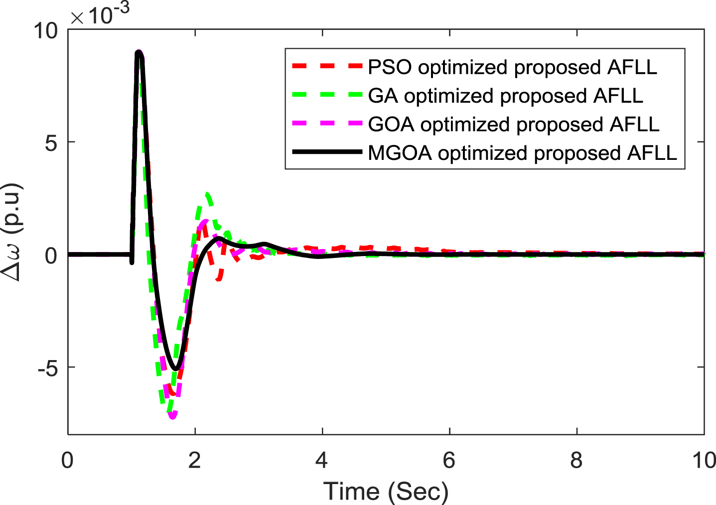
Speed deviation of proposed controller considering PSO, GA, GOA and MGOA techniques.
To investigate the viability of proposed controller several contingencies are taken as follows.
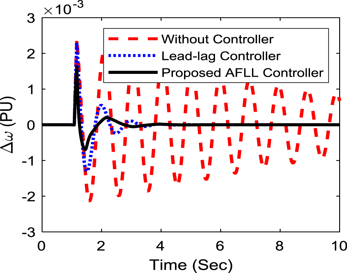
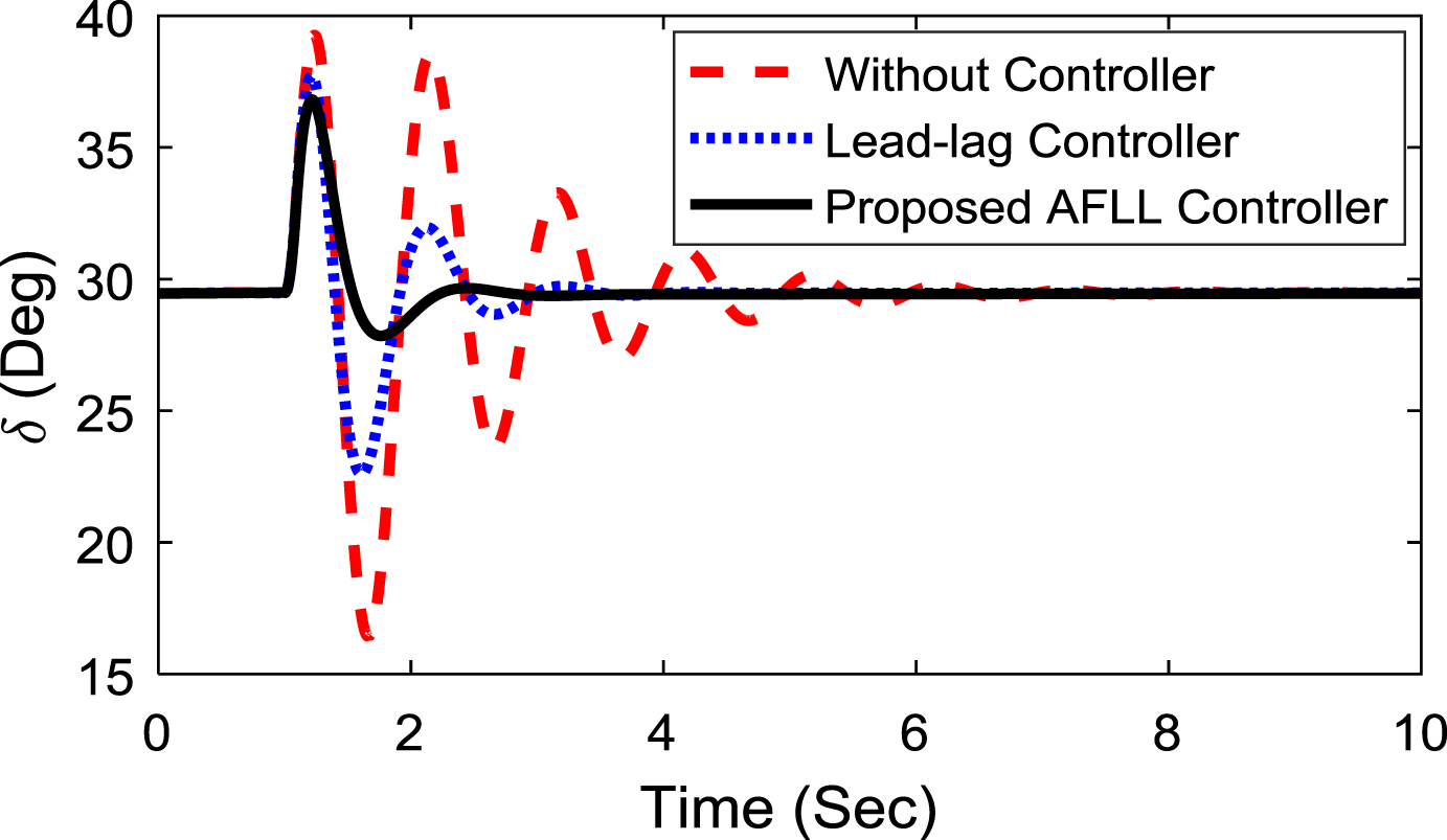
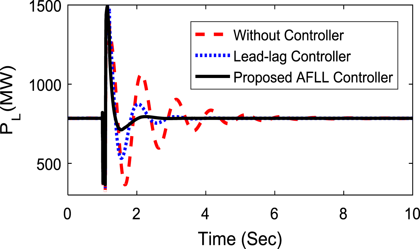
Scenario 1: Initially, the performance of the controller is investigated at nominal loading condition. A 3-phase fault is applied near bus 2. The duration of fault is taken for 5 cycles. The duration of fault is resolved by tripping the faulted line and the line is reclosed after 5 cycles. (Pe = 0.85p.u. δ0 = 53.50). Figures 11–14 display the speed deviation response (Δω) in p.u, power angle response (δ) in degrees, tie line power (PL) in MW and SSSC injected voltage (V q ) in p.u under severe disturbance. Figures 11–14 demonstrates that the proposed controller tuned by MGOA has a superior damping characteristic than others. To show the superiority of the proposed controller, two more cases have been taken into consideration. Figures 15, 16 shows the speed deviation response (Δω) in p.u of the study of operation under faults open and short circuited at generator bus. It is also noted that the proposed controller provides improved response compared to conventional lead-lag controller.

Nominal loading speed deviation response.
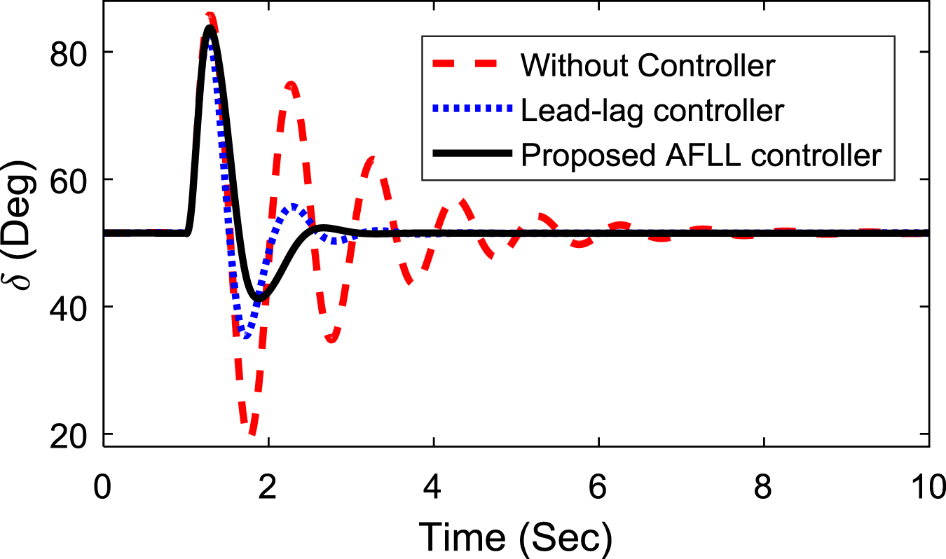
Power angle response.

Tie-line power.
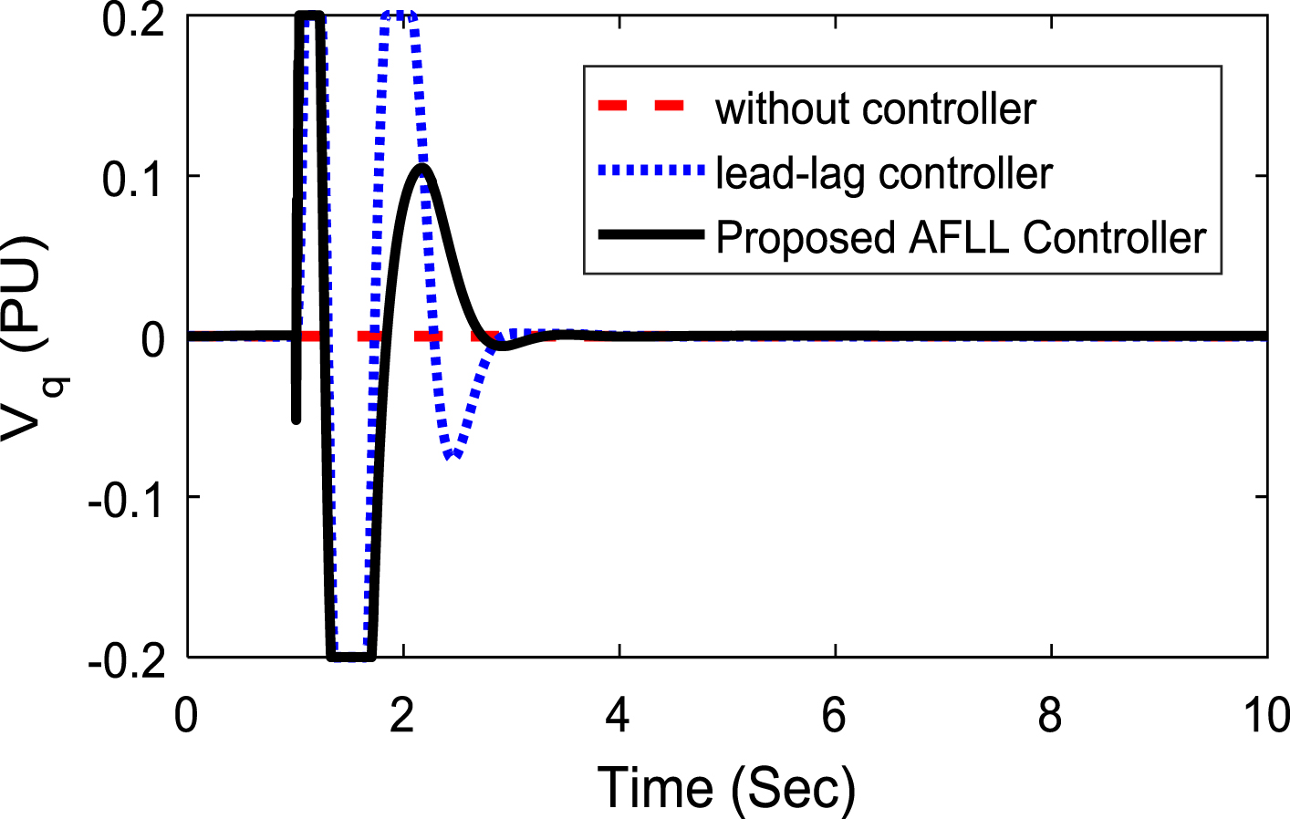
SSSC injected voltage.
Nominal loading speed deviation response under faults Open.

Nominal loading speed deviation response under Short circuited at generator bus.
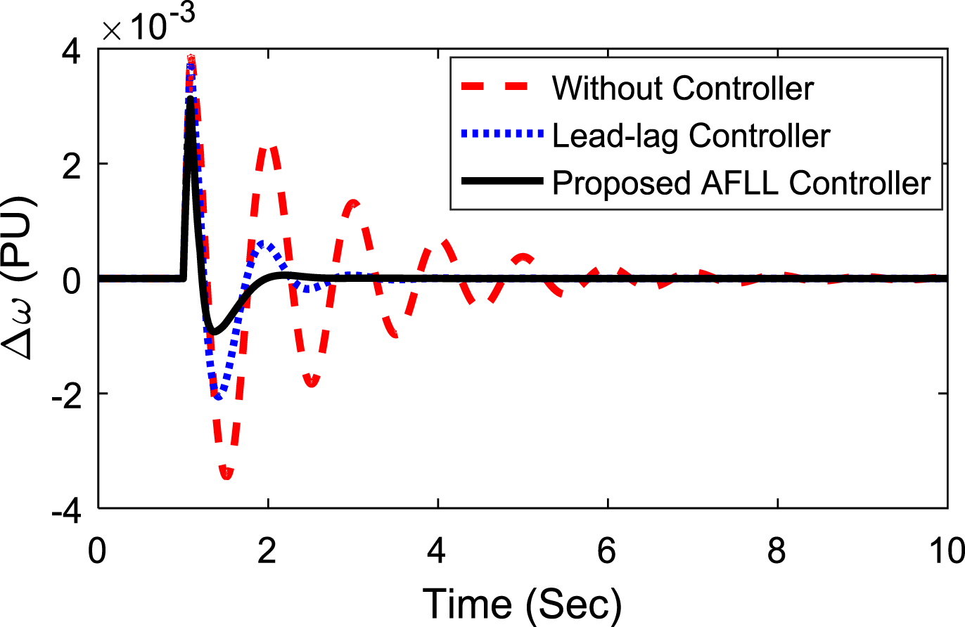
Scenario 2: Furthermore, the condition of loading is changed to light loading (Pe = 0.5 p.u., δ0 = 29.20). A 3-phase fault is set at the mid-point of the transmission line. Thereafter, the load is removed close to bus 1. Under this contingency, the system responses are shown in Figs. 17–19 clearly illustrating the strength of the proposed controller for changes in (i) operating condition, and (ii) type of disruption.

Light loading speed deviation response.
Light loading power angle response.
Light loading tie-line power response.
Scenario 3: Finally, controller efficiency is verified in heavy loading conditions (Pe = 1.0 p.u., δ0 = 60.70). For 200 ms situation, one of the parallel lines is tripped here. Under this contingency, the response of speed deviation is displayed in Fig. 20. It is observed that the system oscillations are dampened rapidly with the proposed controllers in comparison with others.
Table 8 gathers the ITAE values for the above three scenarios for improved clarification of the enhancement by proposed approach. It can be found that the least ITAE values with the MGOA optimized adaptive fuzzy lead-lag controllers are obtained for various scenarios.
Heavy loading speed deviation response.
Different cases of ITAE values considering SMIB system
The multi-machine power system presented in Fig. 21 is considered in the next stage and developed in MATLAB/SIMULINK environment is shown in Fig. 22. The system consists of two areas and with the help of a tie line, the two areas are connected. The essential parameters for the system are shown in references [16, 39].
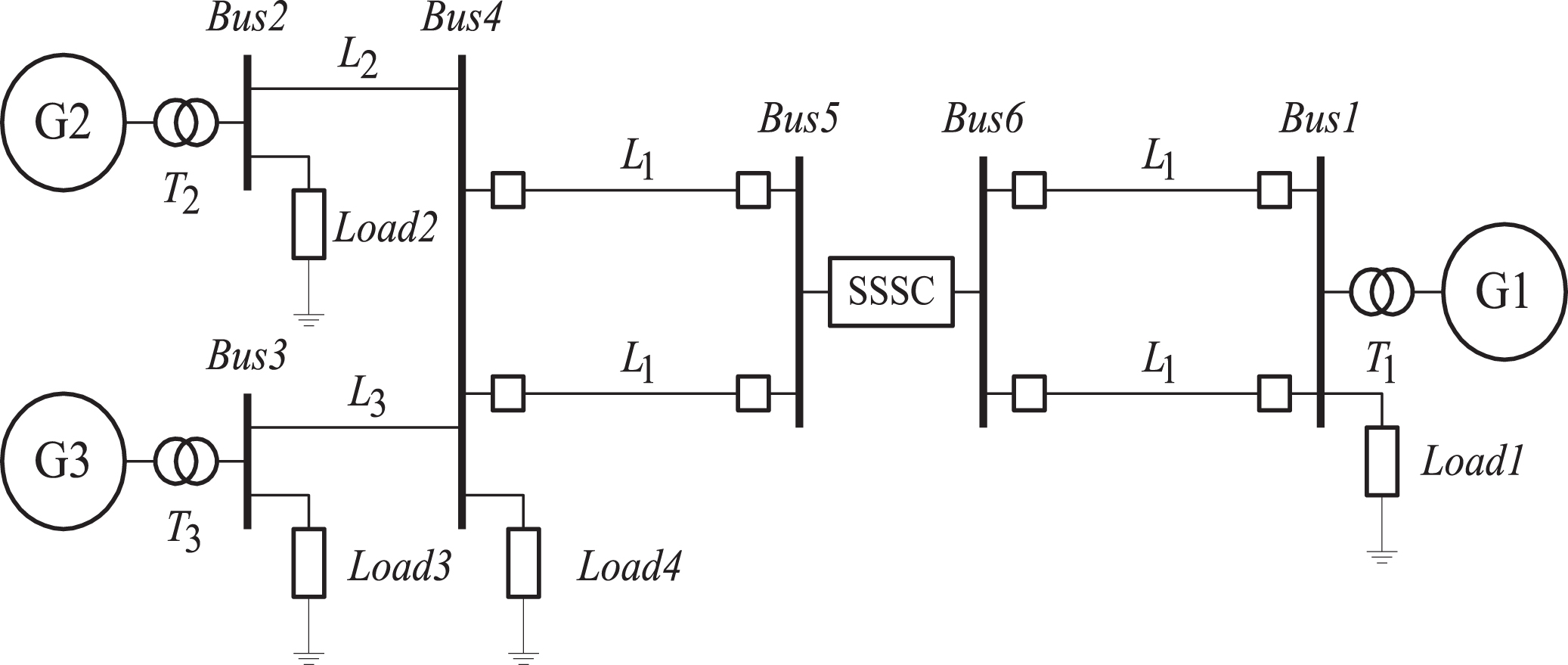
Three-machine system.
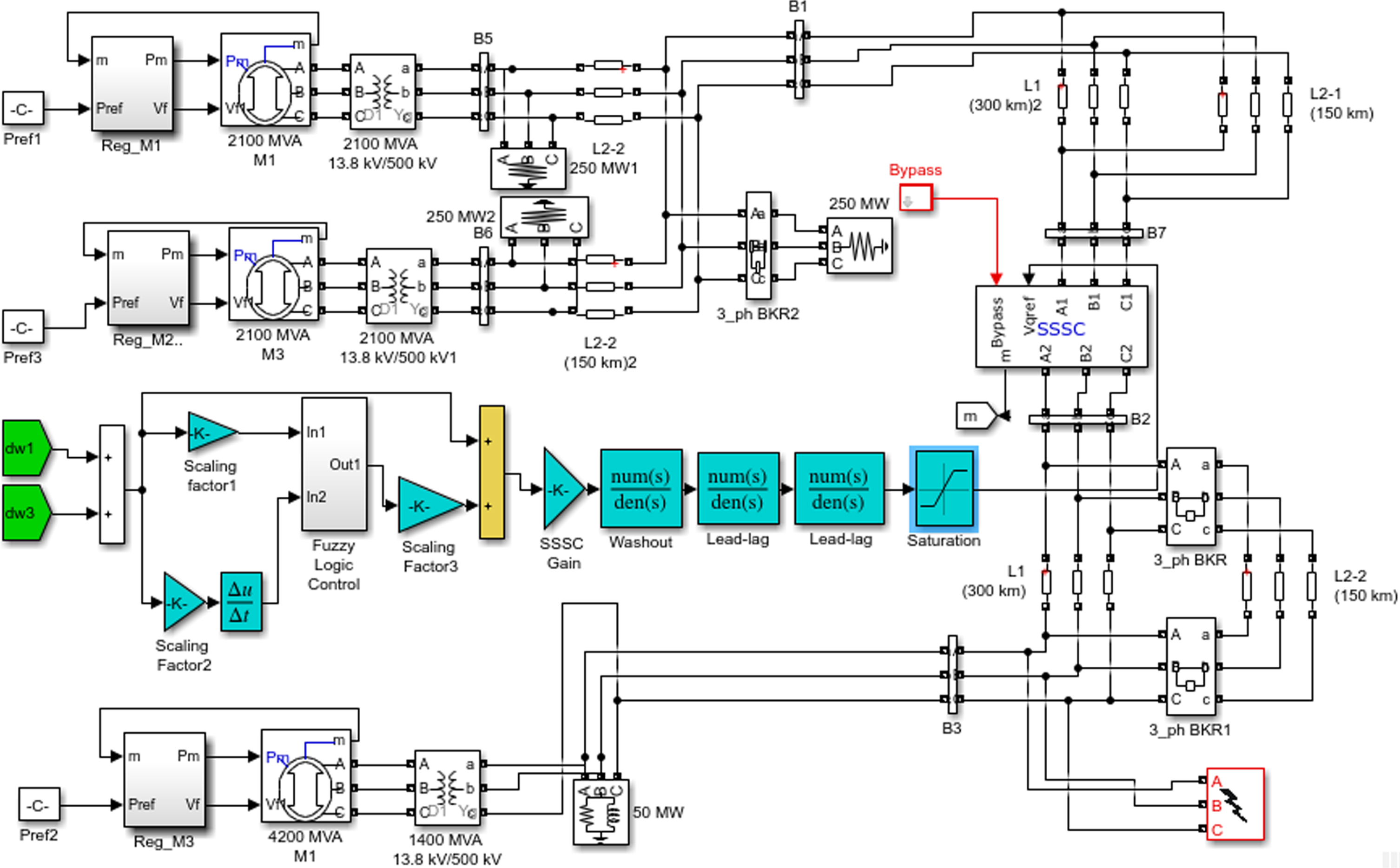
Proposed MATLAB/SIMULINK model of multi-machine system.
The location of series FACTS devices constitutes a major step in the application of FACTS devices in power systems. The location depends on the objectives such as reducing a specific line’s actual power loss, reducing the total system’s real and reactive power loss, and overall system power transfer. The sensitivity analysis leads to rate of changes in one parameter due to variation of other parameter value of the system. Depending on the required objective, sensitivity analysis can be done to determine the optimal location of SSSC in a large power system. Keeping in view of our objective of power system stability improvement, the SSSC controller is incorporated in between bus 5 and bus 6.
The objective function is defined as:
To design the adaptive fuzzy SSSC controller, similar approach as used in single machine is followed. The optimized controller parameters for lead-lag and adaptive fuzzy lead-lag controllers are provided in Table 9 and Table 10 respectively.
Proposed MGOA tuned lead-lag structured SSSC and PSS parameters (i = S for SSSC and i = P for PSS)
Proposed MGOA optimized adaptive Fuzzy lead-lag structured SSSC and PSS parameters (i = S for SSSC and i = P for PSS)
Here, various disturbances cases are considered as given:
Case 1: Three-phase, five-cycle fault close to bus 3;
Case 2: Detachment of load for small time;
Case 3: Three-phase self-clearing fault at bus 3.
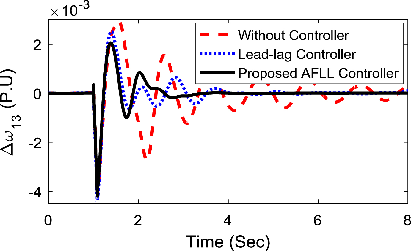
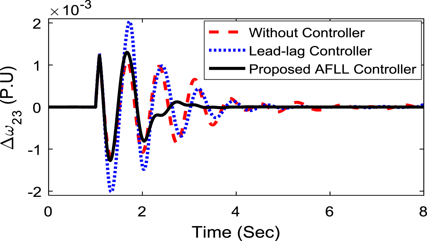
Figures 23–28 The system responses to the above three instances indicate that the suggested MGOA optimized adaptive fuzzy SSSC controller has better features relative to the MGOA optimized conventional lead-lag controller. From the Figs. 23–28, it is observed that both inter-area and local oscillation modes in the lead-lag controller and without controller are extremely oscillatory. The proposed approach significantly enhances the stability by damping these oscillations through properly modulating the voltage applied by the SSSC.
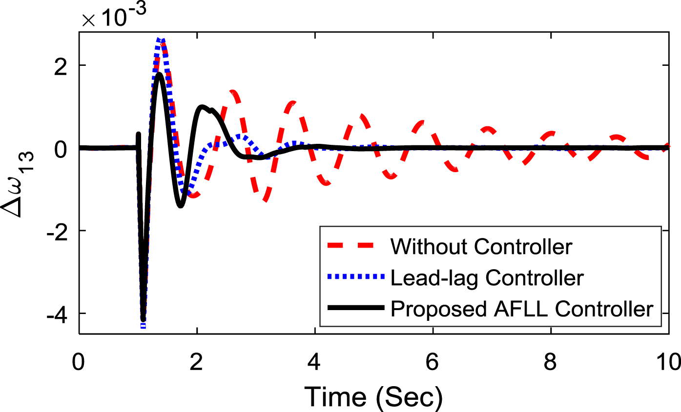
Inter-area oscillations response.
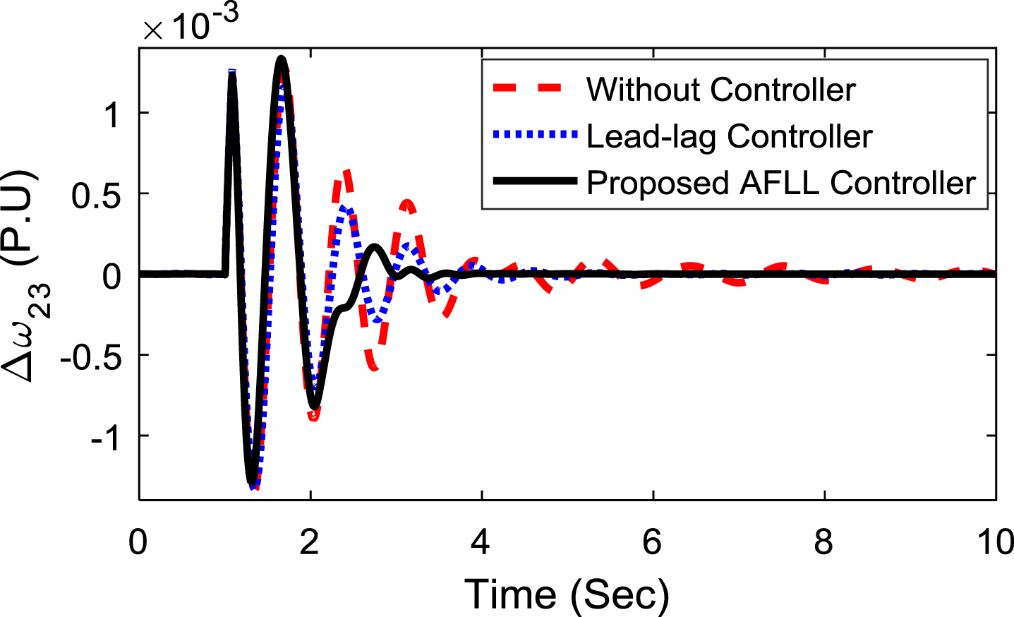
Local-area oscillations response.

Inter-area oscillations response.

Local-area oscillations response.
Response of inter-area oscillations.
Response of Local-area oscillations.
Different cases of ITAE values for multi-machine system
Stability problems could be investigated for a distribution network with various types of distributed generation sources and FACTS controllers, and controls could be designed to enhance system efficiency. The latest work can be expanded for SSSC with energy storage such as SMESS, BESS, and electric vehicle battery for enhancing the power system stability.
In this present work, adaptive fuzzy lead-lag structured SSSC and PSS damping controller are proposed for stability improvement in power system. The controllers are coordinated designed using a modified GOA technique where modification of the exploration and exploitation stages has been introduced in original GOA algorithm to improve its performance. The MGOA’s performance evaluation is verified by applying it to standard benchmark test functions. Further, dominance of MGOA as compared to other techniques such as PSO, GA and GOA are demonstrated for power system stability improvement under various disturbances scenario such as different loading conditions and disturbance like self-clearing fault, three-phase fault and a short duration temporary large load excursion. It is noticed that MGOA outperforms original GOA and other similar heuristic optimization technique in benchmark test functions. It is also observed that adaptive fuzzy lead-lag structured damping controllers provides better system response compared to conventional lead-lag structured controllers. Also, MGOA optimized controllers are superior to PSO, GA and GOA optimized controllers for both SMIB and multi-machine power system. The % decrease in J value with proposed modified GOA technique compared to recent published GOA, well established GA and PSO are 21.46 %, 34.30 %, and 47.09 % respectively in SMIB system. Also, The % decrease in J value with proposed modified GOA technique compared to recent published GOA, well established GA and PSO are 33.25 %, 27.00 %, and 22.87 % respectively for multi-machine system.
Footnotes
Appendix
System data: All data are in pu unless specified otherwise.
(a) SMIB system:
Generator: SB = 2100 MVA, VB = 13.8 kV, f = 60 Hz, H = 3.7 s, RS = 2.8544e- 3, X
q
= 0.474,
(b) Multi-machine Power system:
Generators: SB1 = SB2 = 2100 MVA, SB3 = 4200 MVA, H = 3.7 s, VB = = 13.8 kV, f = 60 Hz, RS = 2.8544e- 3, X
q
= 0.474,