
Abstract
This paper presents a data-driven control approach for a five-bar robot with compliant joints. The robot consists of a parallel mechanism with compliant elements that introduce uncertainties in modeling and control. To address this fact, it is implemented a model-less data-driven controller based on a Feedforward Neural Network Module (FNNM) that identifies the inverse dynamics of the robot. The FNNM is incorporated into a coordination of Feedforward Control Method (CFCM) to achieve precise trajectory tracking. Experiments compare the compliant joints robot to a bearing-joint robot performing pick-and-place tasks from 0.15 to 3.15 Hz. Results show the compliant robot maintaining trajectory tracking up to 1.25 Hz with a Root Mean Square Error (RMSE) of 9.02 mm.
Introduction
A parallel robot is a type of robot that has one or more closed kinematic chains. Parallel robots are often used in applications where high accuracy and stiffness are required, such as machine tools, astronomical tracking, and space simulators [4, 9, 11, 21].
Parallel robotic manipulators offer several benefits, including high stiffness, dexterity, payload capacity, and the ability to achieve precise positioning. One notable advantage is that parallel robots are theoretically expected to exhibit greater accuracy compared to serial robots. This is due to the fact that errors present in the individual links of parallel robots tend to be averaged out, rather than accumulating as seen in serial robots [3, 7, 19, 20].
Moreover, parallel robots have the advantage of high speed. This speed is attributed to the arrangement of motors on a stationary frame, resulting in reduced inertia that needs to be overcome during motion. As a result, parallel robots are well-suited for tasks that require high-speed operations.
Compliant mechanisms utilize flexibility rather than articulated joints to transmit forces and motions. They offer advantages like reduced wear, friction, and backlash compared to rigid-body linkages. Compliant mechanisms are increasingly being applied in precision engineering domains like micro-positioning systems, medical devices, and robotics [5, 6, 14].
Some of the research is focused on the control of compliant robots. Some control schemes are done by implementing Sliding mode controllers such as in [18, 22] or some variations, such as Variable Boundary Layer Sliding Mode Control (VBSMC) to try to ensure a safe operation due to compliant joints introduce uncertainties and can store a dangerous amount of energy [10].
Cartesian control is an important technique for controlling the motions of robotic manipulators. It involves specifying the motions in terms of the X, Y, Z coordinates of the robot’s end-effector, rather than joint angles.
Cartesian control simplifies motion planning and coordination when the task is defined in Cartesian space, such as following a straight line path. It handles nonlinearities of joint coordinates through linear Cartesian space. Overall, Cartesian control brings robot programming closer to human understanding and makes tasks like pick-and-place much easier to specify and execute precisely. This makes industrial robots more versatile and capable [1, 12].
In the literature exists approaches about controlling parallel robots. In [8] they develop an offset-free nonlinear model predictive controller to achieve zero steady-state error. Experiments on a 3-DOF planar cable-driven parallel robot with cables and propellers validate the tracking of trajectories, disturbance rejection, and vibration damping.
Reference [2] presents experimental studies on the vision-based control and identification of planar cable-driven parallel robots. The adaptive sliding mode controller that incorporates a model identification system shows the best performance.
In [16] are formulated two methods for detecting collisions and identifying external torques acting on a parallel Delta robot. A model-based approach uses a generalized momentum observer and least squares identification of friction and modeling error parameters. The model-less method trains a neural network to predict joint torques without collisions.
The previously mentioned work shares a characteristic, the controllers are model-based in [2, 8]. In reference [16] the data-set is obtained through success and fail cases with the model-based controller of a Delta robot without compliant elements. However, the static and dynamic modeling of five-bar mechanisms with compliant elements remains challenging. Therefore, in the present work it is proposed a fully data-driven controller with a PID and Feedforward Neural Network with online training as the controller to avoid the dynamic modeling.
In this paper, we propose a data-driven vision-based control approach using a Feedforward Neural Network Module for the trajectory tracking control of a parallel robot with compliant joints. Experimental validation of our proposal is performed on a five-bar parallel robot with three bearing and three compliant joints, following a semicircular trajectory. Several experiments are performed at different frequencies of the semicircular reference.
The following sections explain the experimental setup which describes the physical five-bar robot prototype with compliant joints that was used in the experiments. In the controller section it explains the data-driven control approach using a Feedforward Neural Network Module and PID feedback. The results and discussion section presents experimental results comparing the compliant joint robot and a bearing-joint robot performing trajectory tracking tasks at different frequencies. The paper finishes with some conclusions.
Experimental setup
As previously said, the dynamic system is a five-bar robot with compliant joints.
Figure 1 shows a diagram of the five-bar robot, where L1 = L2 = 0.147 m, L3 = L4 = 0.322 m and L5 = 0.400 m. The robot’s links are made out of an aluminum bar of 25.4 mm in width and 6 mm in height. The base of the robot is made out of PETG 3D printed. The compliant joints are TPU 3D printed. The measurements of the compliant joints are 48 mm in length, 30 mm in width and 10 mm in height.
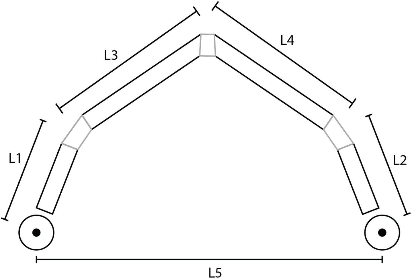
Robot scheme.
The experimental setup is a pair of Crouzet™ 24 V Brushed DC motor part number 89830912. Each motor has a two-channel incremental HEDS 5500 encoder, with 1000 pulses per revolution. The motors are connected to a Pololu Dual VNH5019 Motor Driver Shield which operates from 5.5 to 24 V and can deliver a continuous 12 A (30 A peak current). Besides, the motor driver supports up to 20 kHz PWM frequency. The motor driver is connected to a 24 V at 6.5 A generic power supply. The Data Acquisition Card is a Sensoray 826 Multifunction analog/digital I/O board. The joints tested against the compliant ones are common bearings. The motion capture system is an array of 8-camera Vicon MX™ (Vicon, Oxford, UK), sampled at 666.667 Hz using Vicon Tracker™ 3.9 software. There are 12 custom-made markers in the shape of a hemisphere on the robot. Each link contains three markers, and one marker is placed strategically at the robot’s end-effector. As a base framework there are placed five markers on the optic table where the robot’s base is attached.
Figure 2 displays the array of markers directly from the Vicon Traker™. The coordinates of the markers are obtained through the Vicon DataStream SDK running on a C++ program.

Vicon Traker™ compliant joint robot visualization.
The controller is applied in the Cartesian space to follow the desired trajectory.
The desired trajectory is proposed as a semicircle SC [x n , y n ], that is used as a pick-and-place task as it expressed in Equation (1)

The data-driven controller is a modified version of the Coordination of Feedforward Control Method (CFCM) [13] which uses a Feedforward Neural Network Module (FNNM) to identify the inverse dynamic model of the system.
In [13], it is demonstrated that a Two-Layer FNN is capable of identifying the inverse model of a nonlinear system using online training. Thus, a Two-Layer FNN is used to identify the inverse dynamics in this experimental setup.
Figure 3 presents the inverse identification module. In this case, vector x is a vector of the n-delays-1 of the respective coordinate C
x
or C
y
of the end-effector. The number of delays is related to the input layer of the FNN. In this case, the number of inputs to the FNN is 15. Thus, the x vector is defined as in Equation (2) Inverse model scheme.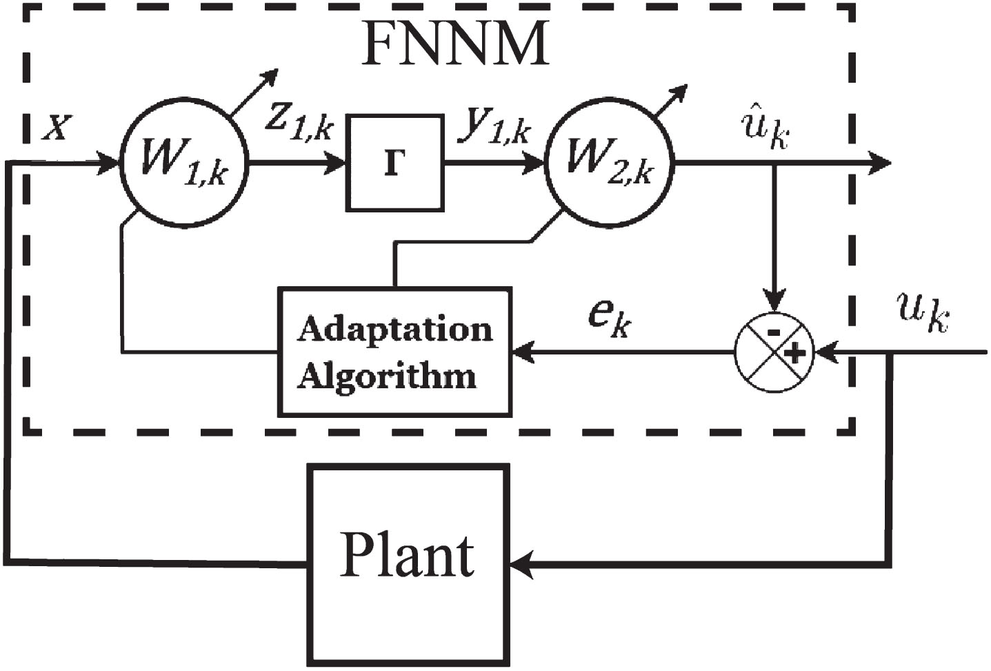

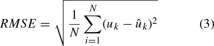
The result when using 15 neurons in the FNN inverse model identification shows a Root Mean Square Error (RMSE) of 1.3 × 10⁻³mm. The RMSE formula used is:
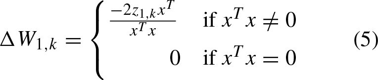
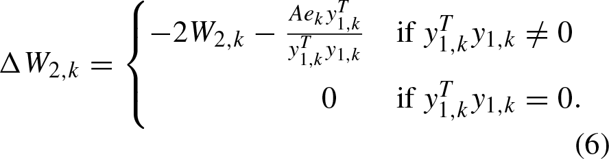
Weights W1 and W2 of the network are updated online to control the error dynamics as explained in [13], where the weight matrix update equations are given by

The block Γ of Fig. 3 corresponds to the activation function. In this project, the hyperbolic tangent was used as an activation function.
The block diagram of the controller is shown in Fig. 4. Where B is the selected System Response, G is the Feedback Loop Controller, P is the plant and y r is the Reference Signal. Further reading of the design of CFCM can be done in [13, 15, 17].
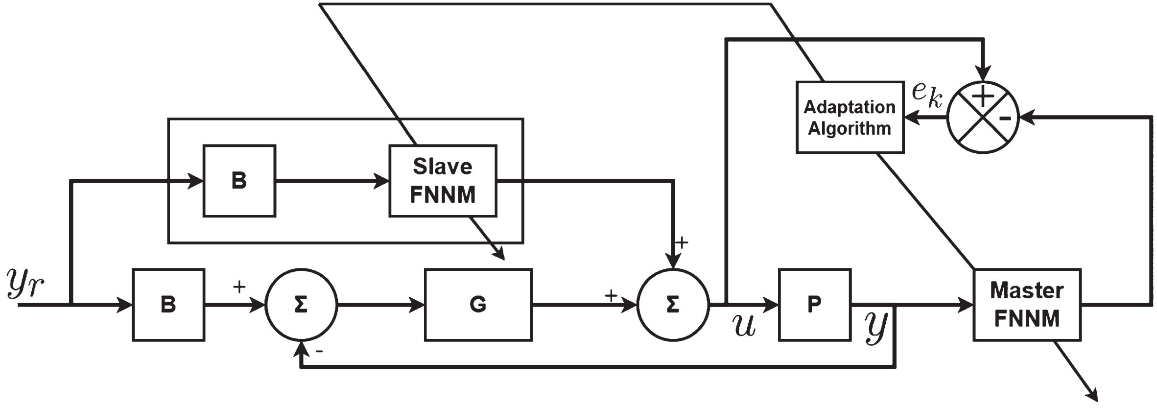
Block diagram of the FNNM controller [13].
The block B is chosen to have the form:


In this case, the feedback Loop Controller G is a PID controller that is tuned by a trial and error method.
The result of the tracking task of the five-bar robot is shown in Fig. 5. The compliant joint robot is compared with a common bearing-joint robot under the same environment. As it can be seen both robots behave similarly under a pick-and-place task at a frequency of 1 Hz.

Tracking task at 1 Hz.
Figure 6 shows the pick-and-place task at a frequency of 1.2 Hz. The compliant joint robot withstands the change in the frequency rather than the bearing-joint robot.
The compliant joint robot exhibited lower error at a slightly higher frequency due to its natural compliance and shock absorption. Its softer, flexing joints can accommodate quick motions better than stiff, rigid joints. The rigid bearings of the other robot have more reflected inertia and tighter dynamic coupling between joints, amplifying positioning errors as frequency increases. The flexibility allows the compliant robot to isolate vibrations and high frequency disturbances within each joint’s compliance, rather than propagating throughout the structure. This experiment highlights a potential benefit of compliant/flexible robots in dynamic isolation and attenuation of errors at high speeds or operating frequencies. Further testing could better characterize the frequency responses and explore optimizing joint stiffness.

Tracking task at 1.2 Hz.
Therefore performing a frequency sweep from 0.15 Hz to 3.15 Hz on both robots we obtain a frequency response of each robot.
Figure 7 shows the nonlinear behavior of the compliant joint robot during the frequency sweep. The last frequency until a big increment in the error is produced is at 1.25 Hz of the pick-and-place task. Then the error keeps incrementing during the experiment until it is finished.
Figure 7 also shows the behavior of the bearing-joint robot during the frequency sweep. The experiment was stopped at a frequency of 2 Hz, at which the bearing-joint robot changed its pose and it was not controllable anymore.
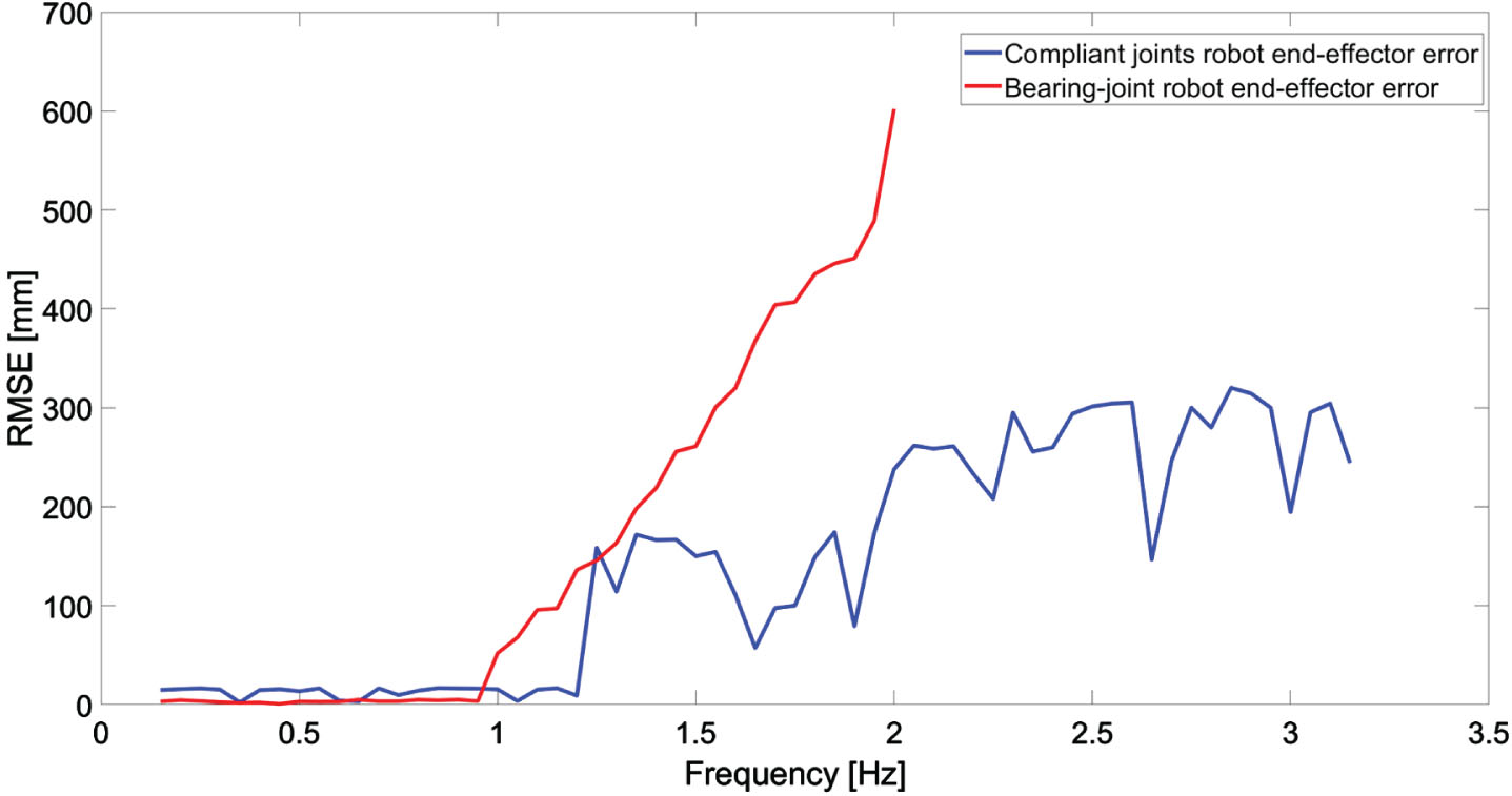
Frequency sweep of compliant joints robot.
The behavior of the compliant joints robot for high frequencies is shown in Fig. 8 where the compliant joints robot changes the desired trajectory to different trajectories.
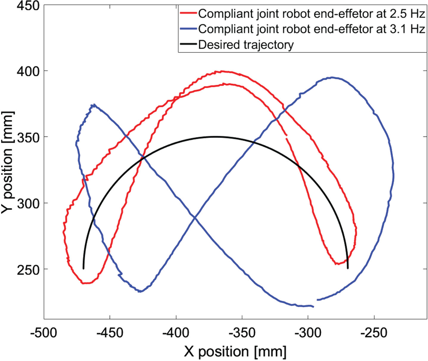
Position of the end-effector of the compliant joints robot in a task at 2.5 Hz and 3.1 Hz.
The frequencies where the changes in the trajectory start are 2.5 Hz and 3.1 Hz.
The compliant joint robot operated normally at low control frequencies, following the trajectory with the RMSE of less than 15 mm such as 1 Hz and 1.2 Hz like in Figs. 5 and 6. However, as the frequency increased to 2.5 Hz, the end-effector starts a deviation from the desired trajectory by a RMSE of 300 mm. This deviation amplified further as the frequency rose 3.1 Hz as show in Fig. 8, with end-effector errors increasing to 350 mm. When the compliant joint robot reaches the control frequency of 3.1 Hz the experiment is stopped due to vibrations on the base of the robot.
In order to give meaning to this behavior of the robot at these frequencies it was done an impulse response of the compliant robot. This experiment shows that the behavior at 1.25 Hz, 2.5 Hz and 3.1 Hz correspond to peaks in frequency of the impulse response. In Fig. 9 it is shown the impulse response. The peaks correspond to vibration modes of the compliant robot.
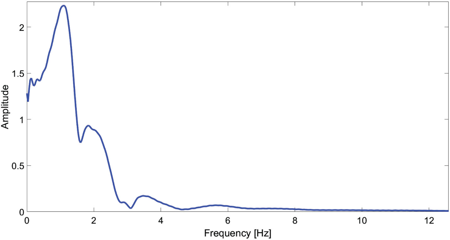
Impulse response flexible robot.
The compliant robot exhibited larger errors at 1.25 Hz, 2.5 Hz, and 3.1 Hz because these match its vibration mode frequencies. At these natural frequencies, the vibrations of the compliant joints and links become amplified by resonance. The feedback control system is unable to attenuate the resonant vibrations, leading to larger positioning errors. This demonstrates a potential drawback of compliant robots which reduce positional accuracy. Potential solutions include changing the joint stiffness to shift the resonances, implementing vibration isolation, or using resonance damping techniques. Further testing could map out the frequency response more fully to characterize the resonant behavior and quantify the impact on accuracy.
This paper presents a data-driven control approach using a Feedforward Neural Network module to achieve precise trajectory tracking for a five-bar robot with compliant joints. The compliant joints introduce uncertainties that make model-based control difficult, so a model-less technique was implemented. The Neural Network identified the inverse dynamics of the system for input to a coordination of Feedforward control method. Experiments demonstrated the approach enabling the compliant robot to perform pick-and-place tasks up to 1.25 Hz with low error. In contrast, a comparable bearing-joint robot showed rapidly increasing errors above 1 Hz. This highlights the benefit of the adaptive data-driven controller in managing the complex flexible dynamics.
The results validate the proposed control framework for low-error tracking of flexible parallel robots without relying on analytical models. This provides a practical solution for control of compliant mechanism robots where modeling is challenging.