
Abstract
In recent years, the use of Gas Turbines (GTs) to generate electricity has grown exponentially. Therefore, for the optimal performance of gas power plants, a lot of research has been done on modeling different parts of GTs, estimating model parameters, and controlling them. But most of the available methods are not accurate enough, like most linear methods, or are model-based, which require an accurate model of the system (like most nonlinear methods), or there is a constant need to adjust the controller parameters. To address these shortcomings, this study uses a new hybrid method including the brain emotional learning-based intelligent controller, the nonlinear multivariate method in the form of feedback linearization, and an adaptive control method of mode predictive reference model used to quickly control the GT. The Rowen model is used to simulate the nonlinear model of the GT. Owing to the influence of exhaust temperature on the speed of GT and the multivariate system model, nonlinear multivariate controller design is considered. First, the adaptive control method of the state-predictive reference model for a multi-output multi-input system, in general, is presented, and then, the proposed method for a GT with real dynamic values is implemented. The simulation results show the ability of the proposed controller to control the GT. In order to prove the efficiency of the proposed method, the obtained results are compared with the PID industrial controller method and the classical reference model method.
Keywords
Nomenclature
Gas Turbine
Brain Emotional Learning-Based Intelligent Controller
Proportional– Integral– Derivative
Improved Input and Output Self-Tuning Hybrid Modeling
Inlet Guide Vanes
rotor speed
mass flow of fuel
Pressure of GT
Temperature of GT
optimum temperature
Function of the opening of the inlet air valve to the compressor
Position of IGV
Mass flow rate of fluid and smoke passing through the turbine
Mass flow rate of throttle
Mass flow rate of blow off
Mass flow rate of compressor
Pressure at compressor
Pressure at plenum
Pressure at turbine
Temperature of compressor
Temperature of plenum
Temperature of turbine
Inner temperature of the system
Volume of compressor
Volume of plenum
Volume of combustion chamber
Area of compressor
Temperature dependent constants
Inertia
Efficiency
Position of fuel valve
Position of blow-off valve
Inlet index
Outlet index
Output node in the structure of the amygdala
Output node in orbital cortex networks
Nodes weight
Sensory inputs
Desired amount of output
Output errors
Introduction
Literature review
Till now, various methods have been proposed to control Gas Turbines (GTs). Regarding the control of GTs by classical methods, several cases could be mentioned. A turbojet engine controller for unmanned aircraft using Fuzzy-PI [1] and Fuzzy-PID [2] is proposed. In [3], a new control technique has been proposed based on the hybridization of the improved Particle Swarm Optimization (PSO) algorithm and cuckoo search algorithm to tune the fuzzy PID controller parameters for optimal control of a micro GT. In [4], novel nonlinear and linear active disturbance rejection controllers and a PID controller have been designed for a micro GT and the results are validated with the experiment set. Imani and Montazeri-Gh [5] have proposed a new controller model based on the Min-Max algorithm for optimal control of aircraft GT engines. The robust method as H ∞ output feedback and the distributed control architecture has been used in [6] for GT control. In [7], a sliding mode model-based control for GT is proposed. In [8], a frequency control strategy is proposed for an island power system with increasing the proportions of GTs. Other research [9–12] in the last decade has proposed an optimal control method of GT.
In [13], authors have considered the nonlinear models of the GT, and have controlled it with hybrid neural networks and genetic algorithms. In [14], a novel integrated control method is proposed by combining the original controller with a new neural network controller to improve the performance of the original controller of an aero-derivative GT. In [15], a fast model predictive control algorithm is proposed for high control performance, and a modeling method combined with entropy clustering with subspace identification is adopted. The proposed modeling and control methods are easy to put into practice, and the high modeling precision and excellent regulating speed of the Fast-MPC are verified. In [16], a novel GT performance system is presented for representing the nonlinear behavior of a two-shaft GT engine. In [17], a physics-based mathematical model of a mini SR-30 GT engine is presented using a state variable modeling method. This model is developed by utilizing approximated maps of the engine components and generic governing equations that describe the engine’s behavior. In [18], an Improved Input and Output Self-Tuning Hybrid Modeling (IOSTHM) method is proposed for improving the GPM modeling accuracy of a dual shaft turbofan GTE. The proposed IOSTHM consists of an input self-tuning model (ISTM) and an Output Self-Tuning Model (OSTM). In [19], self-enhancing loops for active transient protection and thrust response improvement of GT aero-engines are established with periodically updated control parameters. In [20], the conflict between gas turbine thermal efficiency enhancement and NOx emission reduction is discovered and analyzed with a nonlinear model. For this aim, the multi-objective genetic algorithm is proposed and solved under various scenarios. In [21], the Modelica description method is used for GT control. The results show the robustness of the proposed method.
The Brain Emotional Learning Based Intelligent Controller (BELBIC) is one of the robust control and optimization methods that is used in several applications [22–28]. The main application of this method is controlling various systems.
Research gap and motivation
Nowadays, GTs are abundantly employed in the industry. A GT is defined as a rotating machine that works based on the generated energy of the combustion gases. The characteristics of the GT are environmental compatibility and less impact on the degradation and production of greenhouse gases compared to other power generation systems on an equal scale [29]. GTs can be used in several different modes in important industries such as power plants, oil/gas industries, processing plants, and aviation, as well as domestic industries and smaller related industries [30]. An important disadvantage of these systems is their low efficiency that is because of the high energy losses from the exhaust [31–33]. These gases could be utilized in the steam turbines to enhance the system’s efficiency. The GT system has two inputs and two outputs, the inputs of which are the fuel flow and the propulsion angle at the impeller (air valve), and the system outputs are the engine airflow and the axial pressure. Also, two system mode variables include the speed of the two turbines.
The GTs consist of various parts as follows: 1) the compressor for air condensation, 2) a combustion chamber for combining the fuel and air, then igniting the result, 3) a turbine for transmuting the energy of hot and gas to mechanic power [2–4]. A part of this generated power is spent on compressor spinning, and the rest depending on the application, is used for different usages (turbo-generator, turbo-fan, turbo-jet, etc.) [6].
The output power of GTs is mainly controlled by adjusting the amount of fuel burned in the combustion chamber [12]. Excess and uncontrolled fuel can cause the turbine to overheat and increase its speed too much, which can eventually lead to serious engine damage. Therefore, an engine control system should be considered [15]. Of course, this engine control system should not hurt turbine performance. Today’s control systems are quite complex, especially for DLE GTs. These systems are designed to determine the appropriate ratio between fuel and air, the emission of toxic gases and pollutants NOx UHC and CO to the permissible level [20, 21].
Classical controlling methods are mostly based on system exploration and modeling [34–36]. As these systems become more complex, identifying them with previous methods becomes difficult or impossible. Due to the dynamics of the controlled system, the occurrence of uncertainty, and even the change of the system due to wear and tear, there is a need to design and readjust the controller [37]. Therefore, there is a need for new methods that do not have problems in design and implementation. Resetting controller parameters is a time-consuming task in itself. Even for controllers that are not dependent on the model, such as fuzzy controllers, there is a need for automatic or manual adjustment of parameters. Therefore, adaptive as well as intelligent control are novel solutions to control engineering.
The paper contributions
In this paper, a robust hybrid control method, based on the Brain Emotional Learning Based Intelligent Controller (BELBIC), the nonlinear multivariate method in the form of feedback linearization, and an adaptive control method of mode predictive reference model is used to quickly control the GT. In addition, for modeling the GT, we used the Rowen model to consider the nonlinear behavior of the GT. The results are compared with the PID controller to present the advantages of the proposed method. In essence, the contributions of this paper could be listed as follows: Using a hybrid method based on BELBIC– a multivariate controller based on the adaptive method, and tracking the reference mode of GT, that won’t be considered before; The multi-input (positions of the control valves) and multi-output (temperature and speed of GT) are considered; A robust model based on the modified Rowen method is employed to simulate the GT; The proposed controller is faster and contains lower disturbances than other compared methods.
Paper organization
The rest of the paper is as follows: in Section 2, the Rowen model is presented to model the nonlinear performance of GT, in Section 3, BELBIC method is described, Section 4 introduce the multivariate controller, in Section 5, the results are rendered, and Section 6 is the conclusion if the results.
Rowen GT model
The block diagram of a sample GT is shown in Fig. 1. The basis of a GT is an air compressor, a combustion chamber, and a turbine, which are arranged in series and series. First, the inlet air is compressed and then it enters the combustion chamber, which increases the pressure and temperature of the air (gas) due to the combustion mechanism together with the fuel. The gas then expands in a turbine, causing it to spin. The turbine rotates the compressor and its excess energy appears as a thrust reaction or mechanical force and a combination of the two at the end of the output shaft [1].
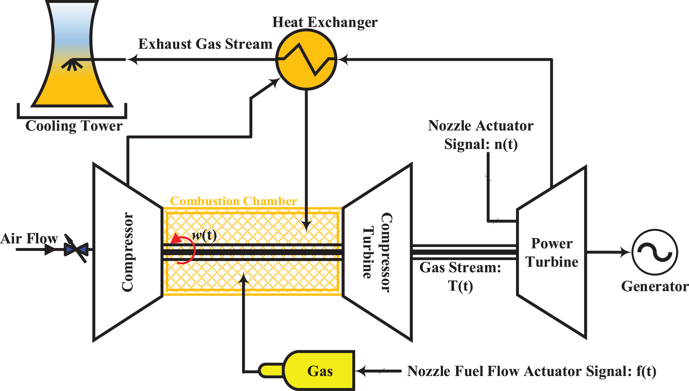
The components of a GT.
Each GT works on the same basis but with different variables. The number of stages or their arrangement can change, but always the stages of combustion pressure increase (heating), and finally the expansion of fluid (hot compressed air) in succession and in the same way in all turbines causes power generation. The Rowen model is the simplified mathematical model of a GT. This model can also be used to investigate the effect of the governor on system performance. This model is verified with real data and is suitable for checking the actual performance of the system. This model is shown in Fig. 2.
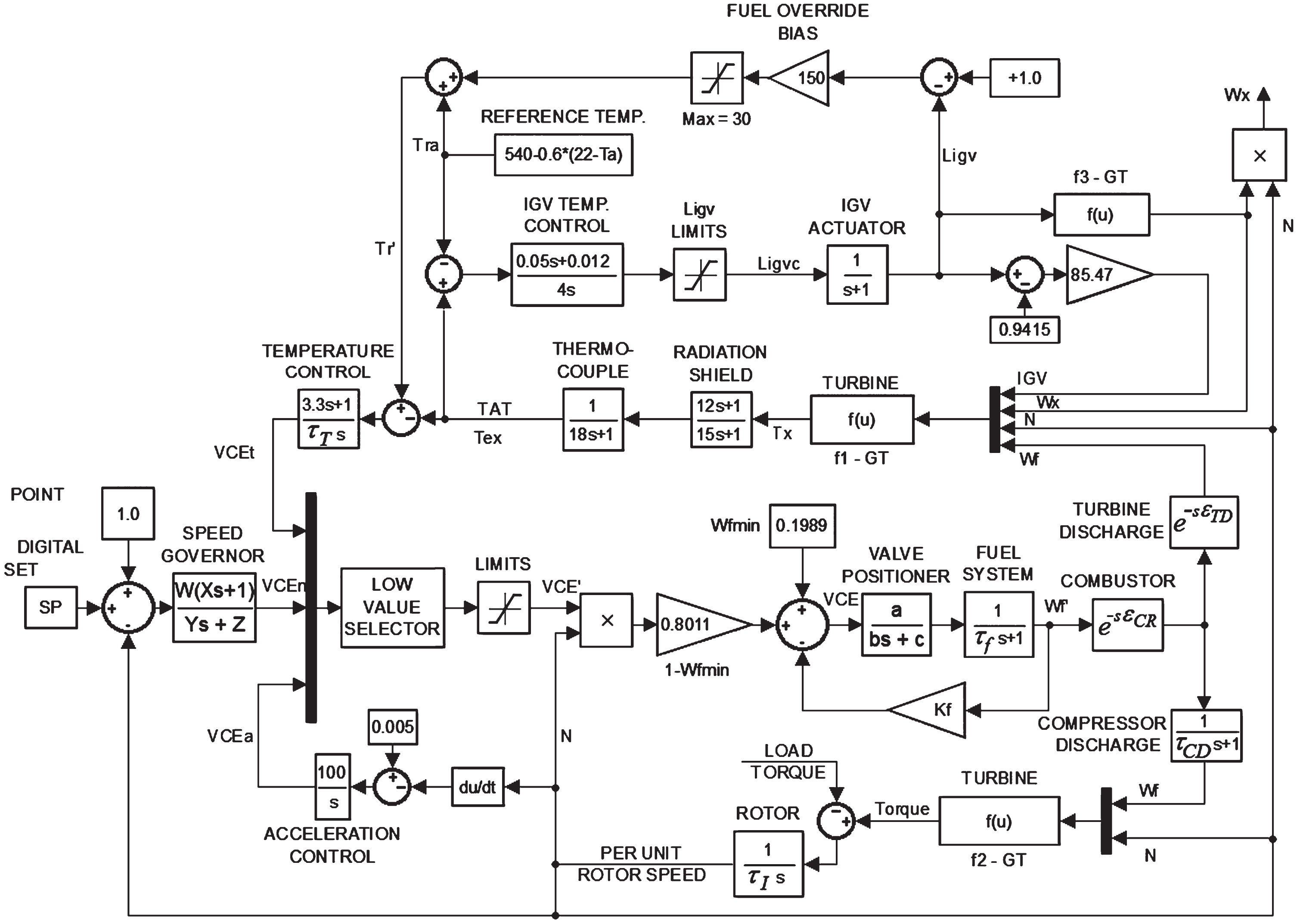
Modified Rowen model [2].
In this figure, K NL is the amount of fuel required to operate without producing a GT load, which is considered in the Rowen model. The compressor discharge block is to take into account the dynamics of the fuel injection until the temperature at the turbine inlet rises, which must be taken into account due to the large volume in the combustion chamber between the fuel injection nozzles to the turbine inlet [12]. The turbine characteristic in the Rowen model is provided by the function block f1, f2, and f3. Function f1 is used to calculate the exhaust gas temperature, function f2 is used to calculate the turbine torque, and function f3 is used to calculate the airflow through the turbine. These functions depend on the fuel flow, rotor speed, and inlet air temperature. The general form of the functions f1, f2 and f3 is given as follows [14–16]:
Based on the “survival and mass” law, the system state variables should be presented according to the pressure (p) and temperature (T) of GTs. The obtained equations are used according to an ideal gas, balancing the amount of passing volume, and homogeneity in various systems. However, in the novel models, different factors are added to the system equations, like as compressor efficiency, expansion tank, and the uncertainties related to the chamber [12]. So, by providing an equilibrium between the generation and consumption energies of a GT, a difference nonlinear equation will be obtained for its speed (N). The inputs could be considered as the amount of fuel flow and variation of the blow-off valve, and the outputs could be assumed as the temperature of the inlet GT and the rotation speed of the GT shaft. The nonlinear relations for a sample GT could be reformed as follows [11–17]:
As defined in the above equations, a model with 7 state variables. In this model, we assumed 2 inputs that includes the position of fuel and blow-off valves, and 2 outputs for the system that consists of inlet temperature of GT and rotation speed of the GT shaft [19].
Emotion is one of the factors that has recently entered the field of Artificial Intelligence (AI), inspired by biological systems as an important factor in decision-making. The BELBIC is an outstanding example of this AI. It has been first introduced in 2004 [22], and in recent years these controllers have been used with little modification for a variety of applications [22–28]. In [22], this control method is used to control the motor drive. In [23], it has been implemented in the engine system in a laboratory. In the BELBIC, the emotion factor as a negative factor is produced by the critic, and controller parameters that have a network structure are adjusted accordingly. This controller is based on the amygdala computational model [25]. The structure of the mentioned controller is shown in Fig. 3 [25]. The amygdala is the part of the brain that is responsible for emotional processing and communicates with the sensory layer. In Fig. 3, the amygdala and the orbitofrontal cortex in the computational model have a network structure, in each of which there is a node for each sensory input. In the amygdala, there is also a node for the entrance to the thalamus. The value of this input is equal to the maximum amount of sensory inputs. The output of nodes in the amygdala and orbitofrontal cortex is calculated as follows [28]:
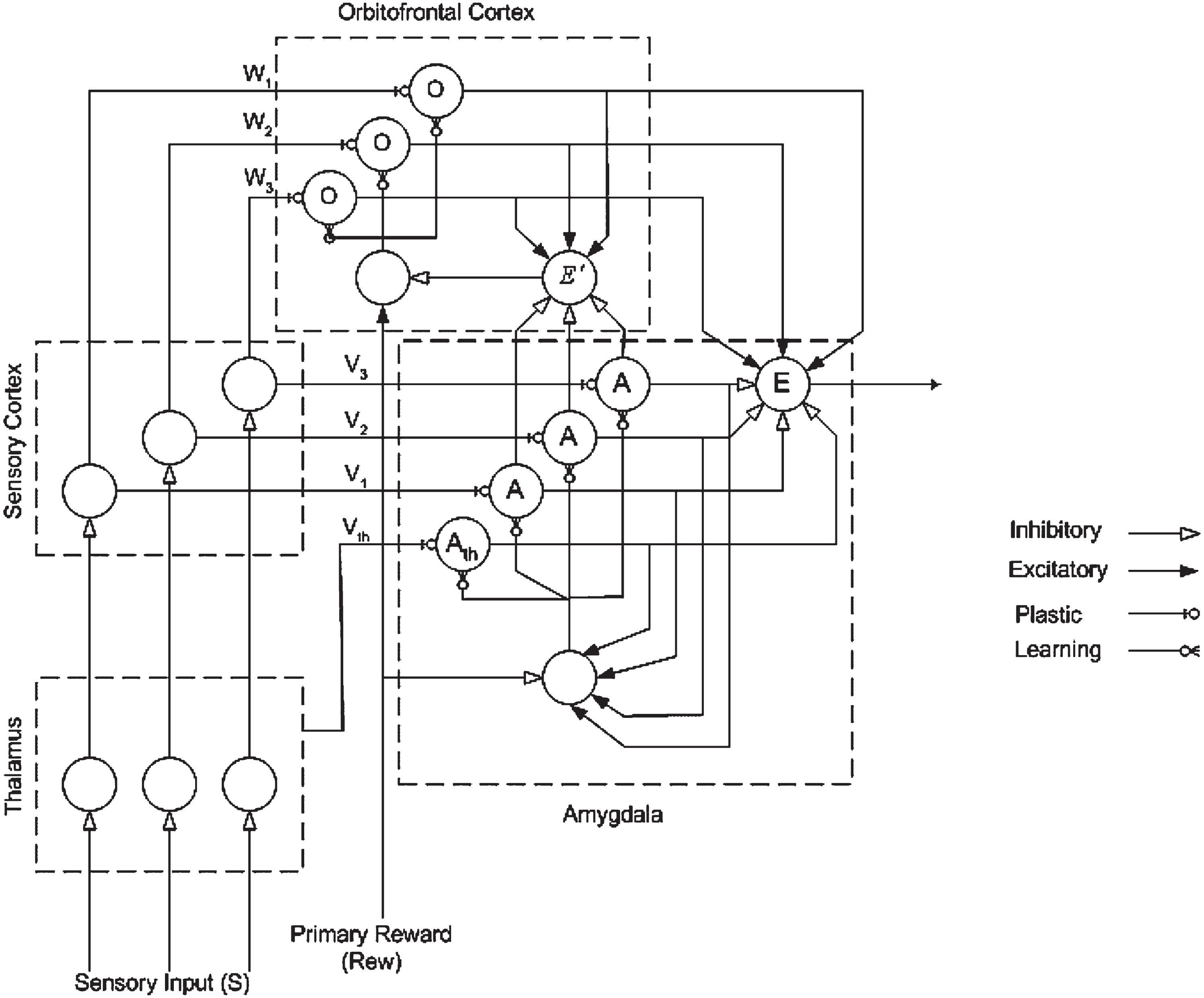
Computational model of the BELBIC [25].
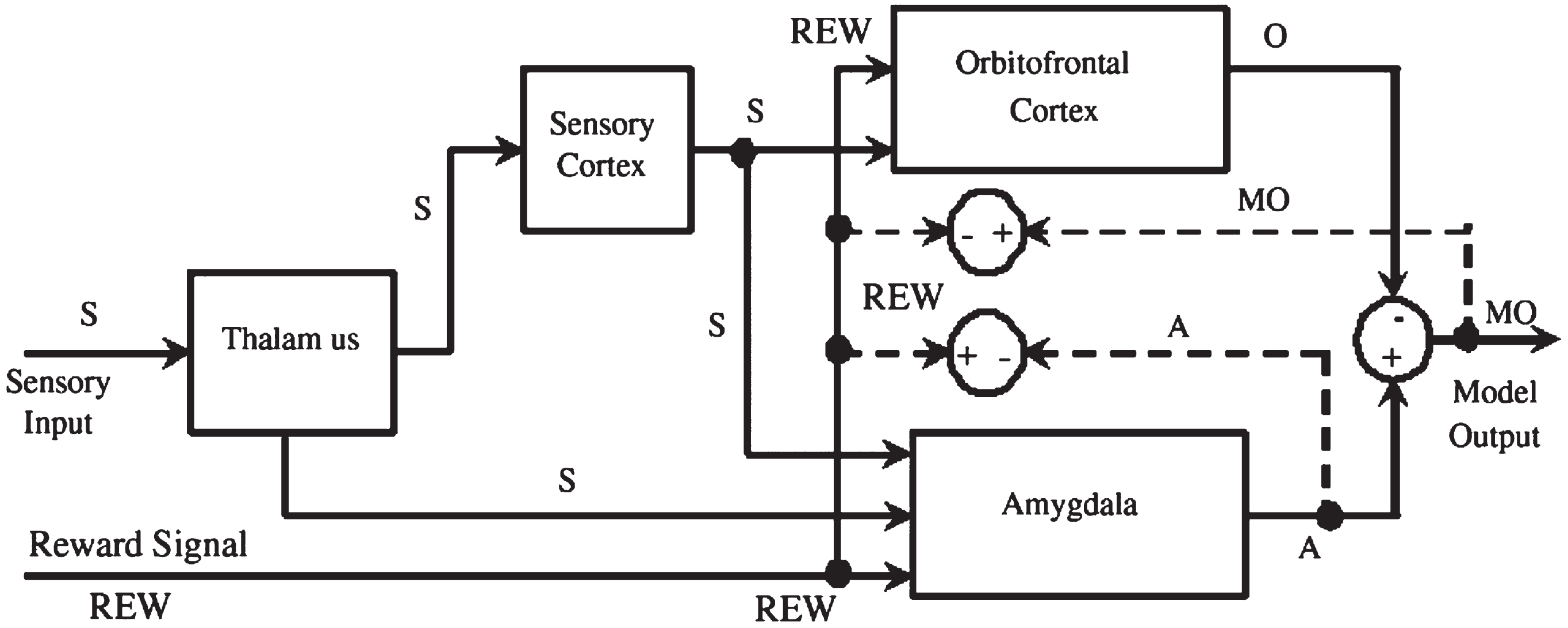
Block diagram of BELBIC method [24].
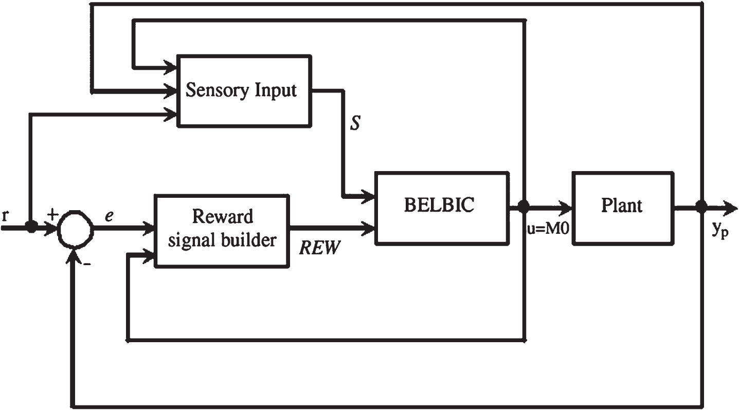
Control loop with BELBIC [26].
Fuel flow control is based on three criteria (control loop). According to Fig. 5, these three control loops are speed control, temperature control, and output acceleration control [21]. These three control systems are sent to the selection block of the minimum that selects the minimum value sent by the controllers. The turbine controls the inlet temperature of the turbine based on the exhaust gas temperature of the turbine, which is measured by a set of thermocouples. The acceleration control lever is used to prevent the generator from accelerating when the load is suddenly lifted. The speed controller shown in the model in Fig. 5, if zero derivative z is placed in the denominator, will become an integral control with the ability to eliminate the permanent error in the event of a drop in distance due to the increase in load in the network. Control is called synchronous application mode [27]. But in most cases, the production load of power plants in the event of perturbation will only increase definitively and then return to the set value, in which case the denominator of the fraction will be an integral form of the first-degree polynomial and the power plant Until the network reaches the nominal speed, it will produce more load in proportion to the amount of difference and will then return to normal load generation.
The design method of nonlinear controller with feedback linearization method based on the system output is considered in this paper. In stabilization, the goal is obtaining a proper control law like u for a general nonlinear system as
Therefore, by determining the values of ki, in which all roots of (27) consist of a negative real part and provide proper performance of the system, the stabilization of the desired system could be carried out. The final model of the proposed controller is shown in Fig. 6. In this model, a reference model is considered, and with predictor, adaptive laws track the error in order to minimize it. Also, the GT model is simulated with the Rowen model, and the proposed multi-input multi-output nonlinear controller is employed.
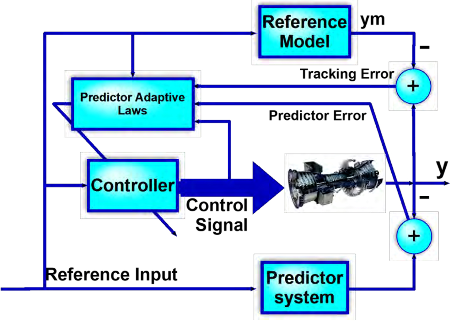
The proposed model for controlling the GT.
In this section, we considered two various cases as full-load and no-load conditions. The gains of the PID are considered as K p = 4, K i = 3.2, and K d = 2.5 [4]. The results are rendered in the following.
Full– load conditions
The performance of reference input tracking with the proposed method and PID controller is shown in Fig. 7. As seen in this figure, the proposed method is faster and lower fluctuations. In addition, the proposed method in high spool speed could reach to the second aim speed (0 m/s) without any fluctuation. Moreover, both method has delay to aim speeds about 2– 3 s. Figure 8 shows the two control inputs in the two methods. In the proposed method, both control inputs, i.e. fuel input and changing the angle of the locust, have much fewer fluctuations and in fact, the input is completely smoother than the PID method.
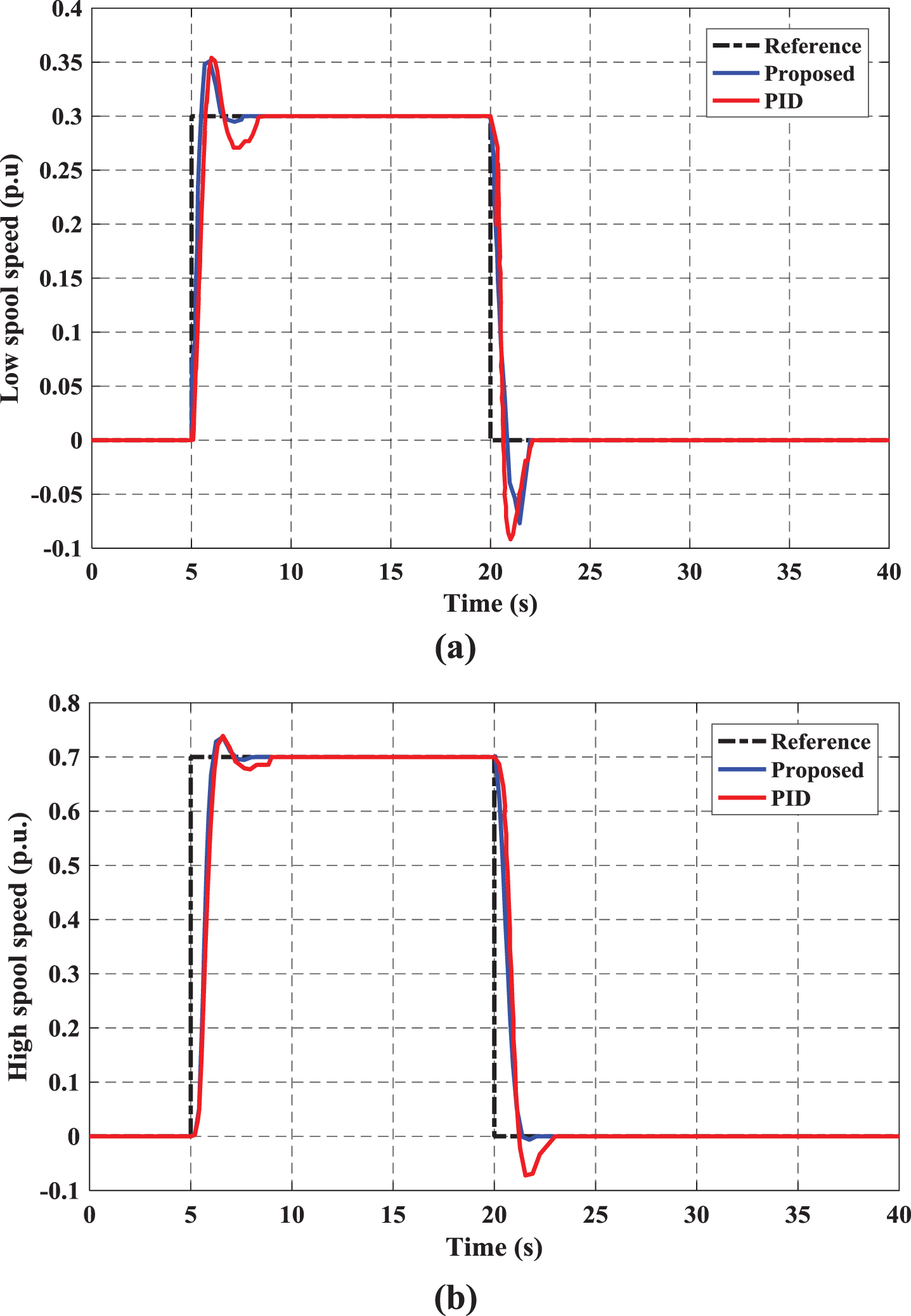
The performance of reference input tracking with two methods in full-load: a) the proposed method, b) PID.
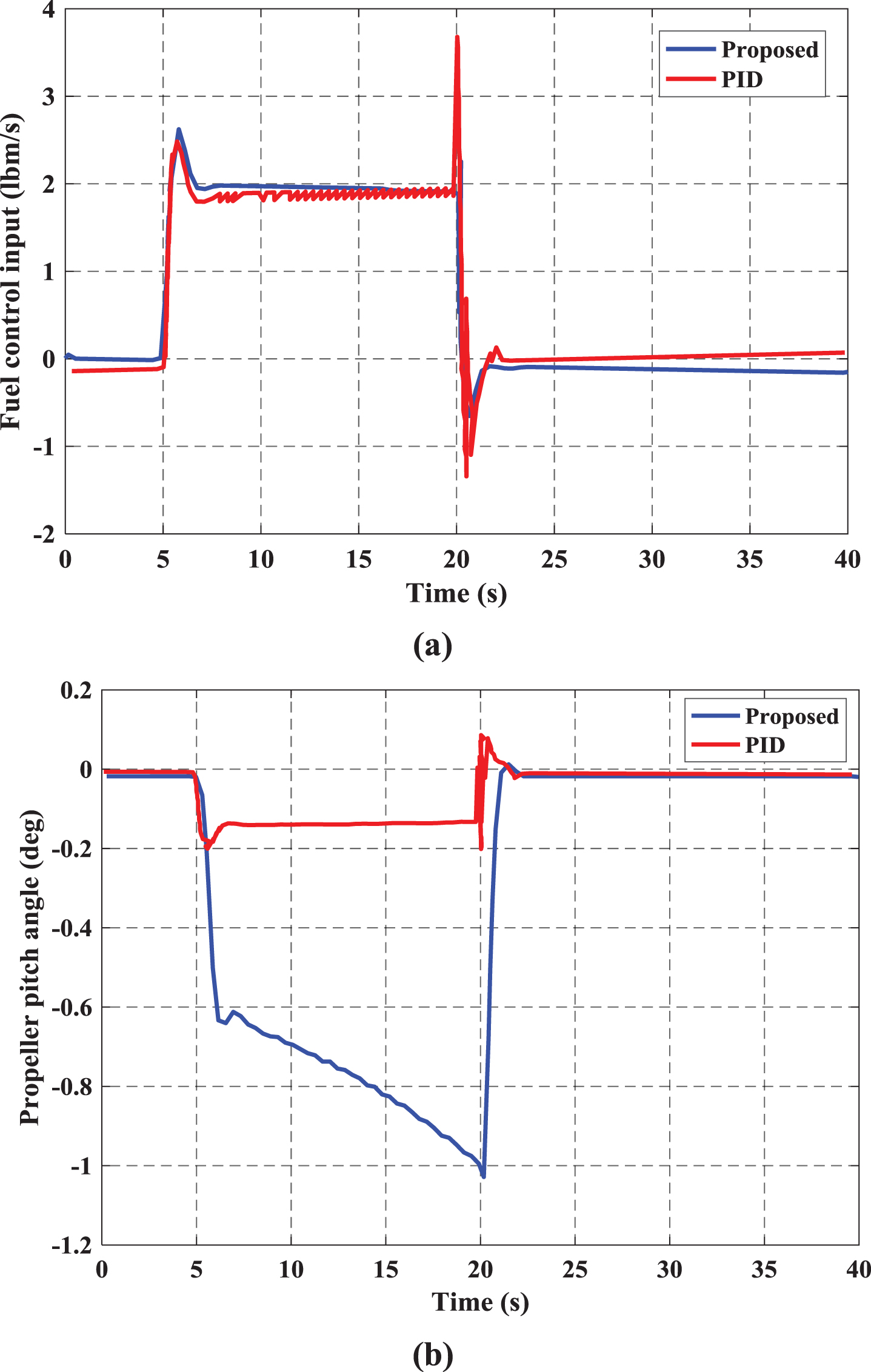
The input signals with two methods in full-load: a) the Fuel control input, b) the Propeller pitch angle.
According to Fig. 9, which shows the tracking error for two classes CET (E1) and LET (E2) in the both proposed method and PID, it could be seen that the proposed method has a favorable effect on control requests, eliminates unwanted fluctuations in the error tracking, and causes the output error to converge to zero sooner.
The tracking error with two methods in full-load: a) the proposed method, b) PID.
The main purpose of the control is speed control (turbine power). Figure 10 (a) shows the controlled torque output of the turbine applied to the generator. The torque is regulated to the amount required to produce the proper power. Figure 10 (b) shows the flow rate of the fuel consumed (proportional to the opening of the control valve). This signal represents the physical variable of the control signal. Another important parameter is the temperature of the turbine, which is shown in Fig. 10 (c). It can be seen that the internal temperature of the turbine is maintained at 950 °C. Finally, Fig. 10 (d) shows the rotation speed (rotor speed) of the generator, which is normalized to the value 1 that has converged. It could be seen that rotor speed after about 11 s, reach to the reference speed (1 p.u.).

Variation of the various parameters of GT in full load: a) torque, b) fuel flow, c) temperature, d) speed.
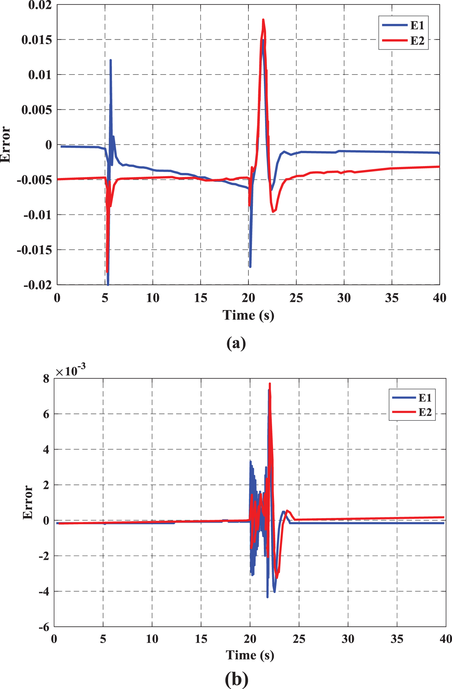
In this case, the minimum output power of the engine is considered. The performance of reference input tracking with the proposed method and PID controller is shown in Fig. 11. As seen in this figure, the tracking performance with the proposed method is so better than the PID method and reduces the initial fluctuations, especially in the axis with low speed. Figure 12 shows the two control inlets of the inlet fuel and the changes in impeller angle with two control methods. As seen in these figures, with the proposed method the controlled signal consists of a smaller amplitude than PID. The tracking error for two classes CET (E1) and LET (E2) with the proposed method and PID controller is shown in Fig. 13. Although the proposed method provides an error slightly larger than the PID, it has much less fluctuation.

The performance of reference input tracking with two methods in no-load: a) the proposed method, b) PID.

The input signals with two methods in no-load: a) the Fuel control input, b) the Propeller pitch angle.

The tracking error with two methods in no-load: a) the proposed method, b) PID.
Finally, the summarized table of comparing the results of various methods under no-load condition are shown in Table 1. As shown in this table, the proposed method has better results in comparison with other methods based on PID. The important parameter in this problem in the propeller pitch angle that the proposed method could control it with the lowest distortion.
The summarized results under no-load condition
In this paper, a novel control method is introduced and used for optimal control of Gas Turbine (GT) in various conditions. The multivariate feedback linearization method with a combination of the Brain Emotional Learning Based Intelligent Controller method to control the speed and temperature of a GT is proposed. In addition, the Rowen model was used to simulate the nonlinear model of gas. To show the system performance, the results were compared with the PID industrial control method. In order to show the efficiency of the proposed model, the studied GT in two modes of full load and no load is studied and their results are presented. The results show that the proposed method includes higher speed (about 30 %), a lower range of oscillations (about 24 %), and more favorable convergence than the PID industrial controller method. In addition, the error tracking curves of PID are lower than the proposed method but contain more fluctuations (about 4 s longer).
In future work, we could present other control methods for controlling the GT based on its various conditions as faults.