
Abstract
Gas gathering pipeline network system is an important process facility for gas field production, which is responsible for collecting, transporting and purifying natural gas produced by wells. In this paper, an optimization model for the layout of star-tree gas gathering pipeline network in discrete space is established to find the most economical design scheme. The decision variables include valve set position, station position and pipeline connection relation. A series of equality and inequality constraints are developed, including node flow balance constraints, pipeline hydraulic constraints and pipeline structure constraints. A global optimization strategy is proposed and an improved genetic algorithm is used to solve the model. To verify the validity of the proposed method, the optimization model is applied to a coalbed methane field gathering pipeline network in China. The results show that the global optimization scheme saves 1489.74×104 RMB (26.36%) in investment cost compared with the original scheme. In addition, the comparison between the global and hierarchical optimization scheme shows that the investment cost of the global optimization scheme is 567.22×10⁴ RMB less than that of the hierarchical optimization scheme, which further proves the superiority of the global optimization method. Finally, the study of this paper can provide theoretical guidance for the design and planning of gas field gathering pipeline network.
Introduction
Background
In the continuous development of world energy, the proportion of global natural gas consumption in primary energy consumption is increasing. Today, the use of natural gas is close to a quarter of the world’s energy demand, and the proportion is expected to rise from 23% to 30% in 2050, surpassing oil to become the largest energy source around 2045 [1]. The development and utilization of natural gas is not only the trend of energy development in the world, but also an important productive force for social development [2]. In the process of exploration and development of gas fields, with the deepening of the development of unconventional gas fields such as coalbed methane and shale gas, the surface environment of newly discovered gas field blocks has become more and more severe, and the complexity of the gathering pipeline network has also increased sharply. Usually, the investment cost of the gathering pipeline network system can account for 50% to 70% of the surface engineering of the gas field [3]. Therefore, in the process of pipeline network design, using intelligent optimization technology to reasonably design the topology structure and process parameters of the pipeline network can obtain huge economic benefits.
The gas gathering pipeline network system mainly includes wells, valve sets, stations and surface pipelines, as shown in Fig. 1. According to different functions and sizes, surface pipelines are divided into production pipelines and gathering pipelines. The natural gas produced from the reservoir first enters the production pipeline through the well, and the production pipeline collects the untreated natural gas to the valve set. Then the natural gas is transported to the central station by the gas gathering pipeline for purification treatment to meet the requirements of external transportation. The basic topological structure of gas gathering pipeline network mainly includes three types: star topology, tree topology and cyclic topology. However, in the process of actual gas field development and construction, it is difficult for a single network structure to meet the requirements of the natural gas gathering process. Engineers often use pipeline network structures that combine multiple topological forms. The common combined pipeline network structure mainly includes star-star topology, cyclic-star topology and star-tree topology. The star-tree combined pipeline network structure means that the first-level production pipeline between the well and the valve set is in a star topology, and the second-level gathering pipeline between the valve set and the station is in a tree topology. Figure 1 shows a typical star-tree pipeline network structure. Because the star-tree pipeline network structure is widely used in gas field development and difficult to design, the research in this paper will focus on this type of pipeline network.
Schematic diagram of gas gathering pipeline network.
The optimization problem of the layout design of the gas gathering pipeline network refers to the formation of an optimal layout scheme that meets the technological requirements under the premise of knowing the location distribution of each well. The optimization problem covers several sub-problems, including the well group division, determining valve set and station positions, and determine pipeline connection relationships between facilities (Fig. 2). According to the different selection methods of valve set and station, the problem can be divided into continuous space optimization and discrete space optimization. Continuous space optimization means that the facility location can be arbitrarily selected within the gas field area, while discrete space optimization means that the facility location can only be selected at the location of the existing wells (the facility is expanded at the well). This paper mainly studies the optimization problem of pipeline network layout in discrete space. Besides, in the entire pipeline network layout optimization model, there are binary variables representing the facility location and pipeline connection relationship, as well as nonlinear constraints such as pipeline hydraulic equation. Thus, this problem belongs to a typical Mixed Integer Nonlinear Programming (MINLP) problem and is difficult to solve. Therefore, this paper aims to propose an effective solution method to solve the layout optimization problem of star-tree gas gathering pipeline network in discrete space.

Optimization process of gas pipeline network layout.
At present, many scholars have carried out relevant research on the optimization of gas pipeline network layout and have achieved certain research results. According to the difference of constraint conditions, the optimization mathematical models are mainly divided into Mixed Integer Linear Programming (MILP) model and MINLP model. Zhang et al. [4] established a MILP model for the construction of the gathering pipeline network in offshore oilfields, considering the constraints of gathering scope, economic flow and terrain obstacles. Adasme [5] proposed a MILP model to solve the P-median problem constrained by cyclic, tree, and star topologies in facility siting. Zhou et al. [6] proposed a MINLP model aiming at maximizing the total benefit of water injection development for the optimal water injection strategy and surface water injection network operation control scheme. He et al. [7] proposed two MINLP models, including optimization of pipeline network topology and optimization of pipeline paths under 3D terrain. Zhou et al. [8] established a MINLP model considering constraints such as flow conditions, inter-well relationships, and the number of stations for gas storage injection and production.
In terms of the research method of solving the layout optimization model of gas pipeline network, it is mainly divided into the study of optimization strategy and optimization algorithm. The optimization strategy can be divided into hierarchical optimization strategy and global optimization strategy. The main difference between the two is whether to solve multiple sub-problems in stages and in turn, or to solve them as a whole. The hierarchical optimization strategy can quickly obtain optimization results, but the results may only be local optimal solutions. On the contrary, the global optimization strategy has high computational cost, but it can ensure the global optimality of the solution. For mathematical problems with high precision and complex models, optimization methods based on surrogate models can be considered in the global optimization [9, 10]. This method can improve the efficiency of global optimization and reduce the computational cost of the algorithm. After determining the solution strategy, an effective solution algorithm is selected to solve the optimization problem to obtain the optimal pipeline network layout scheme.
Liu et al. [11] proposed a hierarchical optimization strategy to optimize the layout of the multi-level star topology oil and gas gathering pipeline network, and used the K-Means clustering algorithm and the improved particle swarm algorithm to optimize the solution. Wei et al. [12] proposed a hybrid optimization solution strategy including multiple layers, punishment function and intelligent optimization algorithm for topology and parameter optimization of surface pipeline network. Ren et al. [13] used a hierarchical optimization strategy to divide the optimization problem into multiple sub-problems to solve the shale gas surface gathering system. Zhou et al. [14] adopted a layered optimization strategy for the construction of tree topology surface gathering pipeline network in gas fields, and proposed an optimization solution program based on Delaunay triangulation. Zhang et al. [15] established a general MILP model considering terrain and obstacle conditions, and solved it with an global optimization strategy, which can simultaneously obtain the optimal topology of the pipeline, the location of the central processing facility and the diameter of the pipeline. Hong et al. [16] established a comprehensive MILP model for the gathering network, based on the global optimization strategy, and used the Cplex solver to solve the model.
Contributions
Based on the review of relevant literature in the field of gas pipeline network layout optimization, it is found that scholars have carried out a lot of research work in the establishment of mathematical models, and the development of solution strategies and solution algorithms. However, most of the pipeline network structures studied are mainly single pipeline network topologies, and less consideration is given to multi-type combined pipeline network structures. Most of the optimization models established are MILP models, which often ignore the nonlinear constraints of pipeline hydraulic characteristics. Besides, in order to reduce the difficulty of solving, the solution strategy is also mainly based on hierarchical optimization strategy, and it is difficult to ensure the global optimality of the solution. Based on this, this paper establishes a MINLP model for the layout optimization of star-tree gas gathering pipeline network, and a global optimization solution strategy is proposed to solve this optimization model. The main contributions of this article are as follows: A MINLP optimization model for the layout of star-tree gas gathering pipeline network in discrete space is established to minimize the system investment cost. A global optimization solution strategy is proposed, which can simultaneously decide well group division, valve set and station location, and pipeline network connection relationship. An improved genetic algorithm (GA) is developed to solve the model, and the pipeline hydraulic and diameter iterative calculation are combined in the algorithm.
Paper organization
The rest of the paper is structured as follows. Section 2 defines the objective function and constraint conditions of the mathematical model. Section 3 proposes a global optimization framework and an improved GA algorithm. Section 4 introduces the basic conditions of the practical gas gathering pipeline network case. Section 5 discusses the optimization results. Finally, Section 6 summarizes the whole paper.
Mathematical model
To facilitate modeling and analysis, define sets: (1) The set of well is defined as I, where i∈ I = { 1, 2, …, N I }, N I is the elements number of I. (2) The set of valve set is defined as J, where j∈ J = { 1, 2, …, N J }, N J is the elements number of J. (3) The set of station is defined as K, where k∈ K = { 1, 2, …, N K }, N K is the elements number of K. The relationship between the three sets is K ∈ J ∈ I. It should be pointed out that the flow direction of the valve set should be determined when the tree structure is used to connect the valve set with the station. Therefore, a variable j′ is added to represent the number of the next valve set or station of the flow direction of valve set j.
Objective function
The objective function of this model is to minimize the total investment cost of gas gathering pipeline network. Investment costs mainly include valve set investment cost (F
v
), station investment cost (F
c
), star topology production pipeline investment cost(Fp,S) and tree topology gathering pipeline investment cost (Fp,T). The objective function is shown in Equation (1).
Node flow balance constraints
For the valve set, there are multiple production pipelines connected to it, and the node flow balance equation at the valve set is shown in Equation (6):
When the valve set is connected with the valve set/station in a tree-topology pipeline network, let the fluid flow from the valve set j to the valve set j′, and the node flow balance equation at the valve set j′ is shown as follows:
For the station, its node flow is the flow sum of all connected wells, as shown in Equation (8):
In the pipeline network, along the gas flow direction, the flow of each node should be greater than that of the upper node, as shown in Equation (9). The flow of each node should be less than the maximum flow passing capacity at the node, as shown in Equation (10).
The number of wells connected to the same valve set must be smaller than the maximum interface number of the valve set, as shown in Equation (11).
For the connection relationship between wells and valve sets, it is necessary to ensure that all wells are connected to a specific valve set, and that each well is connected to only one valve set. The constraint equation is as follows:
Similarly, it is necessary to ensure the existence of downstream nodes of all valve sets in the connection relationship between valve sets and station.
When gas flows in the pipeline, there will be pressure drop loss, and the fluid pressure drop formula can be used to calculate the pressure of each node in the pipeline [17]. In nonlinear condition, the pressure drop relation is determined by connection relation. For gas flowing from node i to node j, a
ij
= 1, otherwise a
ij
= 0. The equation of the pressure drop relationship between node i to node j is as follows:
The gas flow in the pipeline needs to be maintained by pressure drop, and the pressure of each node needs to be limited, as shown in Equation (17).
In order to ensure that the fluid is transported from the wellhead to the station within the allowable pressure drop, the gathering radius constraint should be considered. Gathering radius represents the maximum allowable length of pipeline from the well to the station, as shown in Equation (18).
For any well, according to Equations (15 and 16), the maximum length of pipeline that can be connected to the station under ideal conditions is that the well is directly connected to the station, and the maximum gathering radius is shown below:
For the tree-topology gathering pipeline network, the difference of network connection will result in the difference of the actual gathering radius of a single well. Therefore, the determination of gathering radius is a problem that changes dynamically with the change of the connection state of tree-topology pipeline network. In addition, for unconventional gas fields, the pressure drop between well and valve set can be ignored due to the low gas production from a single well. On this premise, the gathering radius of single well can be simplified as the gathering radius of valve set:
When calculating the investment cost of pipeline network, the pipe diameter, wall thickness and other pipe structure parameters should be considered, and the optimization calculation of pipeline network structure parameters should be carried out by cyclic iteration. The calculation equation of pipeline diameter is as follows:
The calculation of pipeline strength is the key to determine the thickness of pipeline wall. The thickness of pipe wall is calculated according to the circumferential stress, and then the strength is checked with the equivalent stress of the combination of circumferential stress and axial stress not greater than 90% of the minimum yield strength of pipe [18]. The wall thickness calculation formula is as follows:
In this paper, we choose the improved GA for the global optimization solution of the star-tree gas pipeline network [19]. The solution process is shown in Fig. 3. After the preliminary random well group division, the valve set/station was selected, and the pipeline cost between well groups was obtained iteratively after the primary pipeline diameter was determined by economic flow rate. Then the solution of the tree topology pipeline network connection is carried out. In the process of the tree topology connection, the hydraulic calculation is updated when passing through each node to ensure that the conveyable range is obtained each time. When the gas delivery pressure is insufficient, the comparative optimal solution is adopted. Respectively, the 2-opts algorithm reselects the connection of the pipeline network and the iterative solution method for adjusting the pipeline diameter. By comparing the construction cost of the two methods, the most economic connection scheme of the tree topology pipeline network is obtained. The optimal scheme optimises the tree topology pipeline network while considering the star topology layout.

Flowchart of the global optimization solution algorithm.
First, all wells are divided into well groups, and the layout of the first-level star topology pipeline network is determined. After the first-level layout structure of the pipeline network is determined, the divided well groups are simplified into valve set scattered nodes. The gas transmission volume of each well group is summed up to the valve set to obtain the set of valve set. We put the redundant well position numbers into the sub-nodes of each corresponding valve set to simplify the process of solving the tree topology pipeline network by reducing the number of tree topology nodes. At the same time, since the information of the sub-nodes in the valve set is preserved in the operation of the genetic operator, it provides the possibility for the valve set adjustment of the tree topology pipeline network.
Calculate the critical distance (farthest) valve set for the maximum gathering radius L max , and confirm the number of stations according to L max . There are three types of divisions.
(1) Case 1: The number of stations confirmed according to the L max of the four most remote valve sets is greater than or equal to 1, as shown in Fig. 4(a).
Regional division of station: (a) Case 1; (b) Case 2; (c) Case 3.
Let the common valve set included in the gathering radius of the four critical distance valve sets be U0, the intersection. In this case, the location of the station is selected from the intersection U0, and the site with the lowest total investment cost is selected as the location of the station according to the design result of the tree topology layout.
(2) Case 2: The number of stations confirmed according to the L max of the four critical distance valve sets is 0, but there are other wells in the intersection, as shown in Fig. 4(b).
In this case, it is necessary to re-divide the valve sets to which the wells in the intersection belong, and redefine the positions of the valve sets. Taking all wells in the intersection as candidate nodes, select nodes from the candidate set as gas station. Moreover during the genetic operation, to ensure the reliability of gas flow in the pipeline network, the genetic operation related to this node can only be cross-mutated from the intersection to prevent the occurrence of insufficient pressure.
(3) Case 3: The number of stations confirmed according to the L max of the four critical distance valve sets is 0, and there are no other wells in the intersection, as shown in Fig. 4(c).
In this case, the number of stations needs to be increased. Then the minimum number of stations required is determined by the L max of all valve sets. According to the actual situation, it is divided into several station areas, and each area is solved and designed. Finally, connect the valve set and determine the location range of the station.
In the global solution method, both pipeline and facility investment needs to be considered. The pipeline diameter will impact the layout structure and pipeline investment. Therefore, it is necessary to carry out hydraulic calculations while generating the connection relationship between facilities to ensure gas transmission feasibility and update each node’s pressure. The global optimization design embedded the hydraulic calculation in each node connection. At the same time, as the individual generation of the genetic algorithm (GA) is performed, the calculation and solution of the pipeline structure parameters and the update of the node pressure are carried out. In addition, the influence of the pipeline network structure on the optimal cost cannot be considered in the hydraulic calculation by iterative pipeline diameter. Therefore, in the tree topology connection, parallel optimization is adopted to design the connection of pipeline network nodes, which is solved iteratively by 2-OPT algorithm and hydraulic calculation.
Improved design of genetic operator
Selective refactoring
Considering the complexity and time of practical solution, the real coding method is chosen in the GA, and each well is regarded as an independent coding. In the population matrix produced by real coding Equation (23), each row represents an individual (chromosome). Each column in a row is a piece of gene that represents the code for a well. The code refers to the serial number of the station or valve set corresponding to a well. The length of the individual (chromosome) corresponds to the total number of wells. Therefore, x
ij
represents the jth gene of the ith individual.
In reconstructing the selection method, the data of all individuals (x
ij
) in the population were first normalized with reference to the theory of operations research. We obtained the normal distribution about the evaluation value of the fitness function by the Sigmoid function (
The covariance evolution strategy was used to evaluate and fit the genetic selection operation.In the population matrix generated by the real number coding in this paper, the coding of each column indicates that the numbered well is the number of the corresponding station/valve set. In order to facilitate the analysis and design, while generating the connection relationship, a connection matrix corresponding to the connection relationship is generated. Then the covariance solution iteration is performed to solve the selection range of the next generation. The design idea is shown in Fig. 5. When calculating, normalize the distance matrix to obtain the probability matrix μ, and then average the connection probability values of each row of the probability matrix μ to obtain the mean probability

Schematic diagram of relational matrix.
During mutation operation, the concept of microhabitat GA is used for reference. When selecting variant well positions, the valve set connected to it and the valve set close to it are located at the same time, and the well positions under the jurisdiction of the selected valve set are extracted to form a station. vector y and well group vector x. Then, based on x and y, the local GA is repeated to obtain the optimal mutation solution. Microhabitat technology is to divide each generation of individuals into several classes, and select several individuals with greater fitness in each class as excellent representatives of a class to form a group. Then, within populations, and between different populations, hybridization and mutation produce new generations of individuals. At the same time, the pre-selection mechanism and the crowding mechanism or the sharing mechanism are used to complete the task.
When performing a mutating operation, the well connection to be mutated is first identified. After the variable Wells and corresponding connecting valve sets were selected, the niche area was divided, and the valve sets with similar positions of the variable Wells were divided into the niche area, as shown in Fig. 6. After the division, the population of the niche area was initialized, the site design and connection design of the original individual were cancelled, and all the area was initialized into the original well site. Then, the individuals in this region were regenerated and related calculation was performed by GA. On the basis of satisfying the constraint conditions, the region is replanned, and then the individuals with better adaptability function value are selected and retained compared with the results after planning and before planning.
Regional division of microhabitat.
After improving the structure of the GA, sensitivity analysis of genetic operator parameter is carried out to determine the best parameter selection. Based on the CAP101 test case (an example of facility location problem) in OR-LIBRARY database, the sensitivity analysis of the influence of crossover mode, crossover probability and mutation factor on the performance of GA is carried out.
In the test of crossover mode, three methods of single-point crossing, two-point crossing and multi-point crossing are selected for comparison, and the test results are shown in Fig. 7. It can be seen from this figure that in 50 iterations, single-point crossing and two-point crossing have obvious fluctuations and large slope of fitness function curve. In contrast, the curve of multi-point crossing is flatter and easier to converge. The sensitivity analysis results of crossover probability are shown in Fig. 8. Compared with the crossover mode, the crossover probability has little influence on the result of GA. With the increase of crossover probability, the fitness function curve gradually becomes gentle. Finally, the sensitivity analysis results of the mutant factors are shown in Fig. 9. It can be seen from this figure that the larger the mutant factor, the more obvious the mutation effect in the middle and later stages of inheritance, which is more conducive to the preservation of individual diversity in population solving. Therefore, in the GA, the crossover mode is set as multi-point crossover, the crossover probability is 0.9, and the mutation factor is 0.0004.
Convergent curve of different crossover mode.
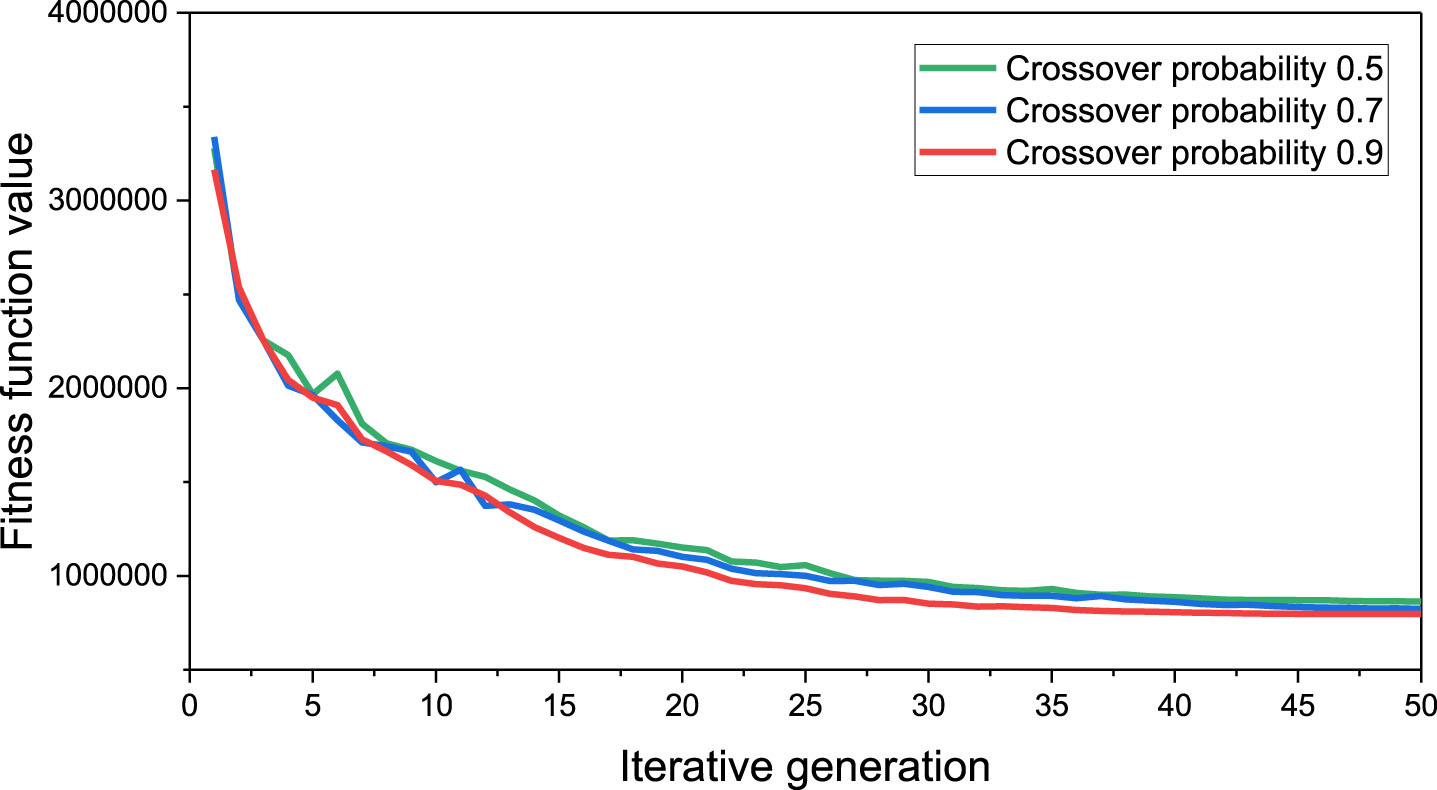
Convergent curve of different crossover probability.

Convergent curve of different mutation factor.
In order to further illustrate the advantages of the proposed improved GA, the algorithm is compared with several other common algorithms for layout design problems, including tabu search algorithm (TS) and chaos particle swarm optimization algorithm (CPSO). The comparative test is carried out based on several cases of facility location problems of different sizes in OR-LIBRARY database.
The comparative test results of different algorithms are shown in Table 1. In this table, LOCAL represents the actual optimal solution for each case. For case size, m represents the number of stations and n represents the number of wells. As can be seen from Table 1, when the size of the case is small, the advantage of improved GA is not obvious. Compared with TS, improved GA takes more time, and compared with CPSO, the optimal solution is worse. However, as the case size increases, the efficiency advantage of improved GA becomes more and more prominent. Improved GA can converge to the optimal solution faster, and the solution effect is better. Considering that the optimization case below is a large-scale coalbed methane field in China, the size of the case is relatively large, and multi-stage global optimization solution is needed. Therefore, the improved genetic algorithm will be used to optimize the coalbed methane field case.
Comparison of algorithm optimization results
Comparison of algorithm optimization results
Based on the global optimization algorithm proposed in this paper, the global optimization solution program of star-tree gas pipeline network is developed through IDEA integrated development environment and Java and SpringBoot framework, so as to obtain the optimal pipeline network layout scheme. For data interaction, MYSQL database is used as the operation database for pipeline network layout design, and Mybatis is used for interactive operation between database and JAVA. In order to improve the simplicity and readability of the code, the design idea of Aspect Oriented Programming (AOP) in SpringBoot framework is adopted in the iterative calculation module design, and the gas parameters and pipeline structure parameters are updated in the design of pipeline node connection.
Case study
In order to further verify the effectiveness of the mathematical model and solution algorithm, a coalbed methane field in China was selected as an example to optimize the solution. The coalbed methane field contains 93 single wells, and the well location distribution of each single well is shown in Fig. 10. The original pipeline network structure is shown in Fig. 11. It can be seen from Fig. 11 that under the original pipeline network layout, there are 15 valve sets and 1 station, and the station is not built on the original valve set location, but a new site location is added. Figure 12 shows in detail the membership relationship between the well and the valve set in the original pipeline network structure. As can be seen from Fig. 12, the number of wells managed by each valve set ranges from 3 to 9. Among them, the number of wells administered by valve sets W37 and W63 was the least, with 3 wells each. Valve set W64 had the largest well number of 9. In the original pipeline network layout scheme, the investment cost of the valve set is 834.68×10⁴ RMB. The investment cost of the production pipeline is 4557.92×104 RMB. The investment cost of the gathering pipeline network is 258.2×10⁴ RMB, and the total investment is 5650.8×104 RMB. In addition, the production process parameters of wells are shown in Table 2, involving well production, wellhead temperature, wellhead pressure and other parameters.
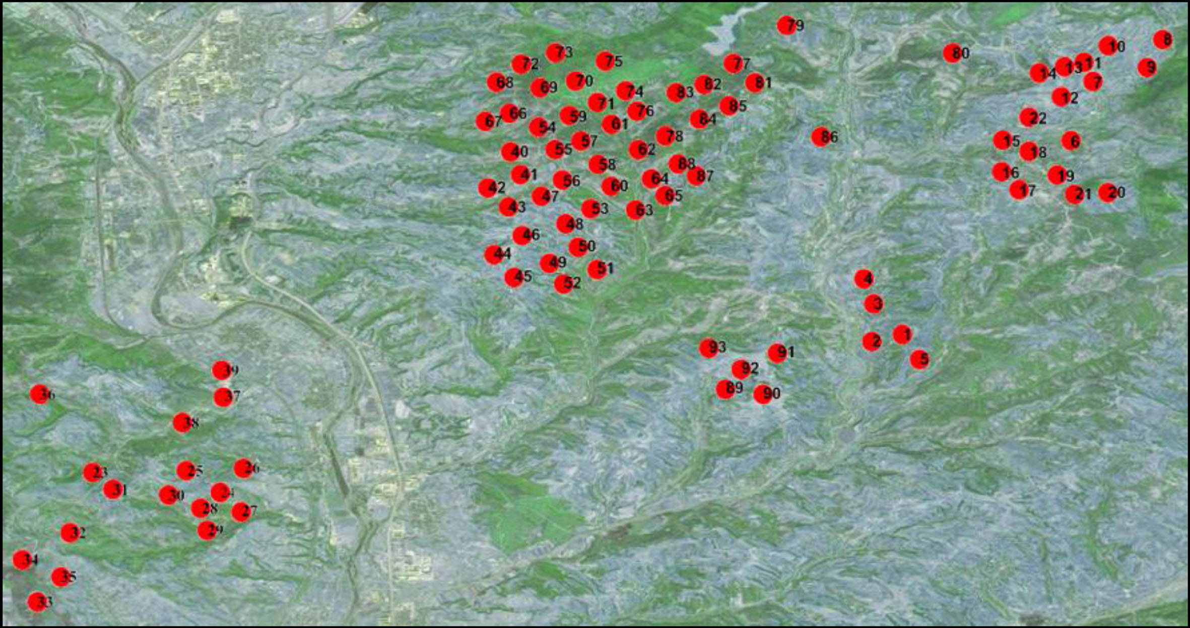
Diagram of well location coordinates.
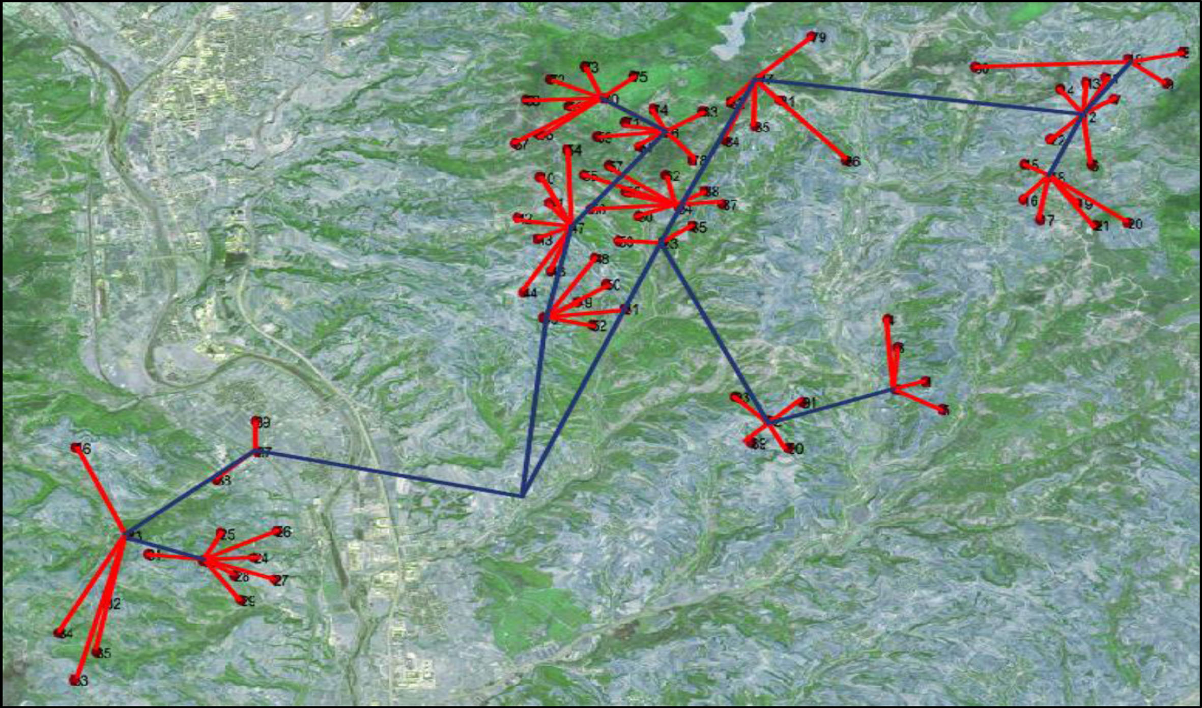
Diagram of original pipeline network structure.

The well and valve set membership in the original pipeline network structure.
Well production process parameters
In the solution of the coalbed methane field case, the population number of the improved GA is set as 150, the maximum number of iterations is 200, the crossover mode is multi-point crossover, the crossover probability is 0.9, and the mutation factor is 0.0004. The optimal pipeline network layout scheme of the coalbed methane field is successfully solved by the proposed improved GA. The iteration curve of improved GA is shown in Fig. 13. It can be seen from this figure that the convergence curve decreases at a fast rate at the beginning. After 100 iterations, the curve gradually slows down. Finally, after 175 iterations, the curve flattens out and converges to the optimal solution.
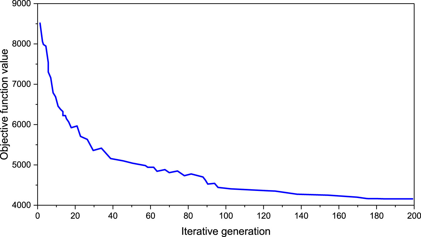
Objective function optimization process.
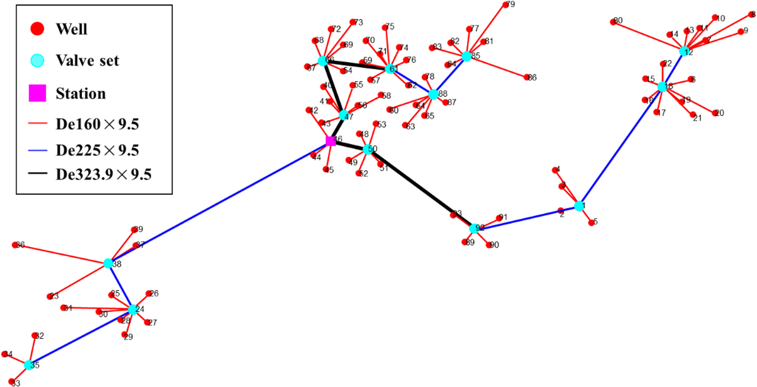
The optimized star-tree pipeline network layout scheme is shown in Fig. 14. It can be seen from Fig. 14 that there are 13 valve sets and 1 station. The production pipelines between the wells and the valve sets are 160×9.5 mm in size. The gathering pipelines between the valve sets and the station has two specifications, 225×9.5 mm and 323.9×9.5 mm respectively. In addition, Fig. 15 details the membership relationship between the wells and the valve sets in the global optimization scheme. As can be seen from Fig. 15, the well number governed by the valve sets range from 4 to 9. Valve set W35 has the least well number of 4. The valve sets W13 and W18 have the largest well number of 9.

Global optimization result of star-tree pipeline network layout.
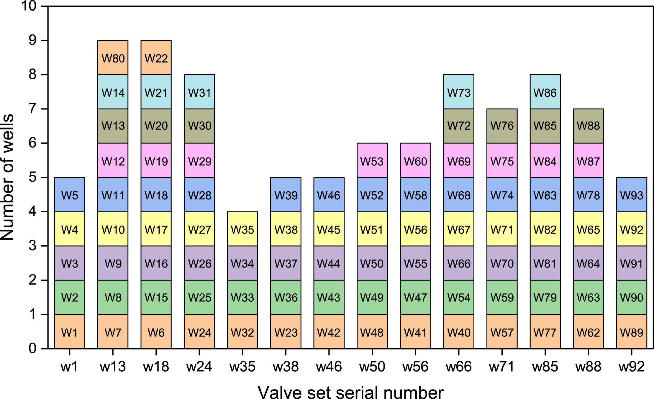
Well and valve set membership in the global optimization schem.
The investment cost comparison between the global optimization scheme and the original scheme is shown in Table 3. It can be seen from Table 3 that the total investment cost of the global optimization scheme is 4161.06×104 RMB, which is 1489.74×104 RMB less than the original scheme, accounting for about 26.36%. It can be seen that the global optimization scheme has achieved a substantial reduction in investment cost, which can bring huge economic benefits to investors. By comparing the sub-investment costs, it is found that the investment cost of the production pipeline under the global optimization scheme is 3266.73×104 RMB, which is 1291.19×104 RMB less than the original scheme. This is the main reason why the global optimization scheme is more cost-effective than the original scheme in terms of total investment. In addition, the global optimization scheme also has a certain degree of economic advantages in terms of valve set investment and gathering pipeline investment.
Investment cost comparison
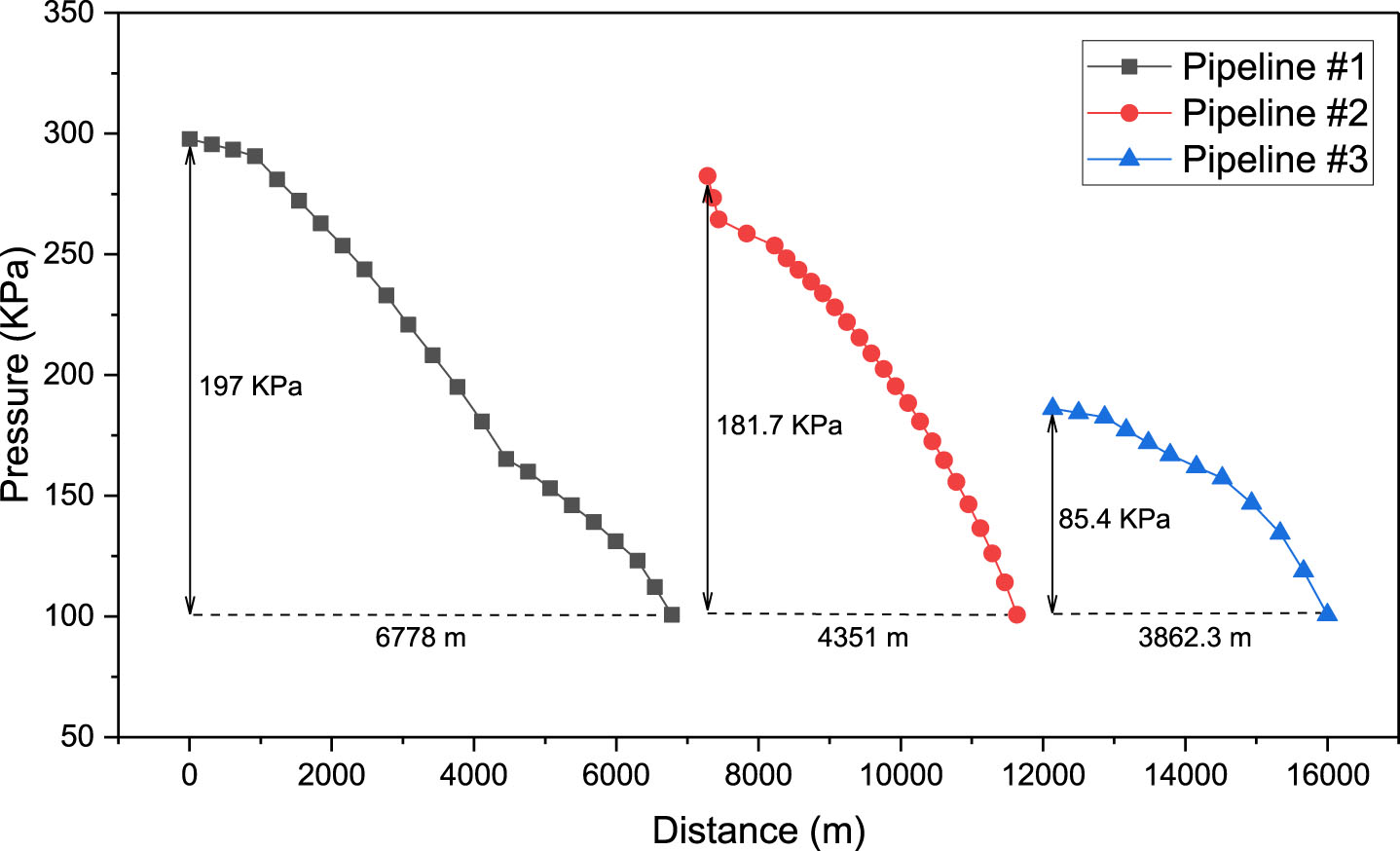
In order to verify the feasibility of the global optimization scheme, a calculation model of pipeline network hydraulic pressure drop was established by using PIPESIM software. Based on this model, combined with the gas production flow and pressure of each single well under the design conditions, the hydraulic pressure drop results of the pipeline network are calculated, as shown in Fig. 16. It can be seen from Fig. 16 that the hydraulic pressure drop of each pipeline is within the required range of 300 KPa. Pipeline #1 has the highest hydraulic pressure drop at 197 KPa. Pipeline #2 is 181.7 KPa. The hydraulic pressure drop of Pipeline #3 is the lowest at 85.4 KPa. Therefore, in the actual operation process, more attention should be paid to the process parameters of Pipeline #1 and Pipeline #2 to ensure the safe and stable operation of the pipeline network system.
Pipeline network hydraulic pressure drop results.
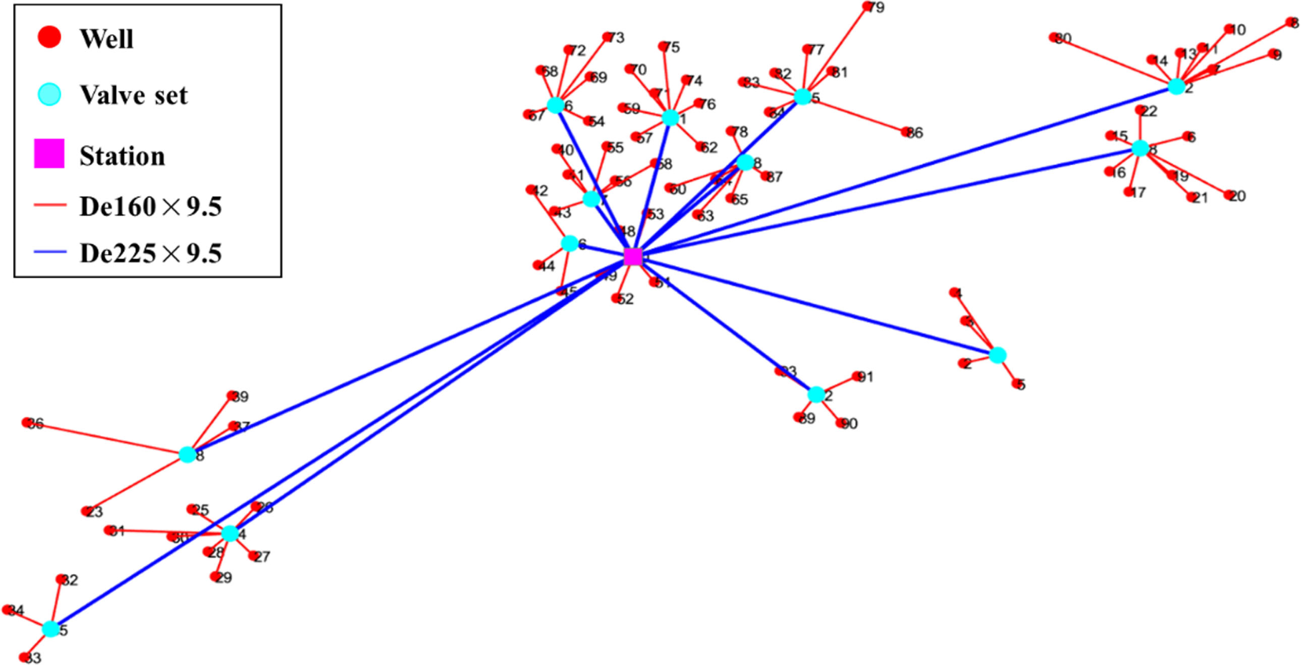
In order to further verify the superiority of the star-tree pipeline network layout scheme obtained by the global optimization method. The two-stage hierarchical optimization method is used to solve the star-tree layout scheme and the star-star layout scheme of the coalbed methane field. The two-stage hierarchical optimization method divides the entire optimization problem into two sub-problems. The first stage is the layout optimization of the star topology production pipeline network between single wells and valve sets, including well group division, valve set position determination, and the connection relationship between well and valve set determination. After the optimal layout scheme of star topology production pipeline network is determined, the layout optimization solution of the tree topology or star topology gathering pipeline network between the valve sets and the station in the second stage is carried out, which involves the determination of the number and the location of station, and the determination of the connection relationship of the pipeline network. Finally, the optimal star-tree pipeline network layout scheme of the gas field obtained by the two-stage hierarchical optimization method is shown in Fig. 17, and the optimal star-star pipeline network layout scheme is shown in Fig. 18.
Star-tree pipeline network hierarchical optimization layout result.
Star-star pipeline network hierarchical optimization layout result.
In order to further verify the superiority of the star-tree pipeline network layout scheme obtained by the global optimization method. The two-stage hierarchical optimization method is used to solve the star-tree layout scheme and the star-star layout scheme of the coalbed methane field. The two-stage hierarchical optimization method divides the entire optimization problem into two sub-problems. The first stage is the layout optimization of the star topology production pipeline network between single wells and valve sets, including well group division, valve set position determination, and the connection relationship between well and valve set determination. After the optimal layout scheme of star topology production pipeline network is determined, the layout optimization solution of the tree topology or star topology gathering pipeline network between the valve sets and the station in the second stage is carried out, which involves the determination of the number and the location of station, and the determination of the connection relationship of the pipeline network. Finally, the optimal star-tree pipeline network layout scheme of the gas field obtained by the two-stage hierarchical optimization method is shown in Fig. 17, and the optimal star-star pipeline network layout scheme is shown in Fig. 18.
Figure 19 shows the comparison of the investment cost of the star-tree global optimization scheme, the star-tree hierarchical optimization scheme and the star-star hierarchical optimization scheme. On the whole, the total investment of the star-star hierarchical optimization scheme is 4938.28×104 RMB, while the total investment of the star-tree hierarchical optimization scheme and the star-tree global optimization scheme is 4728.28×104 RMB and 4161.06×104 RMB respectively. Therefore, the investment cost of the two star-tree schemes is better than that of the star-star scheme. This is because in this gas field, some valve sets are located in remote locations. If the valve sets are directly connected with the station in a one-to-one way (star topology), the construction investment cost of the gathering pipeline will be greatly increased, resulting in an increase in the total investment cost.
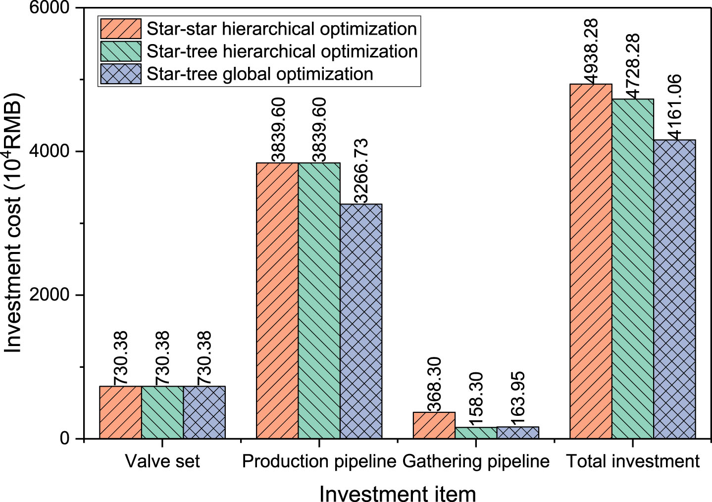
Investment cost comparison.
By comparing the star-tree global optimization scheme with the star-tree hierarchical optimization scheme, it is found that the global optimization scheme saves the total investment cost of 567.22×10⁴ RMB compared with the hierarchical optimization scheme, and the investment cost is reduced by 12% (Fig. 19). Comparing the sub-investment costs, it is found that the global optimization scheme is consistent with the valve set investment of the hierarchical optimization scheme. This is because the number of valve sets designed by the two schemes is the same, both of which are 14 valve sets. However, combining the two pipeline network layout diagrams, it can be seen that when the number of valve sets is the same, the valve set positions of the two schemes are different. The change of the position of the valve set further resulted in the change of the connection relationship between the well, valve set, and station. Combining with Fig. 19, it can be seen that this change reduces the cost of production pipelines in the global optimization scheme by 572.87×10⁴ RMB compared with the hierarchical optimization scheme, while the cost of gathering pipelines increases by 5.65×10⁴ RMB. But in general, the investment cost of the global optimization scheme is significantly lower than that of the hierarchical optimization scheme. This further proves the adaptability and superiority of the global optimization method in solving the optimization problem of star-tree pipeline network layout.
In this paper, an optimization model of star-tree gas gathering pipeline network layout in discrete space is established. On the basis of gas flow balance constraint, facility connection relation constraint and gathering radius constraint, the model also considers the hydraulic characteristics of pipeline, so as to ensure the feasibility of gas transmission and the rationality of pipeline structure parameter selection. In order to ensure the optimality of solution, this paper proposes a global optimization strategy and uses improved GA to solve the model. The optimization model and solution method are applied to a coalbed methane gathering pipeline system in China, and the optimal layout scheme of the pipeline network is solved successfully, which verifies the effectiveness of the global optimization solution method.
The optimization results shows that the global optimization scheme saves 1489.74×104 RMB (26.36%) in investment cost compared with the original scheme, and the optimization effect is significant. Such huge cost savings mainly come from the production pipeline. The investment of the production pipeline under the global optimization scheme saves 1291.19×104 RMB compared with the original scheme. In addition, by comparing the global optimization scheme with the hierarchical optimization scheme, it is found that although the hierarchical optimization scheme reduces the investment cost of 922.52×10⁴ RMB, there is still a big gap compared with the global optimization scheme. It is further proved that the global optimization method can bring huge economic benefits for gas field construction.
Nomenclature
Data availability statement
All data, models, and code generated or used during the study appear in the published article.
Footnotes
Acknowledgments
The authors would like to express sincere acknowledgements to the National Natural Science Foundation of China (51704253) for the financial support in this project.