
Abstract
In the modern power system, the use of renewable energy sources is increasing rapidly, which makes the system more sensitive. Therefore, it requires effective controllers to operate within the allowable ranges. The existing techniques based on cascaded controllers implemented so far for load frequency control have the advantage of improving the system response. However, this makes the system a more complex and time-consuming process. This makes the system more straightforward, makes it easy to optimize PID parameters, and provides results in acceptable ranges. This paper attempts to solve the load frequency control (LFC) problem in an interconnected hybrid power system with a classical PID controller employing the tunicate swarm algorithm (TSA). This algorithm is used for two areas of an interconnected hybrid power system: thermal, hydro, nuclear, and wind. The PID controller parameters are optimized by tunicate swarm algorithm using integral time absolute error (ITAE) based objective function. To show the robustness of the proposed TSA algorithm, a sensitivity analysis is performed for four case studies ranging from 20% to 30% load increments and decrements. The performance of the proposed TSA algorithm has been compared with the well-known optimization algorithms, particle swarm optimization (PSO), artificial bee colony (ABC), and arithmetic optimization algorithm (AOA) in terms of overshoot, undershoot, and settling time. The simulation results show that the proposed TSA has better optimization capability than PSO, ABC, and AOA in terms of overshoot, undershoot, and settling time.
Keywords
Introduction
The penetration of renewable energy sources (RES) worldwide for electricity generation is enhancing and trending upward [1, 2]. The electrical energy demand is increasing rapidly. On the other hand, fossil fuel reserves are finite, and environmental concerns about greenhouse gas emissions drive the development of new-generation technologies [3]. Power generated by renewable resources is unpredictable; depending upon the location, the output power generated is not constant and presents significant variations over time [4]. A hybrid combination of renewable energy with conventional systems causes various impacts on the control and operation of power [5, 6]. Controlling frequency variation in power systems is a crucial topic that has spurred many studies [7, 8]. The synchronous machine’s rotational speed determines the frequency. The balance in active power in the system is directly connected to frequency. The power variations caused by the interconnection of renewable energy sources may induce active power, resulting in frequency deviations from the operating norm. To deal with these scenarios, control systems have been put in place. Machine inertia causes changes in the operational speed of synchronous units, and primary and secondary control techniques (i.e., load frequency control (LFC) and AGC) restore system frequency within allowed limits. PV and wind are the most widely used renewable energy resources on the planet, and the frequency constancy requirements and methodologies for solar photovoltaic systems [7, 8] as well as wind generation [9, 10] have been investigated extensively.
Automatic generation control (AGC) is a crucial aspect of power system operation and stability. It is responsible for maintaining the balance between the generation and load of a power system, ensuring that the system remains stable and secure. One of the most common methods of AGC is the use of a proportional-integral-derivative (PID) controller. However, the traditional PID controller has certain limitations, such as difficulty in obtaining accurate model parameters and poor performance under nonlinear and uncertain conditions
According to the literature, various strategies are used in the AGC of power systems to maintain the tie-line power flow and system frequency within their acceptable range under stable and unstable conditions. Due to its constructional simplicity, reliability, good performance, and low cost, the PID controller is a preferred choice for engineers. Additionally, it does not require a highly skilled individual to operate and requires less development effort, which is a big concern in engineering practice. Recently, novel artificial intelligence-based methodologies for optimizing the PID controller settings for the AGC system have been proposed. Several traditional controller structures have been presented and compared for an AGC of a power system, including PID, as well as its various combinations [11, 12]. Furthermore, the references [13, 14] suggested the use of bacterial foraging optimization (BFO) to enhance the PID controller settings of an interconnected power system. The results have shown that it provides a better response than a well-known genetic algorithm (GA) based controller [13, 14]. Another new technique known as the Imperialist Competitive Algorithm (ICA) to optimize the parameters of PID controller and fuzzy PID controller is proposed in [15, 16] load frequency control (LFC) of two area power systems. Laghari et al. introduce a fuzzy logic controller-based governor to regulate the frequency of a Mini hydro power plant. This was deployed in Malaysia’s existing distribution network, which comprises two mini hydro generation units running in isolated mode [17].
Furthermore, the optimization of the PI controller using the neuro-fuzzy approach to control the LFC of a four-area power system is proposed in [18, 19]. Sivalingam et al. applied a whale optimization algorithm (WOA) to investigate an adaptive fuzzy logic-based PID controller for the LFC of an autonomous power system [20]. Berwal and Singh published a paper on applying the ANFIS and PID controller technique to automatic LFC in a hybrid four-area power system [21]. To handle the autonomous generation control problem involving multi-area, multi-power systems, Gheisarnejad and Khooban used the cuckoo optimization algorithm (COA) for fine parameter tuning of fuzzy-based PID controller [22]. Chen et al. presented Improved Ant Colony Optimization (IACO) based algorithm for a fuzzy PID (FPID) controller to provide the two-area power system load frequency control [23]. Saurabh et al. presented a moth Flame optimization (MFO) based fractional order PID controller and tested it on two systems (single & two area power systems) [24]. Sahin investigated a higher-order feedback controller and designed it for the LFC of an interconnected power system [25]. Tripathy et al., in their research work, optimized the fuzzy PD-PI cascaded controller parameters using the grasshopper optimization algorithm (GHO) for the LFC of a two-area interconnected hybrid power system [26]. Tiacharoen researched a PSO-based two-degree-of-freedom PID controller (2-DOF PID) for LFC in a two-area hybrid power system [27]. Irudayaraj et al. employed the chaotic-based atom search optimization (COAs) to optimize the FOPID controller for the LFC of a two-area hybrid power system [28]. Srivastava et al. developed a grasshopper optimization algorithm (GOA) based on PID and a two-stage (PI)-(1 + PD) controller for the LFC of two areas hybrid power system [29]. Abou El-Ela et al. propose a COAs-based PID controller design for the LFC of two area hybrid power systems [30]. An improved objective function of Integral time absolute error (ITAE) is employed for optimizing PI controller parameters using the Differential Evolution algorithm. Due to this, the results have shown superior performance compared to bacterial foraging optimization algorithm (BFOA) and GA-based optimized PI controllers [31].
Furthermore, the literature also shows that improving a power system’s efficiency depends on artificial technology and objective function. As a result, developing and deploying new high-performance heuristic optimization techniques is always valued. Recently, there has been a growing interest in using swarm intelligence-based algorithms for optimization and control in power systems. One such algorithm is the Tunicate Swarm Algorithm (TSA). TSA is a bio-inspired optimization algorithm that is based on the behavior of tunicate colonies, which are marine invertebrates that have the ability to form colonies and adapt to changing environmental conditions. Satnam Kaur et al. proposed a Tunicate swarm method, a unique biologically inspired metaheuristic algorithm for optimizing non-linear constrained problems. It was modeled on tunicate swarm behavior, which allows them to survive in the deep ocean. TSA outperforms artificial bee colony (ABC), particle swarm optimization (PSO), genetic algorithm (GA), spotted hyena optimization (SHO), and gray wolf optimization (GWO) on 74 benchmark functions and a variety of engineering issues. Applying several algorithms to engineering problems reveals that TSA outperforms ABC, PSO, GA, SHO, and GWO [32]. As a method for global optimization, TSA aims to comb through the available options and, most of the time, offer the best one.
In light of the preceding, this paper attempts to apply a TSA for the AGC of a two-area interconnected hybrid power system. PID controllers are considered for each area, and TSA is used to optimize the controller’s parameters by using integral time absolute error (ITAE) as an objective function. Performing Sensitivity analyses of the suggested technique against well-known algorithms such as PSO, ABC, and AOA for various load deviation scenarios indicates that the proposed design approach is better in terms of undershoot, overshoot, and settling time.
Mathematical modelling of various power system
Wind energy conversion system model
The model of a wind energy resource using the transfer function is shown in Fig. 1 [33]. The controller settings for the second-order dynamics of a wind energy resource are determined by selecting the appropriate frequency ω
n
and damping factor ζ as shown in equation below.
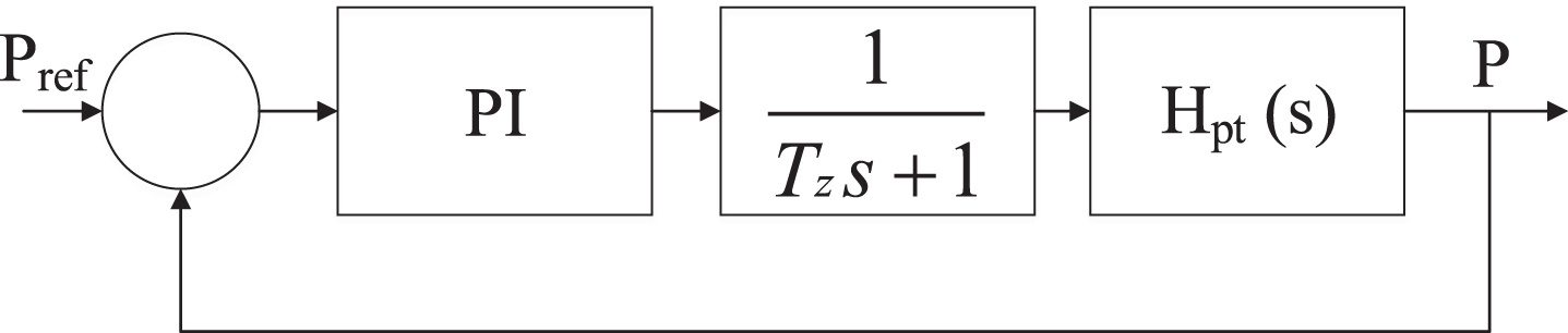
Wind energy conversion system.
A high K
p
number ensures superior tracking performance, but the control effect is limited, hence K
p
must be limited. The reference signal’s first-order filtering compensates for the rise in overshoot. The following transfer function can be used to describe its dynamic behavior:
The parasitic and main time constants are T pt and TΣ, respectively. Figure 1 depicts its closed loop transfer function employing PI control.
The wind plant model designed in Matlab Simulink is shown in Fig. 2.
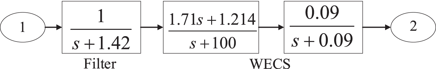
Wind plant model designed in Matlab Simulink.
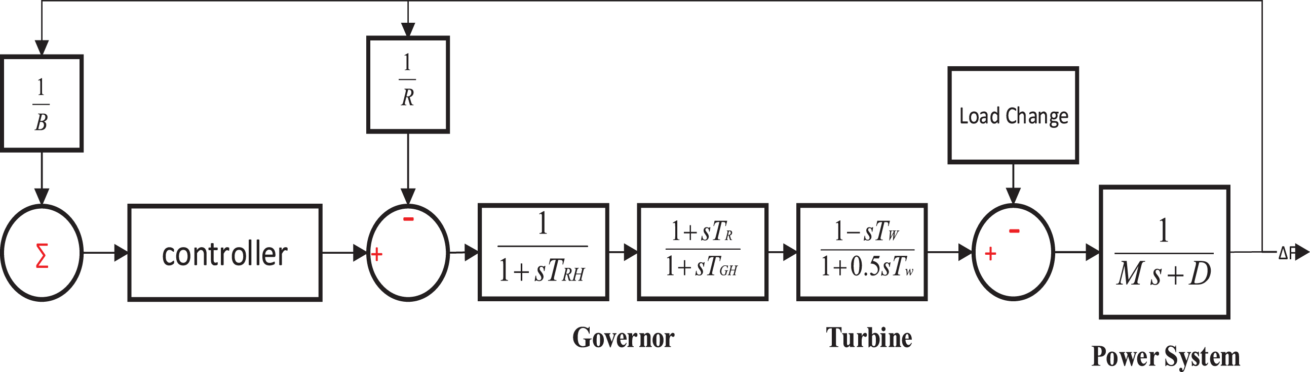
The thermal power plant model using the transfer function is shown in Fig. 3. Model contains a controller, governor, and turbine as its main components. T T and T G are the turbine and governor time constants respectively.

Transfer function-based model of Thermal power plant.
The thermal and hydropower systems model is frequently used in the literature to study the behavior of hybrid systems under stable and unstable conditions [34]. The transfer function-based thermal and hydropower systems models utilized in this study are shown in Figs. 4 and 5.

Transfer function model of Thermal Power plant.
Isolated Hydro power plant model.
Figure 5 presents the hydropower plant model using the transfer function. It utilizes a controller, mechanical-hydraulic governor, and turbine. T RH and T GH are governor time constants. T w is the turbine time constant. Hydropower plant model in Matlab Simulink considered in this research is shown in Fig. 6.

Isolated Transfer function model of Hydro Power Plant.
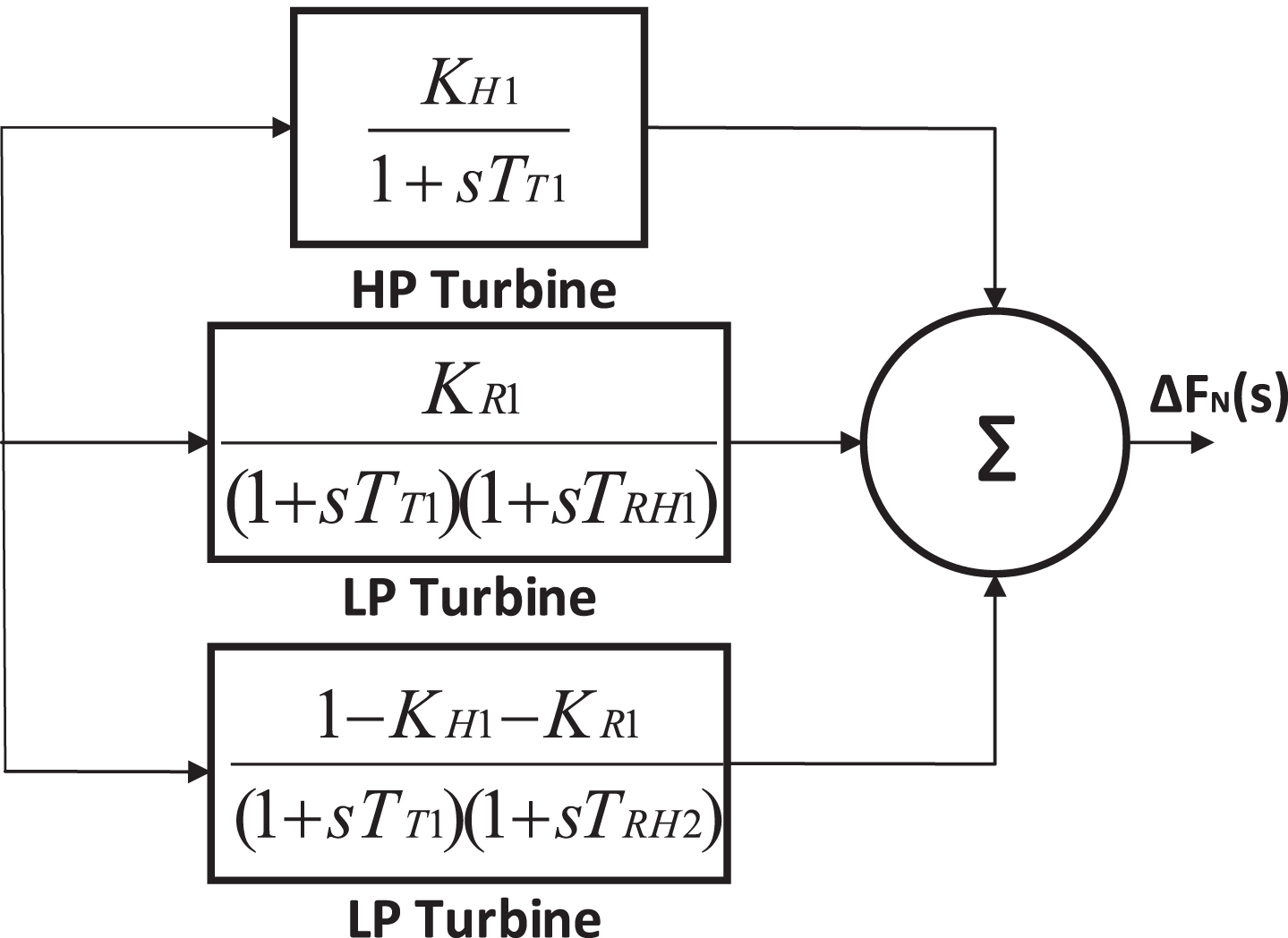
Figure 7 represents the nuclear power plant model using the transfer function.
Transfer function based model of Isolated Nuclear plant.
This nuclear power plant is considered with tandem compound turbines, two Low pressure (LP) sections with high-pressure (HP) reheater, and one HP section [35].
The isolated transfer function-based Matlab Simulink Nuclear power system model used in this research is given in Fig. 8.

Nuclear Power Plant model.
The generalized two-area hybrid power system model using the transfer function is shown in Fig. 9.

Two area hybrid power system model.
Figure 10 depicts the power plant model considered in this paper consists of two are hybrid power plants. Each area contains a hybrid network of Thermal, Hydro, Nuclear, and Wind power plant as presented in Fig. 11.

Two area Interconnected Hybrid Power System.
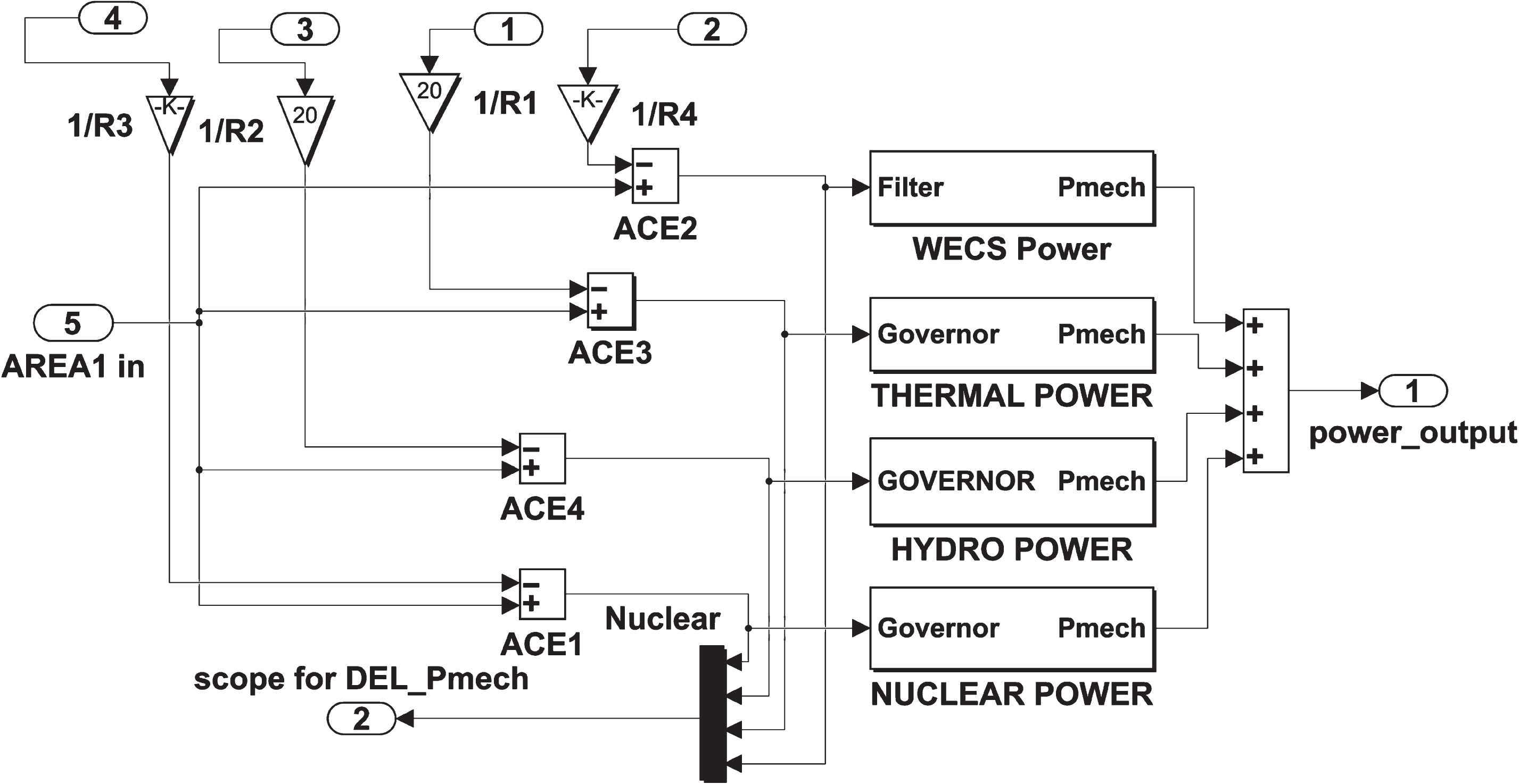
Subsystem of area1 contains four sub-subsystems.
Here only a single area is explained, whereas others have the same blocks and parameters.
B1 and B2 indicate the frequency bias parameters and ACE1 and ACE2 shows the area control errors R1 to R4 are the governor speed regulation of hydro, thermal, nuclear and wind in p.u respectively. ΔP Tie represents the incremental change in tie line power (p.u). M = 2 H where H is the inertia constant of each machine, D1 and D2 are load damping constant, T12 is the synchronization coefficient, while TP1 and TP2 are the power system time constants in seconds. ΔF1 and ΔF2 shows the frequency change in area1 and area2 respectively.
The detailed mathematical modeling of the proposed algorithm is discussed in this section.
Optimization algorithm with mathematical modeling
Tunicate has the potential to locate food supply in the deep sea. However, there needs to be more information regarding the food source in the specific search space. This article uses two tunicate behaviors (optimal solution) to find the most excellent food source. Swarm intelligence and jet propulsion are those two phenomena. The suggested mathematical model of jet propulsion must meet the three requirements. It must travel toward the position of the best search agent, stay near that search agent, and avoid clashes with other search agents. On the other hand, the swarm activity will help other particles stay informed about the best-optimized answer.
Method to Avoid dispute between the search agents
To prevent conflicts between search agents (i.e., other tunicates), vector
Conflict avoidance between search agents.
In the deep ocean, however, vector G represents gravity and vector F represents water flow advection. The variables c1 to c3 are in the range [0, 1]. social forces between search agents is denoted by vector M.
P max and P min represent the final and initial speeds for social engagement, respectively. In this research paper, the value of P min is chosen as 1 and for P max is 4 as suggested in [32].
Search particle movement follows the direction of best neighbors to prevent disputes between other search agents, as shown in Fig. 13.
Vector PD shows the space between the food supply and the search agent. The tunicate position is indicated by the vector Pp(x), and random number between [0, 1] is denoted by r and . Vector FS denotes the food source position.
Search agent’s movement towards the best neighbor.
The search agent is constantly shifting its position in relation to the ideal search agent, as shown in Fig. 14. Here food source based updated tunicates position is denoted by P
p
(x).

Converge towards best search agent position.
The first two solutions are used to modify the position and movements of search agents in order to decrease the tunicate’s swarm movement. Equation 9 here defines tunicate swarm behavior
How the position of search agents is updated in accordance with the location of vector P p (x) is depicts in Fig. 15. Tunicate position specifies an arbitrary location within a cone-shaped structure for the final position.
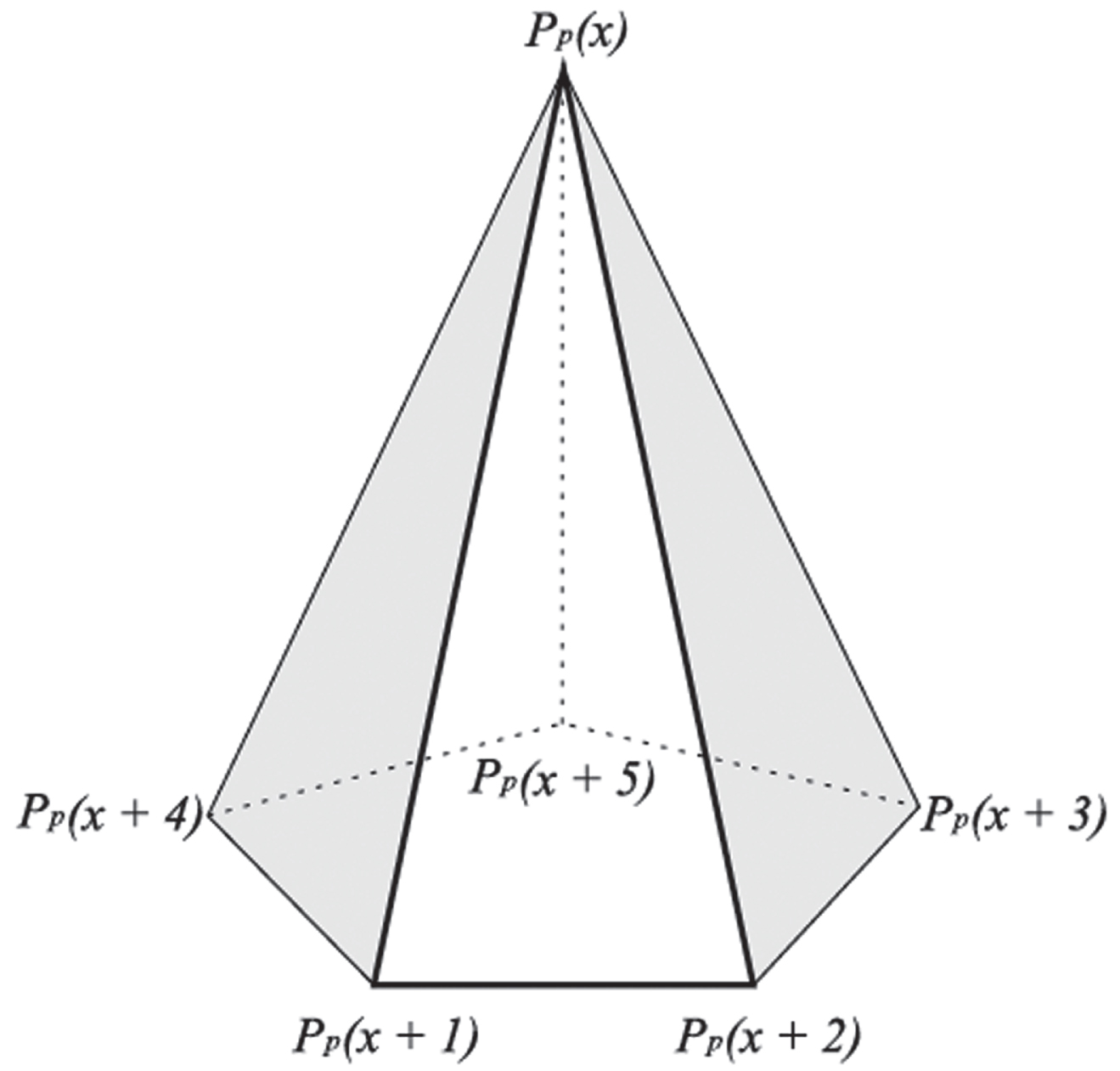
3D tunicate position.
The flowchart of the TSA are given below.

Flowchart of the TSA algorithm.
Quickly reduction in the frequency and tie-line power change to zero is the primary goal of the secondary controller after a sudden perturbation in load. A TSA-based optimized PID controller is proposed to accomplish this task. ACE triggers the controller action when any of the regulated areas is disrupted by a sudden change in load, reducing the ACE to zero. It has a mathematical definition as follows:
Here ACE1 and ACE2 denote the area control error of areas 1 and 2, respectively. The plant’s controlled inputs (U1, U2) are as follows:
Where KP, KI, and KD are gains of the PID-controller that must be optimized through the proposed TSA algorithm. When selecting PID-controller gains, it is critical to select a performance index appropriate for the issue structure to achieve good dynamic responses in all operating situations. Selection of the controller gains is one of the common problems in control system design. System performance becomes sluggish at Lower controller gains, whereas high gains result in an excessively oscillatory system response, posing a risk of instability. Between these two extremes, there is a basic controller gains choice that may result in the system’s good performance.
The LFC’s primary goal is reducing the ACE area value to zero efficiencies. The objective function selection in an optimum control system is made either by considering the complete time response or a specific period. In optimal control theory, the integral criteria are the most often used performance index. Integral time absolute error (ITAE), integral absolute error (IAE), integral square error (ISE), and integral time square error (ITSE) are some of the most often used performance indexes based on integral criteria. The optimum response for any of the aforementioned performance indices correlates to the minimum value of the selected fitness function (i.e., objective function) and superior system specifications such as overshoot, undershoot, settling time, etc.
The integral square error is a system performance indicator calculated by squaring the error value and integrating it over a specific time interval. More significant errors will be penalized by ISE than little faults. It has a shorter overshoot but a more extended settling period. The time response of the ITSE and ITAE compared to ISE and IAE is much faster due to the additional multiplication of time with the error function. ITAE gives far greater weight to errors that come after a long period of time than the start of the response, resulting in a shorter time for system oscillation settling. The ITAE also ensures that overrun is kept to a minimum. The ITSE objective-based controller, on the other hand, provides a large controller output for a quick change in reference value, which is undesirable from a controller design standpoint. The system’s performance is enhanced significantly by using an ITAE-based objective function compared to the aforementioned indices, as described in [36, 37]. Equation 12 represents formulation of the ITAE objective function,
In this context, LFC can be viewed as a constrained optimization issue, with the controller parameters acting as inequality constraints. The following is how the design problem is stated, J should be minimized. Involved in:
To determine whether the suggested algorithm is better and more efficient, it is simulated for the various load variation cases and compared with the well-known optimization algorithms PSO, ABC, and AOA with the same power system network. MATLAB/SIMULINK environment is used to develop transfer-function based model. ITAE-based fitness function is optimized (reduced) using the TSA program to evaluate optimum gains of PID controller parameters. Simulations were carried out on a dell system having a core i-5 processor of 3.30 GHz and 30 Gb RAM in the MATLAB R2021a environment.
The test system’s performance is investigated by applying various load variation cases in the area1. Initially, PID1 controllers with unknown variables (Z1-Z3) are considered as its parameters for area 1, and PID2 with unknown variables (Z4-Z6) for area 2 is considered. The TSA program initially simulates the model based on randomly generated values between the given lower and upper limits (– 3 to 3). The objective function (ITAE) is computed in Simulink and transferred to the main TSA program via workspace. Parameters that produce the minimum value of the objective function (ITAE) are used to generate a new random value for the unknown variables, and the best-optimized parameter’s value is saved from the current iteration. The search agents moved based on these best-optimized values to achieve better fitness and update the unknown parameters. These steps are repeated until the stopping condition is matched. Table 1 displays the final PID controller parameters as optimized by the various algorithms.
PID controller parameters optimized for various techniques
PID controller parameters optimized for various techniques
The findings are compared with the well-known PSO, ABC, and AOA algorithms for the same power system model based on the overshoot, undershoot, and settling time of frequency and tie-line power to assess the resilience of the optimized PID controller.
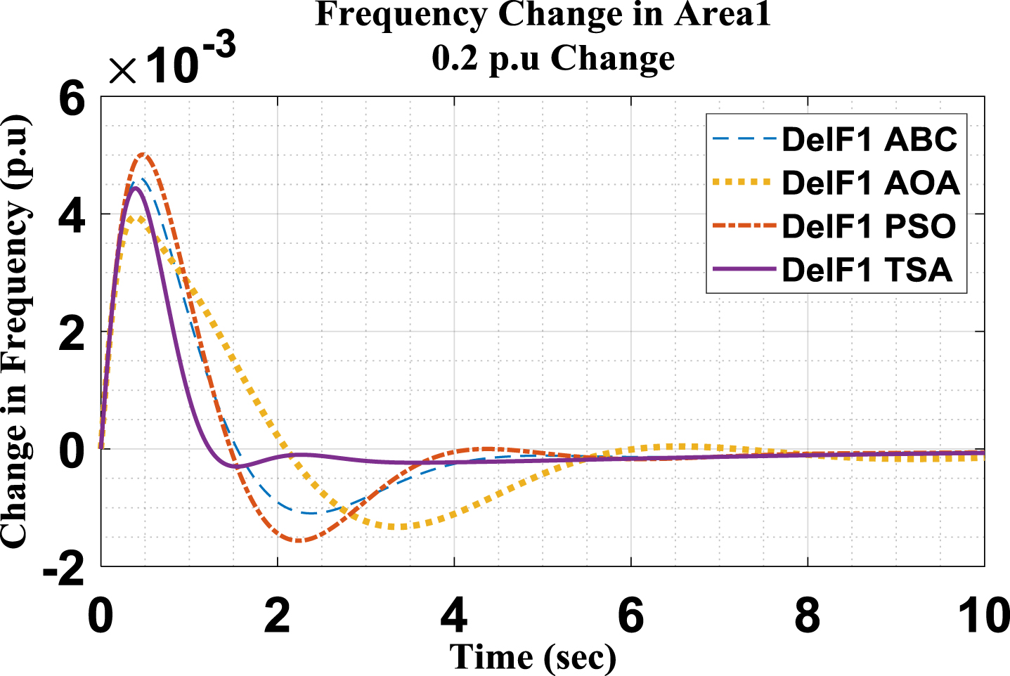
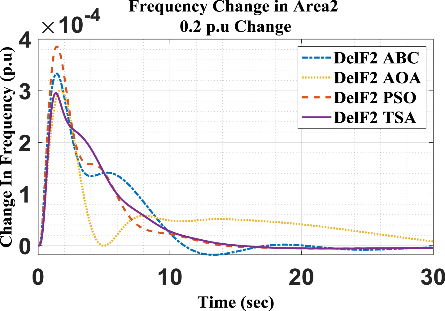
This case is simulated to observe the performance of the proposed TSA algorithm for a load increment of 20% in Area-1. However, Area-2 is operating at its normal operating conditions. The change in frequency response and tie-line power for both areas for this case is shown in Figs. 17–19.
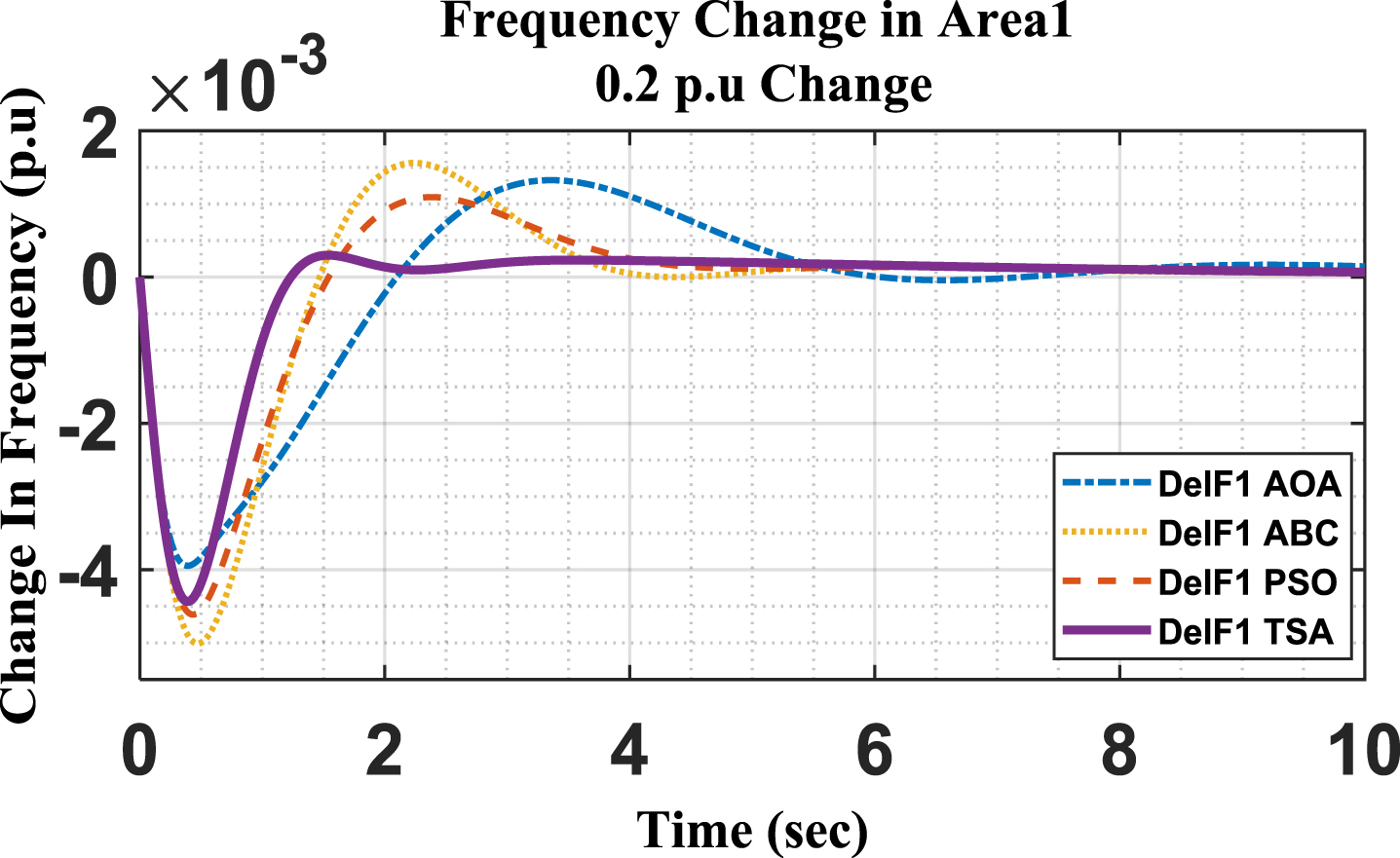
Frequency change in Area1 at 0.2 p.u change.
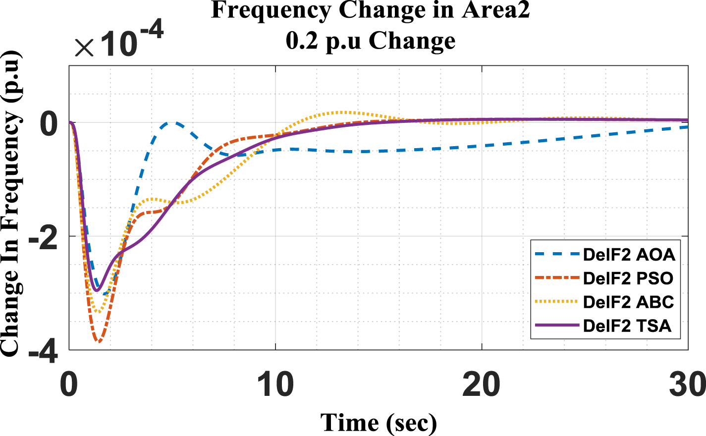
Frequency Change in Area2 at 0.2 p.u disturbance.
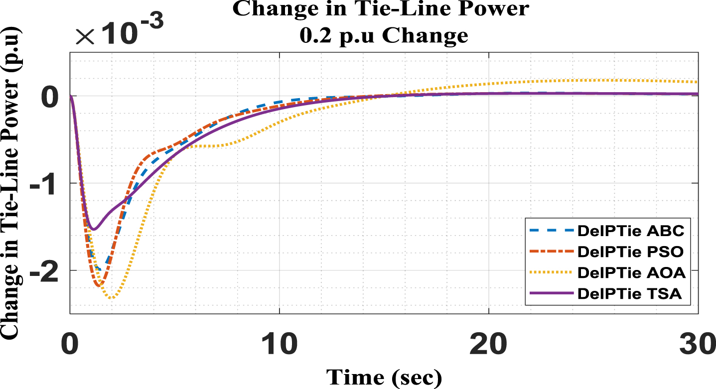
Change in Tie-Line power with 0.2 p.u change.
Furthermore, the response of all other techniques are compared in the form of Table 2, as shown below
Sensitive analysis with change of 0.2 p.u in area1
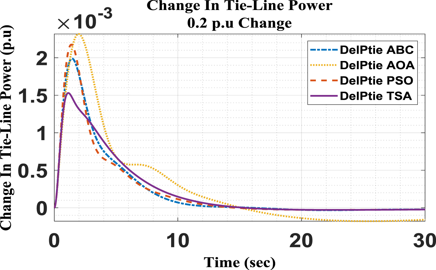
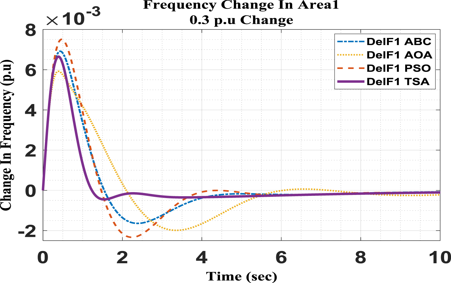
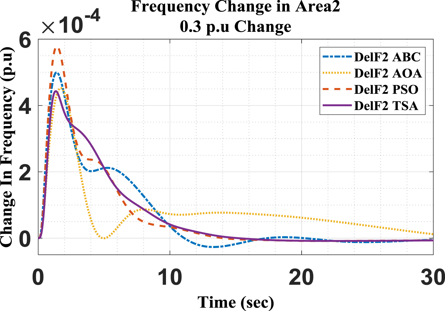
This case is simulated to observe the performance of the proposed TSA algorithm for a load increment of 30% in Area-1. However, Area-2 is operating at its normal operating conditions. The change in frequency response and tie-line power for both areas for this case is shown in Fig. 20–22.
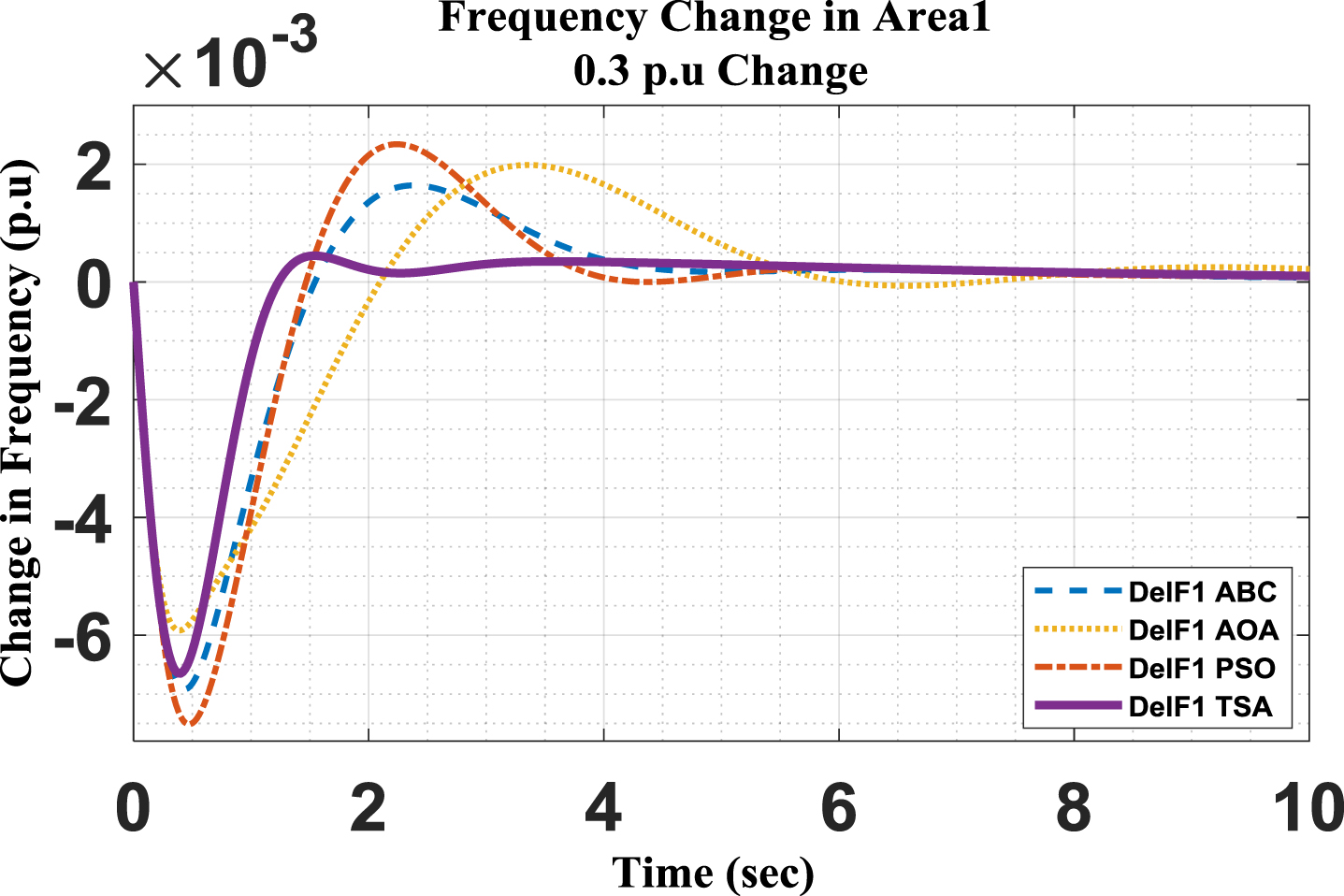
Frequency change in Area1 with 0.3 p.u change.
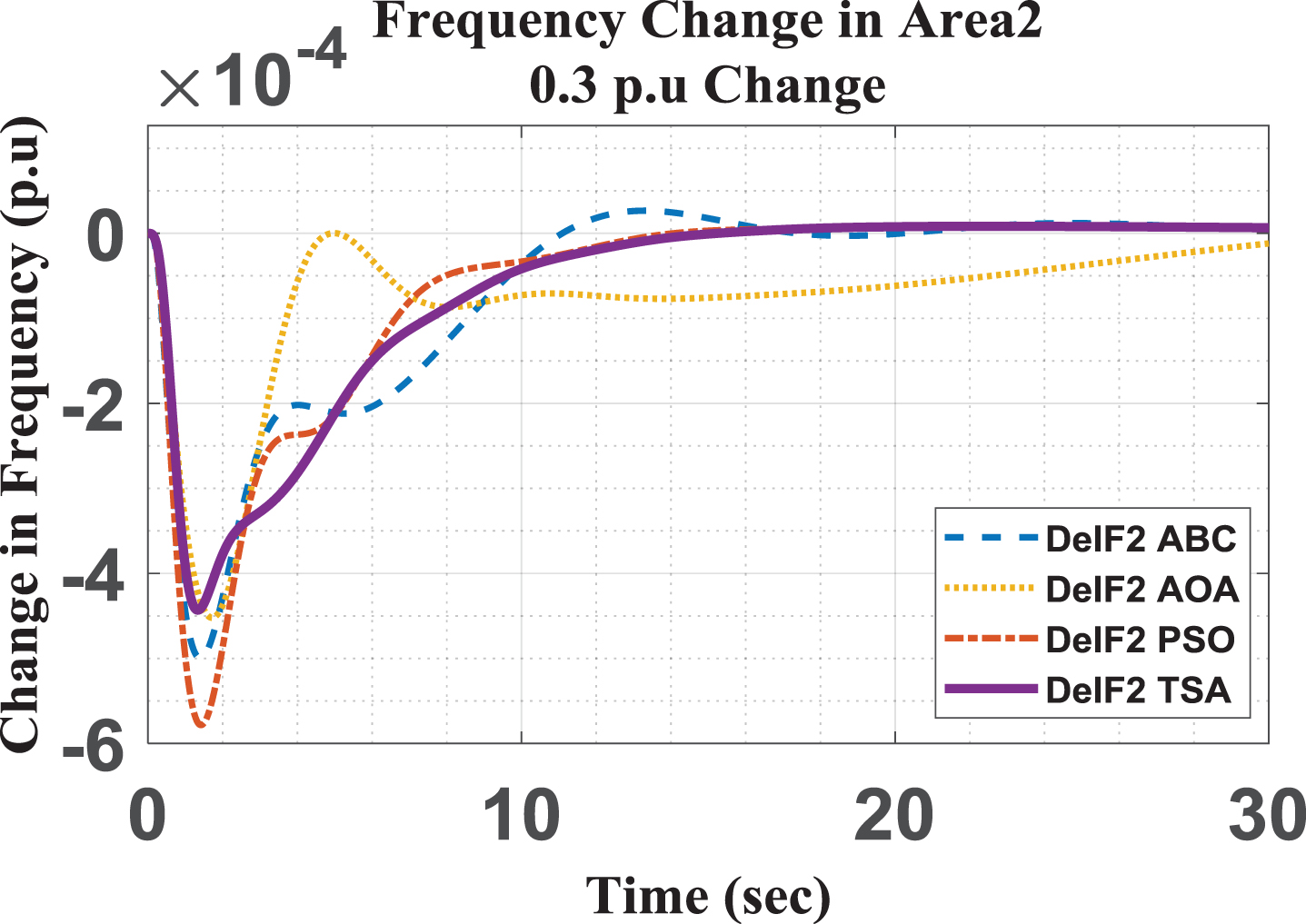
Frequency change in Area2 with 0.3 p.u change.
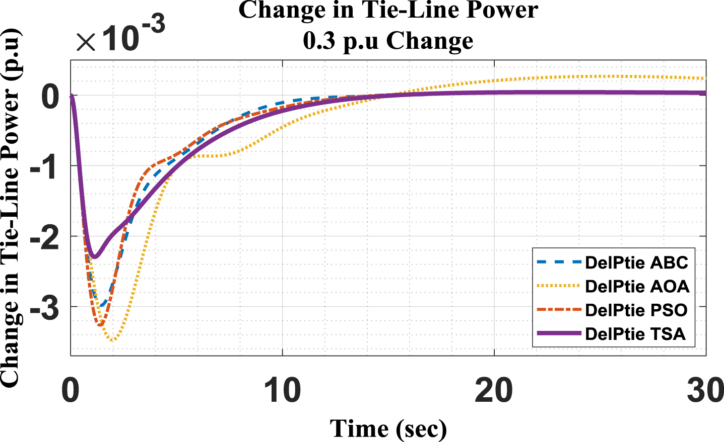
Change in Tie-Line power with 0.3 p.u change.
Furthermore, the response of all other techniques are compared in the form of Table 3 as shown below:
Sensitive analysis with change of 0.3 p.u in area1
This case is simulated to observe the performance of the proposed TSA algorithm for a load decrement of 20% in Area-1. However, Area-2 is operating at its normal operating conditions. The change in frequency response and tie-line power for both areas for this case is shown in Fig. 23–25.
Frequency change in Area1 with 0.2 p.u change.
Frequency change in Area2 with 0.2 p.u change.
Change in Tie-Line power with 0.2 p.u change.
Furthermore, the response of all other techniques are compared in the form of Table 4 as shown below:
Sensitive analysis with change of 0.2 p.u in Area-1
This case is simulated to observe the performance of the proposed TSA algorithm for a load decrement of 30% in Area-1. However, Area-2 is operating at its normal operating conditions. The change in frequency response and tie-line power for both areas for this case is shown in Fig. 26–28.
Frequency change in Area1 with 0.3 p.u change.
Frequency change in Area2 with 0.3 p.u change.

Frequency change in Area1 with 0.3 p.u change.
Sensitive analysis with change of 0.3 p.u in Area-1
Furthermore, the response of all other techniques are compared in the form of Table 5 is given above.
The results of simulations of a two-area hybrid model using various optimization strategies can be compared in terms of overshoot, undershoot, and settling time. In area-1, the proposed TSA-based controller produced 80.7%, 72.6%, and 77.5% less frequency overshoot than PSO, ABC, and AOA, respectively. In terms of undershoot, it produced 11.45% and 3.8% less frequency undershoots than PSO and ABC, respectively. Whereas TSA produced 12.4% more undershoot than AOA, TSA produced less overshoot than AOA and achieved zero steady-state error within a short interval of time than AOA.
In area-2, TSA based PID controller produced 1.998%, 68.7%, and 65.2% less frequency overshoot than PSO, ABC, and AOA, respectively. In terms of undershoot TSA based controllers produce 23.4%, 11.3%, and 2% less frequency undershoots than PSO, ABC, and AOA.
In terms of frequency settling time in area-1, TSA takes 48.6% less time than PSO and ABC and 65.6% less time than AOA. Whereas in area-2, TSA takes 33%, 24.7%, and 26.3% less time than PSO, ABC, and AOA, respectively.
Nominal values of system parameters
Nominal values of system parameters
This paper has presented the two-area hybrid power system for load frequency control. Tunicate Swarm Optimization Algorithm is considered to optimize the parameters of the PID controller. The results obtained from the simulation are compared with the well-known optimization algorithms PSO, AOA, and ABC based on undershoot, overshoot, and settling time for the various load variation conditions. From the comparison of the results, we found that TSA-based optimized PID controllers provide smooth and better responses than PSO, ABC, and AOA, as discussed in sections 4 and 5. Hence proposed algorithm-based PID controller is robust, reliable, and efficient compared with other optimization-based controllers for this system.