
Abstract
In order to improve the coordinated control effect of hierarchical power balance of new energy microgrid, this paper applies fuzzy control method to this system, and proposes a hierarchical control strategy based on event-triggered communication. Each DG is regarded as a proxy, and the continuous actual value of output is replaced by the state prediction value. Moreover, two different event trigger condition functions for frequency and voltage are designed based on Lyapunov method respectively. At the same time, each DG only communicates with its neighbor DG aperiodic at the event trigger time, and finally all DG are restored to the reference value provided by the virtual leader. Finally, this paper constructs a coordinated fuzzy control simulation system for hierarchical power balance of new energy microgrid. Combined with the simulation results, the method proposed in this paper is feasible.
Introduction
The combination of electric vehicle charging station and microgrid is not only an opportunity, but also a challenge. From the perspective of microgrid, the introduction of electric vehicles can save the purchase cost of energy storage components and the upgrading cost of system capacity for microgrid. Microgrid system with electric vehicle charging station includes two stakeholders: electric vehicle charging station and microgrid operator.
The interest of electric vehicle users is to pay the lowest charging fee to the charging station; The interests of microgrid operators are to maximize the system’s power generation capacity, reduce wind and light waste, and obtain certain economic benefits while ensuring the reliable operation of the system. The two have a certain subordinate relationship [1]. Establishing a reasonable energy management system can achieve information and energy exchange between electric vehicles and microgrids, while maximizing the economic benefits of electric vehicle users and microgrid operators. Based on the hierarchical scheduling theory, establish a hierarchical optimization energy management system for microgrids containing electric vehicle charging stations. The system consists of three parts: an independent microgrid, an electric vehicle charging station, and an optimized dispatch center. As an upper level decision-maker, microgrids formulate charging electricity prices based on their own operating conditions and transmit electricity price information to the lower level. Electric vehicle charging stations, as lower level subordinates, guide electric vehicle charging based on electricity prices [2]. Considering the reliable operation of the microgrid, the electric vehicle charging station will determine whether to discharge to the microgrid based on the supply of important loads in the microgrid. Finally, the above information is fed back to the microgrid through the optimization dispatch center. The optimization dispatch center is mainly responsible for tasks such as data collection and analysis, formulation of electricity prices, and dispatch plans. It ensures the stable and reliable operation of the microgrid and avoids the impact of electric vehicle loads [3].
The microgrid needs to be equipped with an energy management system to achieve self coordinated control, self-protection, and optimized management of the system. The output power of the microgrid is influenced by the climate conditions, geographical location, and natural environment of the installation site, and has great intermittency and volatility. For example, when the photovoltaic system is suddenly blocked by large clouds on a sunny day, its output will undergo a sudden change, If there is no energy storage unit to compensate for the power shortage, it will lead to insufficient energy supply for some loads, thereby affecting the stable operation of the entire system [4]. And most micro power sources are connected to the large power grid through inverters composed of power electronic devices, so they do not have the inertia of traditional generators, which is not conducive to the stability of system voltage and frequency. In addition, the operating mode of the microgrid changes, i.e. the parallel/off grid mode switching of the microgrid [5], and the microgrid structure changes due to the input or exit of micro power sources and loads. All of these require the microgrid energy management system to accurately and quickly monitor the operating status of the microgrid, and obtain real-time load demand, wind speed and lighting climate data, as well as the output of micro power sources and real-time electricity prices through prediction units, Based on this, coordinate and control the distributed micro power sources, energy storage, and load devices within the microgrid, develop reasonable energy management strategies, and achieve dynamic stability of voltage and frequency within the microgrid [6]. The microgrid energy management system first needs to monitor and predict the load curve within the microgrid system, weather data at the microgrid installation location, renewable energy generation system output, and then develop the optimal energy management strategy based on the predicted data and real-time operation status of the microgrid, combined with the current real-time electricity price information of the large grid, to achieve energy supply and demand balance within the microgrid, minimize the operating and environmental costs of the microgrid Different microgrid control objectives such as the highest interaction benefits with the large power grid [7].
There are two operating states of microgrids: grid connected operation and island operation. The control objectives to be achieved under different operating states are different, so they also have different control structures. For example, the voltage and frequency within the system are clamped by the large grid, and each distributed micropower source does not need to participate in the voltage and frequency regulation of the system. In order to maximize the utilization of renewable energy, the microgrid generally adopts constant power control to ensure the maximum power output of the micropower source, ensuring the power quality of the load and the grid connection power requirements. At this time, it is required that there should be a main and micro power supply in the system that can provide voltage and frequency reference. Its function is similar to that of the large power grid under grid connection conditions, and the remaining micro power sources should continue to be controlled at constant power, The system requires that the output of each microgrid be coordinated, and the power difference can be quickly compensated to achieve stable operation [8].
The master-slave control structure can be divided into two situations. One is that a distributed power source (usually an energy storage device) within the microgrid serves as the master controller, while other distributed power sources serve as slave controllers, and each micropower source adopts different control methods. In grid connected mode, all controllers adopt PQ control mode, outputting fixed active and reactive power according to scheduling instructions, and the system voltage and frequency follow the large power grid. When the system detects the occurrence of an island or the microgrid actively switches to an island state, while the other distributed units will still use PQ control. When the operating mode of the microgrid switches, there is a risk of the main controller control strategy switching failure in this control structure. In island mode, as the voltage and frequency of the microgrid system are supported by the main controller, when it is required to increase the output power, the constant voltage can only be achieved by increasing the output current, In addition, when there are significant intermittent fluctuations in the output of the remaining renewable energy or instantaneous fluctuations in the load, the main power supply should play the main regulating role, thus requiring a high level of available capacity for the main controller; In addition, in the islanded operation mode, the performance of the main controller directly affects the operation of the entire system. Once the main controller crashes, the entire microgrid system will collapse, and the reliability of the system is not high. Another master-slave control structure, where the main controller is not served by the power generation unit in the microgrid, but becomes a separate central controller. The central controller fully considers the fluctuation of load and the capacity of energy storage devices in the microgrid based on the current operating status of the system, the adjustable capacity of each micropower source, and the constraints of natural resources. It controls the output and load operation of each distributed micropower source in the microgrid in real-time, directly participating in the transient control of the microgrid, and achieving the goal of stable system operation. This control method has been widely used due to its advantages of simple structure, easy maintenance, and low cost. Its drawbacks are equally significant: as the geographical coverage of microgrids increases and distributed power sources increase, higher requirements are placed on the computing power, communication speed, and reliability of the central controller. If it fails, it may lead to the entire system being paralyzed; Moreover, as microgrid information is controlled by the central controller, once the microgrid structure changes, new distributed power sources are connected or the original distributed power sources fail, it may result in the central controller not being flexible and not easy to expand the application of microgrids [9].
The peer-to-peer control of microgrids refers to the operation control of microgrids based on their own information when there is no communication connection or less communication between micropower sources within the microgrid. Under this structure, micro power sources can achieve “plug and play", meaning that all micro power sources have the same status in the microgrid control, and their access and exit will not change the control strategy of the micro power sources in the system. Due to the same status of each inverter, each inverter adopts the same control strategy and is not limited by the operating status of the microgrid. This control strategy is called droop control (Dropcontr01). When the load inside the microgrid changes, the micropower automatically adjusts its output based on its own droop coefficient, ultimately stabilizing the microgrid at a new working point. It can also adjust its own droop characteristic curve appropriately according to the control instructions of the microgrid, Adaptive real-time balancing of system power. When the microgrid adopts peer-to-peer control, each micropower source and other micropower sources are independent of each other and can achieve their own control goals. There is no need to add additional communication devices between each micropower source, and adding micropower sources or removing faulty microgrid inverters is very convenient. The system reliability is better than that of microgrids using a master-slave control structure [10]. However, traditional droop control can only simulate primary frequency regulation in traditional power systems. When the load changes, the frequency and voltage of the microgrid using traditional droop control are usually lower than the rated voltage and frequency, and the adjustment process is differential adjustment. In order to achieve zero differential adjustment, traditional droop control must always be improved. In order to maintain the stable operation of the microgrid and achieve coordinated control of various micropower sources, it is necessary to form an effective communication topology between the inverters of each micropower source, and it may take longer to reach an agreement and determine the operation plan [11].
Under centralized control, the central controller can grasp the global information of the microgrid system. Therefore, in the centralized control framework, coordinated control of equipment within the network can be achieved through complex control and optimization methods. However, this places high demands on the computing power of the central controller and the transmission capacity of the device communication line. When the scale of the microgrid is relatively large or the control is relatively complex, the real-time and reliability of the control will be challenged; Autonomous control methods are relatively flexible compared to centralized control, with various control methods based on vertical control that mimic the characteristics of synchronous generators emerging one after another. They perform well in large-scale equipment parallel connections and have low communication requirements. However, pure autonomous control cannot optimize operation, and system stability is sensitive to changes in control parameters of the power generation unit. The hybrid control method not only neutralizes the advantages of the two mentioned above, but also to some extent compensates for their shortcomings. It can design control schemes for specific problems and is more flexible
In this paper, the hierarchical power balance of new energy microgrid is analyzed by fuzzy control method, and the corresponding model is constructed, and the corresponding model is verified and analyzed to improve the hierarchical power balance effect of new energy microgrid.
This article mainly proposes distributed controller design and event triggered controller design to address the potential issues of excessive communication data volume and channel congestion in traditional centralized controllers; In response to the issue of other researchers designing controllers for power generation and energy storage facilities separately, which increases the difficulty of deploying microgrid nodes, this paper proposes a unified controller that can integrate power generation and energy storage under unified control, which is more in line with practical engineering scenarios and easier to deploy microgrids.
Research on secondary control method of new energy microgrid
Secondary control and multi-agent theory are used to solve the power allocation error caused by insufficient line impedance and external information in droop control. Event triggering mechanisms have been proposed to address the issue of network congestion caused by high data flow in communication networks. However, in practical engineering, microgrid systems often become more complex. This chapter will further improve the model of microgrids and propose corresponding control methods based on multi-agent theory and event triggering theory
The previous research content of researchers only focused on DG or ESS separately, designing different control systems, lacking a unified control scheme that can bridge DG and ESS simultaneously. This leads to the content to be introduced in this chapter, which is the DG+ESS integrated microgrid control system. The ESS and DG in this chapter have the same droop control and secondary control functions, but ESS has an additional control objective, namely SOC equalization. At the same time, the microgrid model established in this chapter is closer to the underlying physical layer compared to the previous chapter, making it easier to apply in practical microgrid engineering. In addition, this chapter has made certain improvements in the event triggering mechanism, further reducing the number of event triggers and reducing the pressure on communication networks.
Secondary control of integrated microgrid for power generation and energy storage
In general, we think that microgrid has N buses (i = 1, 2 … N). The electrical physical network of the MG can be depicted in diagrams G MG = (V MG , E MG ) where nodes V MG represent buses and edges E MG ⊆ V MG × V MG represent line connections. If there is line connection between the i-th node and the j-th node, then Zij = Rij + jXij, i represents the local node, and j represents the adjacent node.
In order to establish a more realistic microgrid model, this section includes the power flow model of DG and ESS microgrid, and the following assumptions are needed to simplify the power flow formula.
It is assumed that the line impedance of microgrid can be regarded as inductive and exceeds the line resistance in microgrid, that is, the inductive reactance is far greater than the impedance (Xij >> Rij). When the phase difference between two adjacent inverters θi - θj approaches 0, the sin(θi - θj) ≈ θi - θj approximately holds.
When Hypothesis 1 holds, the active power can be expressed as [12]:
In the formula, Vi is the voltage amplitude of the i-th bus.
In the formula, ω* is the expected value of frequency and P* is the expected value of active power. ωi is actually angular frequency, and its unit is rad/s. The
The droop control rules for DG and ESS are shown in Fig. 1.
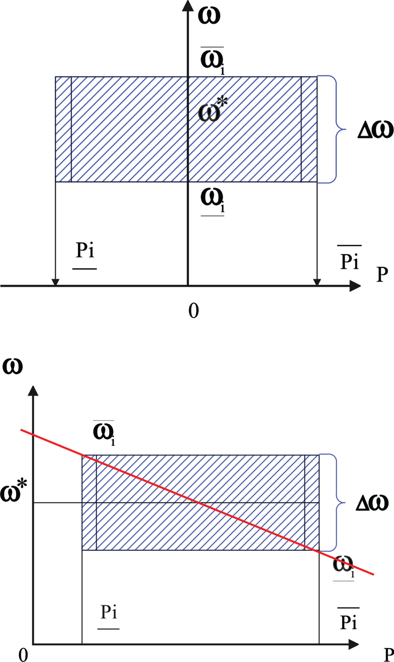
Sag control rules for DG and ESS. (a) Droop control curve of ESS. (b) Droop control curve of DG.
Next, aiming at the problem of active power distribution between DG and ESS in microgrid, the contents of droop control and secondary control in formula (3) are further studied. According to Kirchhoff’s Law, the power generation of each unit can be calculated according to
Among them, the deviation between bus voltage and expected voltage is very small when the system is stable, so w
ij
can be regarded as a constant,
The initial droop control is converted to:
Then, can get the system formula of each DG:
Similarly, considering the characteristics of ESS, can get the system formula of each ESS:
For the sake of simplicity of the model, the loss of charge and discharge is ignored here.
To describe this strategy, we define an auxiliary function variable Φ i = f i (P i ) to act as a bridge for power sharing between DG and ESS.
For each ESS, it is defined as [14]:
For each DG, there is actually no energy limit for energy storage, and the power output can only be positive, but a very large virtual capacity is set for unified control. Therefore, the auxiliary variable Φ i is defined as follows:
This paper chooses αi = 0.5.
In the second equation of formulas (8) and (9), use
When each DG system is linearized, the DG system in formula (7) can be rewritten as:
Among them, In order to correlate the control input u i (t) with the output y i (t), according to the input and output feedback linearization method, we obtain the following formula by finding the second derivative of y i (t):
Among them, ɛi (t) is the newly defined auxiliary control variable.
Next, we define that
At the same time, the control input u i (t) in the original system can be calculated by the following formula:
By a similar process, the ESS system represented by formula (8) can also be converted into a set of third-order systems as represented by formula (15):
Next, the detailed calculation method of feedback linearization is given.
The calculation method of DG system shown in formula (11) is as follows [15]:
First, y i (t) derives from x i (t):
Among them,
When the second derivative is found, u
i
appears, the derivative is end, and we directly set
The calculation process for feedback linearization of ESS system represented by formula (15) is as follows:
In the same step, y i (t) derives from x i (t):
Among them,
Since the coefficient of u
i
is still 0, it has been eliminated, so we continue to derive
Among them,
Since the coefficient of u
i
is still 0, we continue to derive
Among them,
At this point, after the third derivative is obtained, u
i
appears, and the derivative is end, and we set
The detailed control objectives is proposed:
In the formula, the first formula indicates that SOC in ESS is balanced in steady state. The second condition means that DG and ESS share power fairly according to their rated power and capacity.
It can be seen from formulas (13) and (15) that the state space orders of DG and ESS systems are different. In order to solve the problems of power distribution and SOC balance caused by different characteristics of DG and ESS, we introduce an auxiliary variable Fi (t) for each DG distributed generation to supplement the orders, so as to design distributed controllers conveniently. The dynamic formula of Fi (t) is given by the following formula [16]:
In this way, the two systems of different orders can be unified as:
By conjunction, can get:
Among them, a = [010; 001; 000] and B = [0; 0; 1].
At this point, the framework of the whole system is very clear, as shown in Fig. 2.
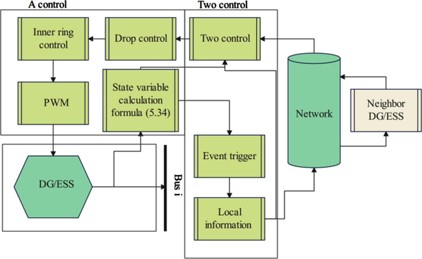
System frame diagram.
First of all, DG and ESS have the same sampling interval h, so for i ∈ S
DG
∪ S
ESS
, the time sequences of each sampling by the sampler is
After the original data is specified, we will specify the data sequence
Among them,
The dynamic items β
i
(t) is defined by the following formula [17]:
Scalars δ > 0 and matrices Σ > 0, W > 0 in trend terms will be found by LMI toolbox.
In this way, can design the event-triggered controller as follows to achieve the purpose of active power sharing and SOC equalization.
The controller gain K ∈ R1×3 will also be solved through LMI toolbox.
Lemma 1: If the communication graph G is connected, then there is a western matrix U satisfying U
T
U = I
N
, so that
Lemma 2: For a vector η (t) = col{ η1 (t) , …, η
N
(t) }, if there are matrices R and S that can make
In order to describe more concisely, we sort out the system model and make ξ (t) = col{ ξ1 (t) , ⋯ , ξ N (t) }. For t ∈ [mh, mh + h), there is d (t) = t-mh, so d (t) ∈ [0, h). By substituting formula (38) into formula (37), can get the final model of the system:
Among them, e (t) = col{ e1 (t) , ⋯ , e
N
(t) }. We define
By Lemma 1, we know that
The active power sharing and SOC balancing problems designed in the control objective are equivalent to the controller gain K in the design (37) and the event triggering parameters in formula (32), making the system (36) asymptotically stable.
Next, we prove the stability:
First, the positive definite Lyapunov function is constructed as the following formula, and its derivative is negatively definite, so that the system is stable.
For -h ⩽ s ⩽ 0W (t), η (s) = η (0) holds. Then, we find the derivative of W (t):
By using the event triggering mechanism (32), we know that
Among them,
Applying Lemma 2 and the above inequalities, can rewrite (38) as:
Among them,
Among them,
Among them, Ψ0 = [Ψ0] ij and
Therefore, Ψ0 ⩽ 0, and when Ψ (λ
i
) < 0, there is
In response to the sudden change in system load, a physical inverter experimental platform is built based on the low-voltage benchmark for experiments, and the results are analyzed.
The DC side uses a connected DC power supply, the switching device of the inverter bridge uses IGBT, and the output end uses an LC filter. After passing through the line impedance, it is connected to the PCC and connected to the common load. The distance represented by the line impedance has been marked in the figure, and in the experiment, every effort will be made to reproduce these data.
Due to the output characteristics of photovoltaic panels being approximately equivalent to a current source, the current source can be considered as a DC voltage source in parallel with a large capacitor within a certain range; For an energy storage battery array, multiple batteries connected in parallel can increase the output current, while multiple batteries connected in series can increase the output voltage, and can also be considered as a DC voltage source; The case where photovoltaic and energy storage are connected in parallel on the DC side can be directly regarded as a DC voltage source in a short time scale. So in the experiment, a DC voltage source was directly used as the power supply on the DC side of the inverter.
The physical structure of the fuzzy control system used in the whole experiment is shown in Fig. 3. The structure and line topology adopted are from Benchmark of low-voltage microgrid, which reproduces DG1 branch of Subgrid on the left side and runs in parallel with ESU at PCC.
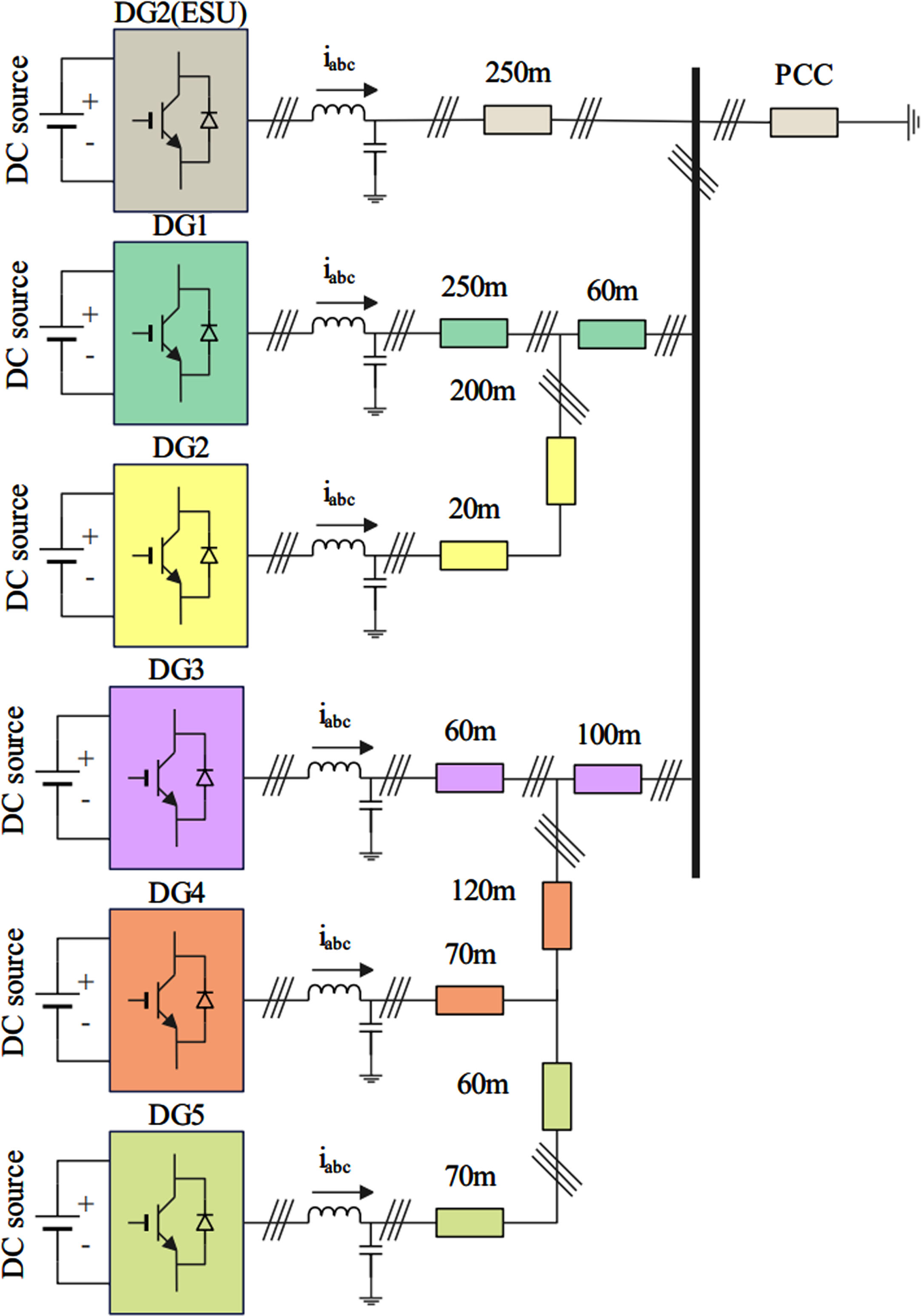
Overall physical structure of the system.
The DC side uses on-going DC power supply, the switching device of inverter bridge uses IGBT, and the output terminal uses LC filter, which is connected at PCC through line impedance and connected to common load. Because the output characteristics of photovoltaic panel can be approximately equivalent to a current source, the parallel connection of current source and large capacitor can be regarded as a DC voltage source in a certain range. For an energy storage battery array, multiple batteries in parallel can increase the output current, and multiple batteries in series can increase the output voltage, which can also be regarded as a DC voltage source. In addition, when photovoltaic and energy storage are connected in parallel on the DC side, they can be directly regarded as DC voltage sources in a short time scale. Therefore, the DC voltage source is directly used as the DC side power supply of the inverter in the experiment.
The hardware platform design needs to follow the three principles of safety, reliability, modularity, and universality. Based on the above principles, the experimental platform mainly includes modules such as drive circuit, control circuit, power circuit, protection circuit, auxiliary power supply, and detection. Among them, the control circuit, driver circuit (driver protection circuit), and auxiliary power supply modules are connected to the platform through interfaces for easy disassembly. Other sub modules such as output filtering, detection circuit, and three-phase bridge need to be welded to the main circuit board
When a system malfunction occurs, the circuit can be protected from most fault situations by blocking the PWM pulse. Therefore, the driver board not only includes logic control circuits, but also temperature detection and other links. The overvoltage and overcurrent detection link cannot be considered because the current limiting link is already set in the program.
The effectiveness of coordinated fuzzy control of hierarchical power balance is verified. The system topology used is shown in Fig. 3, where DG3 is a PV direct grid-connected control inverter, DG2 is an ESU, and the rest DG are VSG inverters. Due to the limited experimental conditions, the low-voltage Benchmark can not be completely reproduced, and the line impedance can only be reproduced as much as possible on the basis of multi-machine parallel connection, and the load quantity can be reduced at the same time. Firstly, the inertia-frequency response of VSG inverter is tested. ESU is not connected with the system, so the inertia-frequency response of VSG mode is compared with that of traditional droop control. In order to make the load change repeatedly and randomly under sudden increase and normal operation, the waveform of DG1 in Fig. 3 is collected as a representative, the experimental waveform of inertia-frequency response of traditional droop is shown in Fig. 4 (a), and the experimental waveform of inertia-frequency response of VSG mode is shown in Fig. 4 (b).
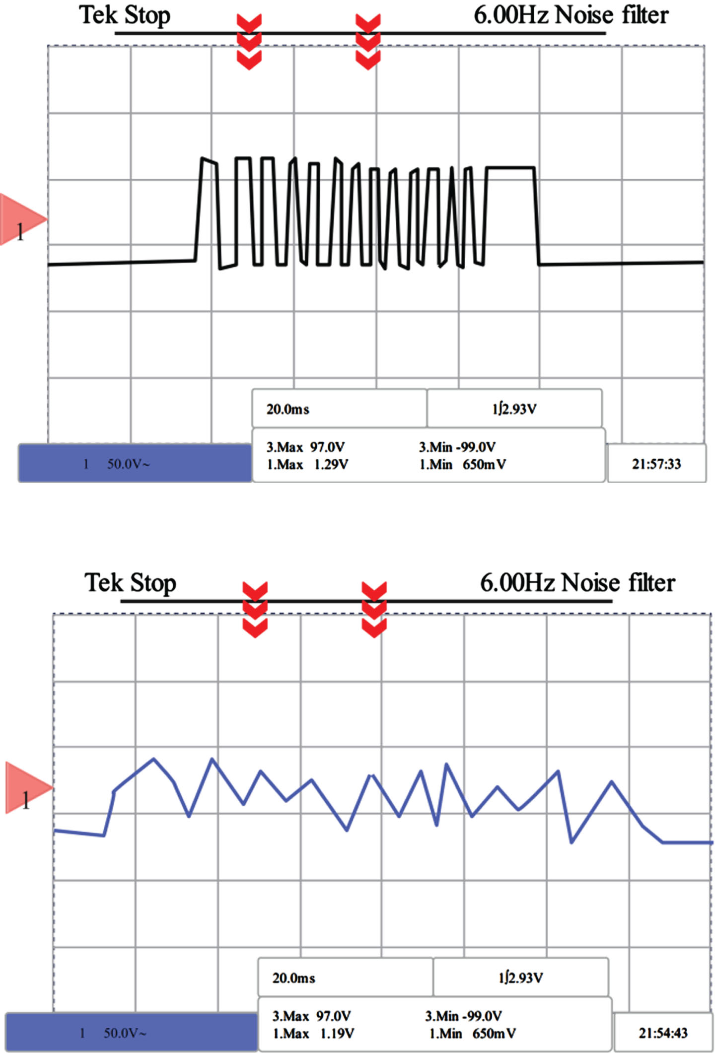
Frequency response. (a) Inertial-frequency response of conventional droop control. (b) VSG controlled inertial-frequency response.
Due to the limited parameters and load, the observation of the frequency change of the output voltage of photovoltaic inverter is not obvious enough in the experiment, so the absolute value of the difference between frequency and power frequency is taken as the output signal of DSP digital-analog conversion port. It can be seen from the figure that although the energy storage device (LC filter inductor) in the system provides a little inertia for the current (power) change of the system (inductor current can not change suddenly), it still can not change the problem of lack of inertia in traditional droop control. It makes the output voltage frequency of the inverter with traditional droop control fluctuate greatly with the load fluctuation when facing frequent load fluctuation, which is not conducive to the stability of the system.
The inertia-frequency response of VSG inverter is much better than that of traditional droop. When VSG is faced with random load fluctuation, because VSG control method provides enough inertia, the frequency change can be greatly slowed down, and the fluctuation range of frequency difference can be reduced to 0.5 times of the original, which proves that VSG control method is beneficial to the stability of primary frequency modulation of the system. The next is the overall operation of the system, ESU is connected with the system, and the instruction is set to 2A. When the multi-machine system starts running, the ESU must first calculate the phase of the current AC bus voltage with the help of phase-locked loop before it can work normally, so it is necessary to start the voltage source inverter first, and then start the ESU. The output voltage and current phase waveform and the output waveform after updating the current command are shown in Fig. 5 (a) and Fig. 5 (b).
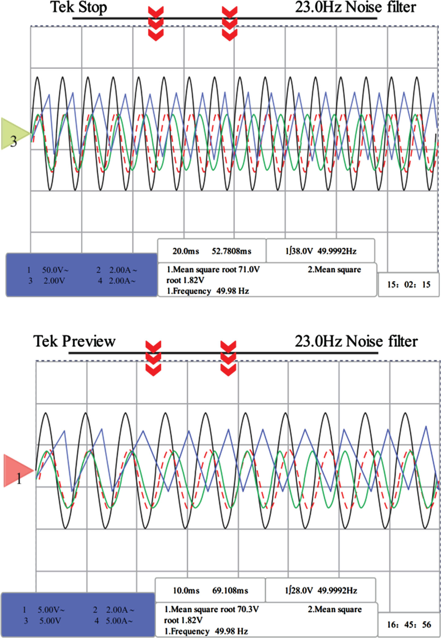
Output waveform. (a) Output voltage and current phase waveform. (b) Output waveform after updating current command.
Among them, Channel 1 waveform is the output voltage waveform of VSG photovoltaic inverter, Channel 2 waveform is the phase waveform of phase locked loop output, Channel 4 waveform is the output current of VSG photovoltaic inverter with an amplitude of about 2A, and Channel 3 waveform is the output current of ESU with an amplitude of about 2A. The ESU output current command is modified to 4A, and other parameters remain unchanged. To sum up, it can be proved that the system can operate normally under parallel connection, and ESU can also operate normally under the condition of instruction change.
Under the condition of normal operation, the switch of variable load box is used to simulate the load fluctuation. When the load increases by 50%, the output of photovoltaic inverter increases and the frequency decreases, which is reflected in the figure as the absolute value of the difference between the current frequency and the power frequency increases. After a period of time (15 min instruction update cycle simulating MGCC), ESU outputs current, which reduces the output current of photovoltaic inverter and picks up the frequency.
Figure 6 (a) measures four physical quantities: output voltage (channel 1), absolute value of difference between voltage frequency and power frequency (channel 3), output current (channel 4) and load current (channel 2) of photovoltaic inverter DG1. When the load suddenly increases by 50%, the power generation of each DG increases by 8.3%, the voltage-frequency difference of the system increases by about 2 Hz, the output current of photovoltaic inverter increases, and the dynamic process is about 0.3 s. At this time, ESU does not act. The reason is that MGCC cannot monitor the system in real time when the real system is applied. In practice, it can collect signals and update ESU instructions every 15 minutes corresponding to MGCC, so ESU adjustment is after sudden load change. Moreover, when the ESU starts to output current to the outside, the output current of the photovoltaic inverter decreases because the load current is unchanged, as shown in the signal of Channel 4 in Fig. 6 (a). At this time, the output current waveform of ESU is shown in channel 4 signal in Fig. 6 (b).
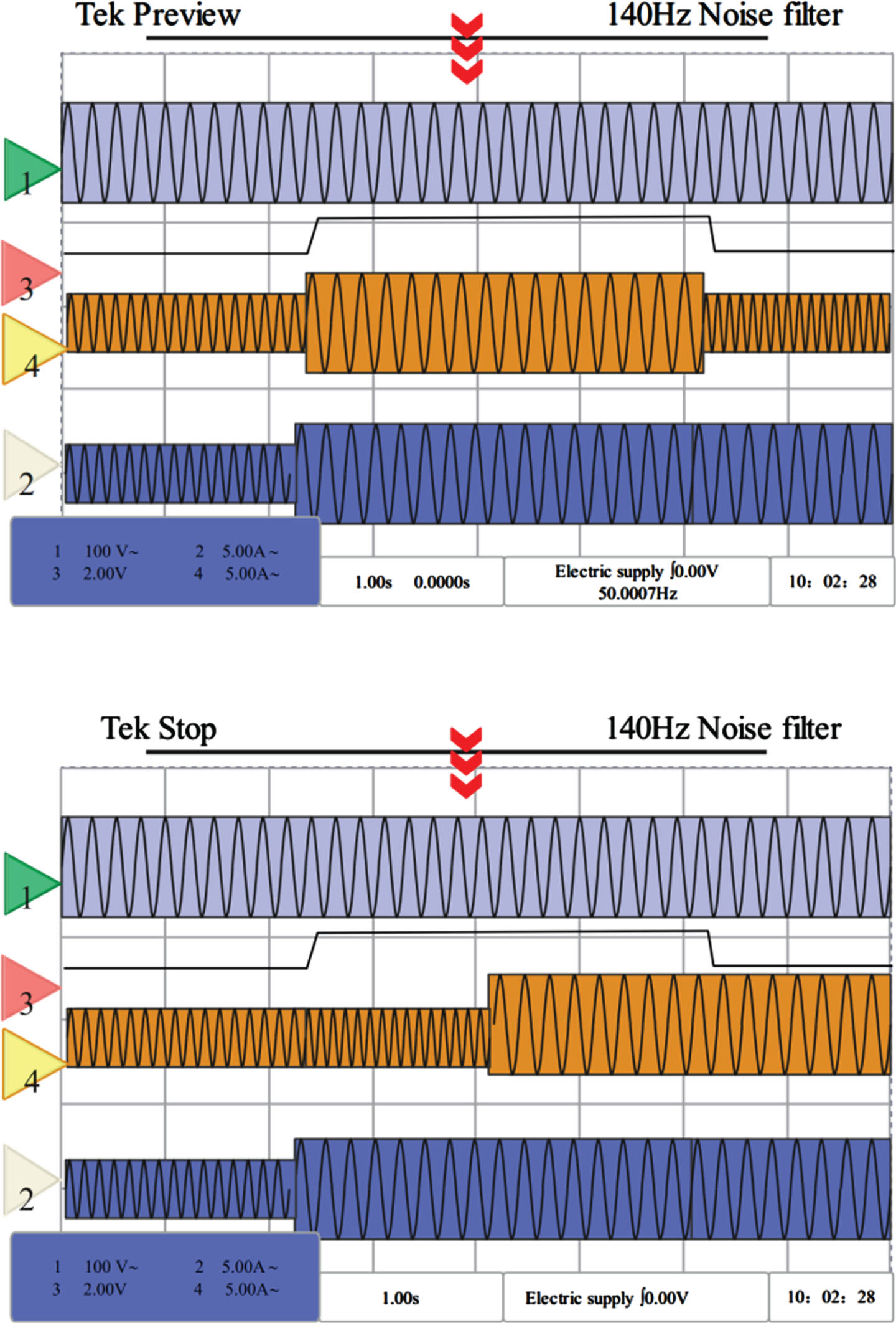
Waveform of layered control experiment. (a) Waveform of layered control verification experiment. (b) Waveform of layered control experiment (including ESU output current).
On the basis of the above experiments, a comparative experiment was designed to compare the hierarchical power balance coordination fuzzy control effect of the new energy microgrid model in this paper with reference [16]. A total of 20 sets of comparative experiments were conducted and evaluated in a percentage manner. Finally, the comparative results shown in Table 1 were obtained.
Comparative experimental results
From Table 1, it can be seen that the fuzzy control method proposed in this article has significant advantages over traditional models in hierarchical power balance coordination of new energy microgrids
From the above analysis, can see that the coordinated fuzzy control method of hierarchical power balance of new energy microgrid proposed in this paper has good effect.
This article applies fuzzy control method to the system and proposes a hierarchical control strategy based on event triggered communication. Each DG is treated as an agent, replacing the continuous actual output with state predicted values. Two different event triggering condition functions are designed based on the Lyapunov method for frequency and voltage, respectively. Each DG only communicates aperiodically with adjacent DGs at the time of event triggering, ultimately restoring each DG to the reference value provided by the virtual leader.
The experimental analysis shows that the hierarchical power balance coordinated fuzzy control method of new energy microgrid proposed in this paper has good effect.
The follow-up work that can be carried out in the future mainly includes:
For the energy balance problem under long time scales (such as 24 hours), the scheduling algorithm can be loaded into the upper controller based on the control method in this paper for energy scheduling. Therefore, energy scheduling is a future research direction that can be expanded.
This article only focuses on the control of a single microgrid, and the control issues of microgrid clusters need to be explored, such as how to reduce energy transfer between grids and plug and play connectivity between grids.
Footnotes
Acknowledgments
This work was supported by Key R & D and Promotion Projects (Key Scientifc and Technological Problems) in Henan Province (No. 232102240100).