
Abstract
Target station 1 (TS1) is currently in the implementation stage of a large sustainability project to continue future operation, in addition to making improvements to the neutron performance, ease of operation, and various other factors (J. Phys.: Conf. Ser.
Removal of the current TRaM systems support structure is discussed within this paper. This extraction comes with challenges; due to its abnormal size, the welded structure cannot simply be placed in a shielded flask and removed, it instead must be cut up into 2 sections inside the remote handling cell (RHC) (J. Phys.: Conf. Ser.
Introduction
The TS1 project is being executed to improve operation and performance by replacing the TRaM along with all services supporting this. After around 30 years of operational experience for this target station, it was recognised where a number of improvements could be made [2]. For example, equipment such as the methane moderators are replaced twice a year owing to reduced performance and potential blockage, and the new design for the reflector assemblies can be simply split into two, enabling easy access for the remote handling arms to the moderators and a smoother operation [1].
A new frame manufactured from stainless steel plates bolted together will support the TRaM. This assembly is modular to simply install future upgrades, and also to consider the difficulty of end of life disposal [4]. An image of this new design compared with the old is shown in Fig. 1.
Removal of the old equipment is a logistical and operational challenge. Every other component has previously been extracted through the remote handling cell trap door (see Figs 2 and 3). However, the current cantilever beam support frame has not (so is highly activated), and is a welded structure too large to fit through the door. The remote handling cell roof could open up for removal, though it would be a difficult operation keeping radiation levels down for staff and the surrounding area, especially in the event of a crane failure. Cutting it into sections within the cell to fit it through the trap door is much safer as the tunnels below are heavily shielded and easily evacuated. Therefore, the latter method has been chosen and is discussed in this report.
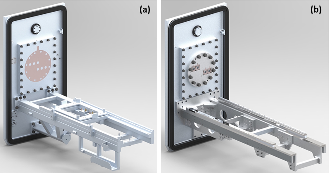
(a) currently installed TRaM support frame, (b) new design of the TRaM support frame.
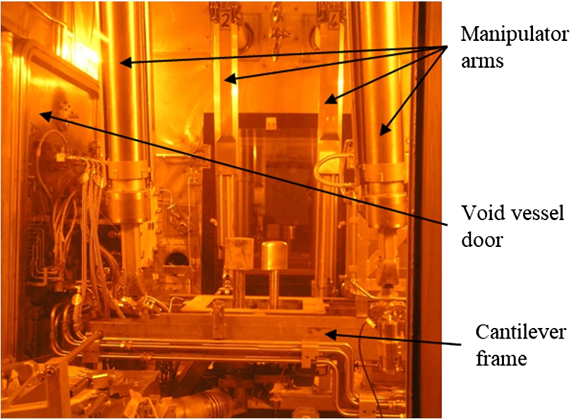
Image of the RHC.
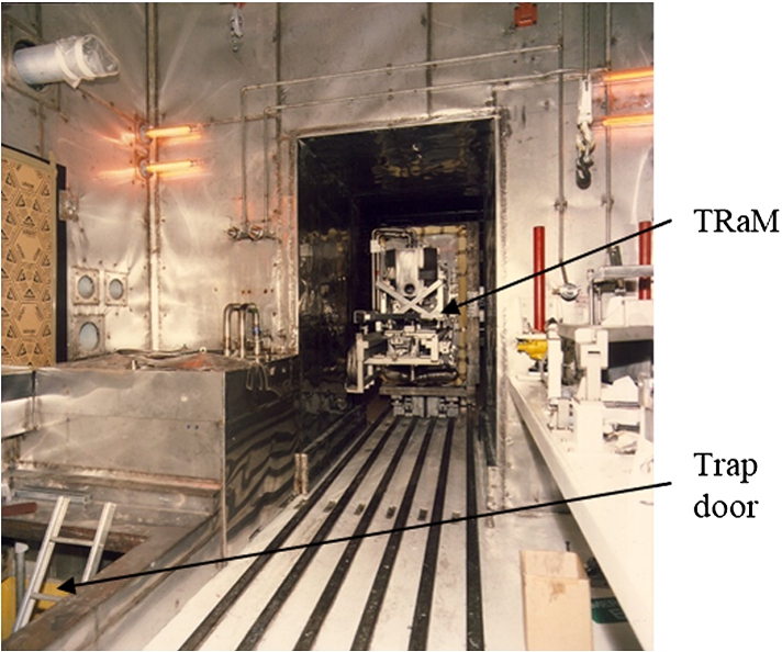
Image of the TRaM and trap door.
A large variety of concepts were developed as methods for cutting up the cantilever beams. One of these was hydraulic cutters which are used in emergency rescue operations by the fire service. These will be used to cut up smaller structures on the TRaM, but the larger model required for the thicker support structure cantilever beams is very expensive, difficult to power, and would be challenging to manoeuvre around the relatively small remote handling cell.
One company proposed using a jig to hold steel rope under tension around the cantilever beams, and producing a sawing motion via a drive system to cut through them. This was dismissed as it was extremely costly and would spread the radioactive swarf around the remote handling cell, creating a problematic clean-up operation.
Other unconventional methods were considered to cut up the cantilever support beams, including thermal cutting and abrasive water jets. These were quickly rejected however, as fumes from the thermal cutting torch would contain particles of the activated cantilever beam, which could contaminate and damage the ventilation in the remote handling cell. Using a water jet would produce a contaminated slurry which could leak across the cell and become challenging to dispose of. Consequently, much more equipment would be required to contain these issues, plus more radioactive waste would require disposal.
After widespread consideration, it was decided to use a conventional powered saw with a jig to mount it onto the support structure. A circular saw, horizontal bandsaw, and a reciprocating saw were tested by attempting to cut up a mock cantilever beam. The circular saw cut through well but produced a wide spread of swarf, and the reciprocating saw could not be suitably sourced. Therefore, the bandsaw was chosen as it also produced a small spray of swarf and cut through smoothly with small vibrations or blade bending. Compared with other methods, using a standard commercial bandsaw is also beneficial for spares.
Initial design with further testing
Now that the type of saw was chosen, the accompanying kit needed designing to allow remote handling arms to install and operate it. A gravity driven hydraulic piston was designed underneath the bandsaw, in a jig that caused the bandsaw to rotate downwards towards the vertical during cutting. This jig was designed to lower onto a set of locating pins, in a different position for either side of the frame so that the cut was in line across the frame. An appropriate feed rate for the cylinder was worked out to try during testing.
Due to the activated environment, the cut has to operate under dry conditions. This means the blade has to run much slower than normal, to prevent build-up of too much heat. It was decided to test the lower speed setting of 35 m/min and if need be, add an inverter to slow the motor further. A bimetal blade was chosen over Tungsten Carbide Tipped blade as it has a mix of hard and soft teeth so is more flexible, a quality important for this dry cut. For a first attempt in the test, an estimate of the appropriate TPI (teeth per inch) of the blade was calculated, based on the beam cross-section.
These calculated conditions were tested on the mock up cantilever beam, using the designed jig mounted on a temporary frame (see Fig. 4).
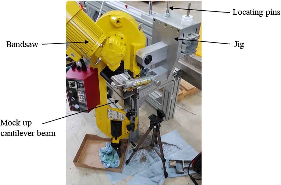
Test rig for further testing on the bandsaw concept and initial designs.
The cut was completed 3 times using the same blade. Results were promising; the blade remained in good condition after each cut and the feed rate was fine tuned to provide a cutting speed which produced minimal vibrations and jumps on the saw. Testing also proved that a swarf curtain was not required like previously thought as the spray was small, therefore a tray could catch most of it.
Testing proved the concept could work, but more components still required designing.
Firstly, a mount for the bandsaw to attach onto one end of the support frame during cutting was designed. This included capability to adjust the position of cut easily using remote handling arms, by turning a leadscrew to slide the bandsaw and tightening some bolts to lock it into position (see Fig. 5). It was also designed to be modular for easy disassembly and segregation for disposal after use.
Next, a lifting eye was designed, which rested just above the centre of mass so that when it is lifted by the crane in the remote handling area it stays upright. This assembly needs to be lowered onto locating pins for the cut on one side, then lifted, rotated and placed on different pins for the second cut.
During cutting the frame could pinch the bandsaw blade from the weight of the end section, or any residual stresses. To prevent this, a scissor lift trolley will be placed underneath the free end of the frame and lifted until support is provided. A plate will also be bolted across the first cut utilising existing bolt holes, to assist in locking the beam halves in position.
Reliability is an extremely important requirement for this project, as it would be difficult to change the operation mid-way through. Adjustable positions have been designed where possible on components, however, only by testing is it possible to safeguard that the bandsaw blade will not break. For the unlikely case that it does break, it was considered to design tooling to make it possible to change the blade within the remote handling cell. In the end, it was deemed cheaper and easier to purchase spares for the bandsaw instead and to make a total replacement in the event of a failure.
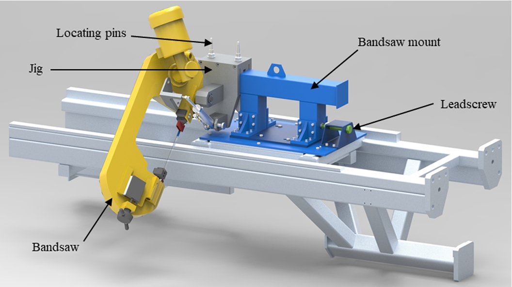
Bandsaw mount with adjustable position from the leadscrew (green) to the right.
Design work is underway for lifting the cut up frame into a shielded flask. A lifting eye has been designed for the end half of the cut support frame, which simply attaches onto existing features and leads to a short operation (see Fig. 6). Once the end section is lifted, it will attach onto the other section in the upright position using the bracket shown in Fig. 7. This assembly will then be lowered into a flask and extracted.
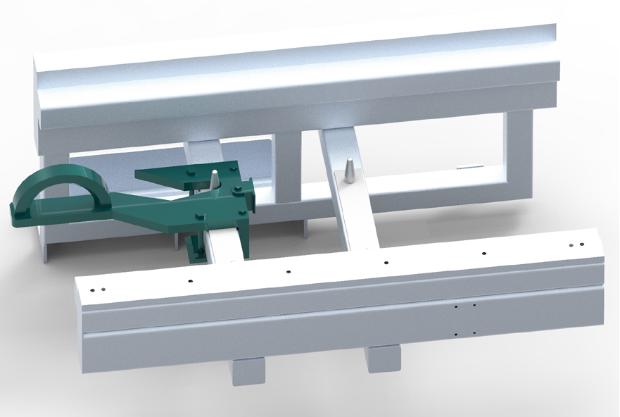
Easily attached lifting eye for one of the cut beam sections, using already available pins.
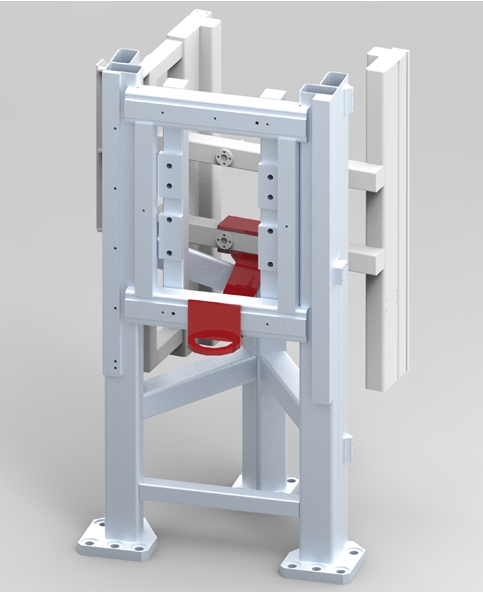
Bracket design to clamp TRaM frame cut sections together, to be reliably placed into a flask.
There is still work to be done on this project, but this solution looks like a viable option. A lifting eye is required for the other half of the cut up support frame, and there are ideas for a few components which make the operation of the bandsaw easier using the remote handling arms.
Once the last components have been manufactured, the whole solution will be tried using a mock up remote handling cell, described in [3]. Here the replica of the current support frame will be placed within the area, the bandsaw mount attached, and sawing operation completed using the crane and arms just like the real job. This will bring any potential problems to the surface and will provide a practice run for the operation staff.