



Abstract
The linac and the 3 GeV rapid-cycling synchrotron (RCS) at the Japan Proton Accelerator Research Complex (J-PARC) were designed to provide 1-MW proton beams to the following facilities. Due to the improvement of the accelerator system, we accelerated a 1-MW beam with a small beam loss. The lack of anode current in the radiofrequency (RF) cavity, rather than beam loss, limits the RCS beam power. Recently, we developed a new acceleration cavity that can accelerate a beam with a low anode current. This new cavity enables us to reduce the requirement for the anode power supply and accelerate a beam of more than 1 MW. We considered how to achieve beam acceleration beyond 1 MW. So far, a beam of up to 1.5 MW is expected to be accelerated after replacing the RF cavity. We also studied to achieve an up to 2 MW beam in J-PARC RCS.
Introduction
The Japan Proton Accelerator Research Complex (J-PARC) is a multipurpose facility that conducts scientific experiments [2]. The accelerator complex comprises a 400 MeV linac, a 3 GeV rapid-cycling synchrotron (RCS), and a 30 GeV main ring (MR) synchrotron. The linac and the RCS are proton drivers for muon and neutron targets in the Material and Life Science Facility (MLF), respectively. Figure 1 shows the layout of the J-PARC facilities. From the start of the accelerator operation, we continued beam commissioning and improvement studies of the accelerators to achieve a high-intensity and stable operation. The linac and the RCS have successfully accelerated a 1-MW beam with minimal loss [15]. Furthermore, accelerator operations for neutron and muon users have been sufficiently stable [16]. J-PARC has upgrade plans, such as shortening the MR cycle [5] and the second target station for neutron and muon users [19]. We satisfied the requirements of these upgrade paths by considering how to achieve a beam acceleration beyond 1 MW. This paper summarizes the current status of the linac and the RCS. It also presents a scenario for increasing the RCS beam power.

Layout of the Japan Proton Accelerator Research Complex (J-PARC) facility.
Linac
The J-PARC linac accelerated a nominal peak beam current of 50 mA to 400 MeV for the RCS. A 60 mA H− beam is produced in the ion source for user operation [7]. During the accelerator study, we attempted a higher peak current operation from the ion source and extracted beams higher than 72 mA. Moreover, the lifespan of the ion source was gradually extended. In RUN#89 (Jan. 2022–Jul. 2022), the continuous operation time of the ion source reached 4,001 hours. (5.5 months). The final goal is to continuously operate for more than seven months, approaching the full J-PARC user operation period of one year.
The trip rate of the Radio-Frequency Quadrupole linac (RFQ) was approximately 10 times daily during user operation in FY2022. The trip almost occurs singly and is rarely consecutive. In the present operations, we do not stop the beam with a single trip in the RFQ; therefore, this event has little effect on availability. This situation is similar to before.
In 2022, an RF trip due to discharge occurred frequently in the third drift tube linac (DTL3). At the most, there had been more than 30 trips per day. The vacuum pressure increased when the discharge occurred. We prepared a CCD camera attached to the viewport in front of the RF coupler and observed that the ceramic window of the RF coupler flashed. This phenomenon indicates that the discharge at the vacuum-side surface of the ceramic window in the waveguide caused the DTL3 to trip. We replaced the ceramic window of the DTL3 with a new one during the spring maintenance period at the end of March 2023. After replacing it, the discharge in DTL3 subsided drastically (2–5 trips per month).
After the Great East Japan Earthquake, some separated-type DTL (SDTL) cavities could not be excited with the designed RF power because of the multipactor effect. The high-power RF cannot be stably supplied to the SDTL cavity due to increased reflected power near the operating power region for six of 32 SDTLs. Due to the earthquake, the cavities were exposed to air and contaminated, and one-side multipacting conditions were established at the cavity walls near the operating power for these six cavities. Therefore, we consider that this problem is due to the multipactors on the contaminated surface of the cavity. We washed the inside of these cavities with acetone or acid cleaning. Three cavities (SDTL#05B, #06A, and #06B) were cleaned with acetone in 2015 and 2016, and their unstable regions disappeared. In 2021, during the summer shutdown period, the SDTL05A cavity, one of the most unstable cavities of the remaining ones, was cleaned with dilute hydrochloric acid. Since then, the unstable region has disappeared. Other unstable cavities of SDTL04A and SDTL04B remained and underwent with acid cleaning during the summer maintenance period of 2022. Finally, there are no RF reflections due to the multipactor in these cavities, ensuring the stable excitation of all SDTL cavities at their designed operating power [1]. The number of trips for all annular-ring-coupled structure (ACS) cavities was less than once per day, indicating that the operation of the ACS cavities was more stable compared to other cavities.
RCS
Figure 2 shows the variation in RCS output power with time. In recent years, the output power has increased to 100 kW per year [16] and reached 800 kW in April 2022. Subsequently, the beam current was maintained; however, the total number of protons on the neutron target effectively decreased due to the shortened MR operation cycle. The beam power in the MR was augmented by replacing the power supplies of the MR magnet system and reducing the MR operation cycle in the fast extraction mode from 2.48 to 1.36 s. This shorter MR cycle diminished the operational duty of the MLF from 58/62 (∼93.5%) to 30/34 (∼88.2%), consequently reducing the number of protons on the neutron target. Finally, the beam power of the MLF has been sustained at 800 kW until JFY 2023. Unfortunately, one of the transformer-rectifier assemblies in the RF system malfunctioned in June 2022 [16]. After this event, we could only use 11 RF cavities and accelerate 800 kW beams under this condition. We plan to restore this assembly by the end of JFY 2023.
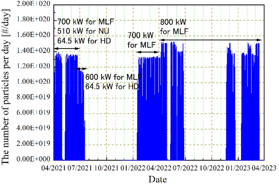
Change in RCS output power with time: NU means the neutrino experiment, and HD means the experiments in the Hadron hall.
The operational status of the linac and the RCS was stable, and no significant incidents have occurred in recent years. Figure 3 summarizes the availability of neutron and muon users. In the last five years, no severe issues have occurred in the linac, the RCS, or the MLF. In particular, we achieved over 95% availability in the previous four years.

Availability of the MLF facility.
Linac
Beam studies have been conducted to mitigate beam loss and confirm the feasibility of further high-intensity operations because of the demand for downstream facilities. One issue with the linac is the worsening transmission at the front end. To understand the reason for this, we performed a beam study at the upstream beam transport line, MEBT1, which is essential for mitigating the increase in emittance during the DTL. The beam distribution was measured using the Q-scan method using a wire scanner monitor and a quadrupole magnet. Figure 4 shows the measured and the simulated results in the x-direction. The measured profile matched the simulation well, and the observed emittances were consistent with the anticipated parameters. Based on these findings, the beam dynamics within the DTL are being investigated.
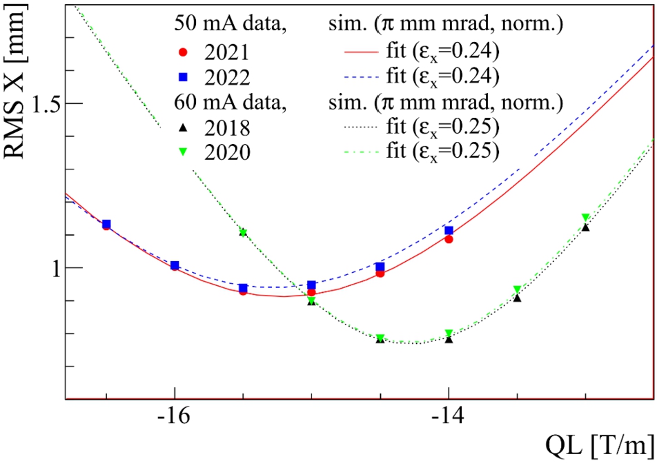
The measured and simulated beam profile widths: the circles, squares, and triangles are the measured results; the solid and dotted lines are the simulation results.
We also investigated the cause of beam loss among the high-energy parts of the linac. Residual doses have been observed from SDTL to ACS, with a corresponding kinetic energy of the accelerated particle of 50–400 MeV. We conducted numerical simulations under more realistic conditions, such as gas-stripping and intrabeam-stripping effects. The simulation results qualitatively reproduced the residual dose distribution. To date, these effects have been the primary causes of the beam loss. We will continue to conduct further studies to reduce these losses.
We continued the beam study to reduce the beam loss further. One of the remaining sources of beam loss is the intrinsic sextupole field component in the injection chicane bumps (CBs). The sextupole field drove the

The study results with and without reduced CB fields: the green line shows the loss signals at the original CB field strength, and the purple line indicates the loss signals at 80% CB field strength.
We also optimized other parameters (the transverse and longitudinal painting patterns and betatron tunes) and achieved more than 80% beam loss mitigation at 1-MW beam operation compared to the operation in 2020. The residual beam loss was less than 0.05%, even at 1-MW beam power, and was dominated by foil scattering. We will attempt to reduce the foil size further.
Motivation
The RCS beam power is currently limited by the lack of anode current in the RF cavity system rather than beam loss. Recently, we developed a new accelerating cavity to accelerate beams with a low anode current. This new cavity enables us to reduce the requirement for the anode power supply and accelerate a more than 1-MW beam. We considered how to achieve beam acceleration beyond 1 MW.
Demonstration results beyond 1-MW beam power
We studied the potential of the RCS beyond 1-MW beam power [4]. Figure 6 shows the results of the more than 1-MW beam study. Since the capacity of the anode power supply of the RF system was insufficient, we could not accelerate a beam larger than 1 MW in the system. The RF bucket is distorted because of the wake voltage caused by the high beam current of more than 1 MW, and all the beams are lost at the middle acceleration stage. Therefore, we accelerated the beam to only 0.8 GeV energy, and all beams were extracted at this time. Figure 6 shows no significant loss after a 1.5-MW equivalent beam current injection and partial acceleration.

Experimental results: circulating beam intensities from injection to extraction [4].
The RF system must be improved to accelerate a more than 1 MW beam. The J-PARC ring RF group recently developed a new cavity structure to accelerate a beam that is more than 1 MW [18]. The conventional RF cavity is driven with a push–pull operation mode, where two vacuum tubes feed the RF power in the both upstream and downstream of the acceleration gap. This configuration has the advantage of suppressing a higher-harmonic distortion without beam acceleration and shortening the cavity length. However, multiharmonic RF excitation causes a severe imbalance in the required anode voltage and a deficiency in the anode current. Therefore, a new cavity (single-ended cavity) was developed. In this new system, only the downstream of the gap was excited [17]. This configuration reduced the input current in the cavity. The new cavity was installed in the RCS tunnel during the summer shutdown period in 2021. Finally, we attempted a 1-MW beam acceleration with this new cavity and confirmed that it can accelerate a 1-MW beam with ∼60% less power consumption. This result indicated that the new cavity could accelerate higher beam currents and reduce the power consumption of the current user operation. We have started mass production of the new cavity. In the present schedule, we will complete the replacement work by 2028. After the replacement, we will attempt more than 1 MW beam acceleration in the RCS.
Scenario beyond a 1-MW beam
Requirements for the linac
A prime consideration is to increase the injection beam current from the linac. Table 1 summarizes the relationship between the RCS output power and the linac parameters. A beam with a peak current of 60 mA and a macropulse length of 0.6 ms was accelerated and injected into the RCS. If the RCS can further accelerate this beam to 3 GeV, we can achieve an output power of approximately 1.5 MW.
Some parameter choices in the linac are available to achieve a beam power exceeding 1.5 MW in the RCS. For the RCS, a higher peak current is preferable to reduce the macropulse length and the number of foil hits. However, we have never accelerated a peak beam exceeding 60 mA in the linac, which appears somewhat challenging, requiring additional study time. For the longer macropulse, we already encountered beam dynamics in the linac. Therefore, we can expect an operational condition with a peak current lower than 60 mA. However, extending the RF excitation duration and reinforcing the RF system are necessary. A peak current of 80 mA and a macropulse length of 0.75 ms are the targets for achieving up to a 2-MW equivalent beam injection in the RCS.
Relation between the RCS output power, the linac peak current, and the macropulse length
Relation between the RCS output power, the linac peak current, and the macropulse length
The other items are required to reinforce the RCS to achieve more than 1 MW beam acceleration. In the RF system of the ring, replacing the cavity and reinforcing the amplifier chain are also required.
To inject a longer macropulse beam, we must extend the duration of the field patterns of the injection magnets. The requirements for the correction quadrupole and the sextupole magnets were evaluated using particle simulations.
Even with a beam power of 1 MW, beam instability occurred with poor parameters (e.g., betatron tuning and the chromaticity correction pattern) [11]. The transverse impedance of the extraction kicker magnets is the dominant source of RCS instability [10]. We developed a new damping system to suppress this [12]. The simulation results indicated four damping modules are required to stabilize the 1.5-MW beam. We installed two damping modules, and the other two are under construction.
We used a hybrid-type thick boron-doped carbon (HBC) foil for the charge exchange injection [20]. It was developed in the KEK laboratory [13]. We confirmed that it can maintain its function under 1 MW continuous operation and intermittent 1.5-MW equivalent beam injection. Recently, we developed a pure carbon foil instead of an HBC [6], exhibiting a performance similar to that of the HBC. We will evaluate the HBC and pure carbon foils for higher-power operation.
Perspective of the beam manipulation beyond a 1-MW beam intensity
The numerical simulations indicate that the RCS can accelerate an equivalent beam to less than 2 MW [3]. The space–charge effect caused by a high-intensity beam of more than 2 MW causes an excessive tune shift, resulting in a large amount of beam loss. We mitigated the space–charge effect by applying a dual-harmonic RF operation for longitudinal beam manipulation to obtain a flatter beam [14]. The second-harmonic RF helps flatten the longitudinal beam distribution in the dual-harmonic scheme. This scheme helps achieve a 1-MW beam with a sufficiently low loss condition but not enough for a more than 1.5-MW beam. Recently, we studied the triple-harmonic RF operation for high-intensity beam acceleration [8]. Figure 7 shows the bunching factor (BF) simulation results with the dual- and triple-harmonic schemes. BF is the peak current divided by the average current, and a higher BF indicates a flatter and low-peak density beam. In these calculations, a beam power of 1 MW is assumed.
The BF is approximately 0.3 during the first 300 turns in the dual-harmonic case. However, it improved to more than 0.4 for the triple-harmonic operation, which would help with a more than 1.5-MW beam acceleration. Furthermore, we achieved further beam loss reduction in the 1-MW beam condition. These efforts will help achieve more than 1-MW beam acceleration.

The longitudinal beam simulation results for the dual- and triple-harmonic operations [8]: the top, middle, and bottom figures show the bunching factor (BF), momentum filling factor, and
The J-PARC linac and the RCS exhibited almost continuous and stable user operation with an 800-kW beam. Previous study results indicated that the beam loss is sufficiently small, even with a 1-MW beam power; thus, we increased the beam power after recovering the RF system in the RCS.
We demonstrated the RCS’s potential beyond 1 MW of power. The MLF and the MR, the facilities that follow the RCS, have upgraded plans to maximize deliverables. Evaluating the maximum RCS beam power is critical for considering the upgrade paths.
In this plan, we will replace all cavities with new ones by 2028. We investigated the requirements for a 1.5-MW beam acceleration. Currently, a list of items that require improvement beyond 1-MW beam acceleration is being developed in the RCS. We will work on a detailed study of increasing the peak current and macropulse length of the linac. To reduce the burden of the linac as much as possible, RCS plans to study an injection scheme with an extended intermediate pulse length. Finally, we will prepare to conduct beam acceleration tests at the highest possible intensity in 2028. By combining the increase in the linac peak current and the extension of the injection pulse length for the RCS, we will attempt up to 2 MW beam acceleration.