
Abstract
Modelling and verification of complex systems including mobile agent-based software systems are a painful task, because of different constraints such as mobility and security which must be taken into account to build correct software. This is what strongly hindered their evolution in preceding years in comparison to the success enjoyed by object oriented systems. UML has contributed largely in the success of object oriented systems. Mobile UML is a proposed extension to UML for modelling mobile agent-based software systems, and it inherits the problem of no precise formal semantics due to its semi-formal nature. This paper aims to build a semi-formal/formal framework that allows modelling and verification of mobile agent-based applications. First, a mobile agent-based application is modeled using Mobile UML diagrams. Then, an automatic translation of these diagrams to
Introduction
Mobile agent-based software systems have shown multiple advantages in a wide range of domains such as: network management, electronic commerce, energy efficiency, grid computing, distributed data mining, wireless multimedia sensors, and multimedia [22]. In fact, the mobile agent paradigm provides multiple benefits, such as its heterogeneous nature, it operates asynchronously, it adapts dynamically and reacts autonomously to changes, which could overcame and solve several problems in different fields. Mobility is the novel concept of the paradigm; it is the agent capability of moving from a host to another where it continues its execution in order to achieve a task. The modelling and verification of the behaviour of such systems is still a tough task, because mobility produces complicated dynamic reconfiguration of the system in question during its execution.
Having an appropriate approach, that used to model and verify such systems during the design phase, should enhance building correct software which respond to the user’s requirements. Multiple attempts for developing a rich expressive language for these systems are performed in the literature, such as Mobile UML (M-UML) [25]. M-UML is an extension of UML [21] that deals with modelling mobile agent-based applications, by covering the mobility aspects which is considered as the main concept inherent to such systems. M-UML has no formal semantics, so it cannot support formal analysis or verification of their models. On the other side, the
This work is part of a project that aims to provide a complete practical integrated approach, which can be used to specify and verify automatically mobile agent-based software systems. Our previous works include a state of the art of different methods and tools that have been developed for modelling mobile agent-based software systems [4]. This last led us to propose a partial contribution that consists on using graph transformation for mapping mobile statechart diagrams to
In contrast to these works, the idea of multi-paradigm modelling [26] is adopted in the present paper for modelling and verifying mobile agent applications. Actually, two formalisms are used; M-UML and the
This work plans to generate a very rich description of behaviour of every system modelled in our framework. To reach this goal, and in order to maintain coherence and consistency between different diagrams, we have chosen a driving type of diagrams (in our case, the mobile statechart diagram) and we add necessary information about the system from the other types of diagrams (in our case, the mobile class diagram and the mobile collaboration diagram). A mobile statechart-driven approach provides a detailed description compared to the mobile collaboration-driven approach, actually, the behaviour of each agent is specified in satisfactory details using the first approach.
Regarding other diagrams, the class diagram brings interesting information about the relation between agents which belongs to its classes, and also more details about their behaviour in its methods. The collaboration diagram brings interesting information about communication between the agents (statecharts). The details are given in Section 4.3.1.
To implement the framework, the AToM
The rest of the paper is organized as follows. Section 2 exposes multiple related works. Section 3 presents a background of M-UML,
Literature review
The literature is filled with the approaches which try to give formal semantics to UML and its extensions using formal methods in the purpose of enabling automatic verification. In fact, we have already made in [4] a systematic discussion on the literature about techniques and approaches of modelling and verification of mobile agent-based software systems. A taxonomy is given and the major issues of the research area are identified such as mobility modelling. The authors classified existing proposals in three large categories: UML-based Approaches, Formal Approaches and Hybrid Approaches. A comparison framework was developed also. The study concludes by considering the category of hybrid approaches as the most promising techniques, because adopting the combination of visual approaches and formal approaches provides great benefits including intuitive manipulation and analysis enabling. The interested reader can refer to [4] for the details of the study. We recall here some contributions, which belong to the category of hybrid approach and which are very close to our work either in using
Ragarding the use of
Ragarding the use of the Multi-paradigm tool AToM
Our work, contrary to all preceding contributions, tackles a subset of mobile UML (i.e. mobile applications), uses three types of diagrams at once and derives
The semantics of UML diagrams which include mobility were handled in [2, 16]. The authors in [2] have used meta-modelling and graph grammars to propose an approach for the automatic transformation of mobile UML statechart diagrams to nested nets. The purpose is enabling modelling and analysis of mobile agent-based software systems. The same objective has encouraged the authors in [16] to propose an approach, based on meta-modelling and graph transformation, to transform mobile activity diagrams into nested Petri nets to deal with another modelling view of such systems.
Although the two last contributions are very beneficial and interesting, we had some concerns on the target formalism adopted, i.e. Nested Nets formalism, which does not offer tools to enable automatic analysis and verification, besides its limits in providing explicit modelling of mobility in comparison with the
Preliminaries
Mobile UML (M-UML)
Mobile UML (M-UML) [25] is an UML extension which is expected to deal with the modelling of mobility requirement in mobile agent-based applications. M-UML covers all aspects of mobility at different views and diagrams of UML. We are concerned in this work with three diagrams among them; the mobile class diagram, the mobile collaboration diagram and the mobile statechart diagram. A description of these diagrams is given here.
A mobile class diagram (see the example in Fig. 4b, its description will be given in Section 5.1) represents the internal static structure of the mobile software system by showing its classes and the relationships among them. In short, this diagram adds the notions of mobile classes (from which mobile agents are created), affected classes (containing behaviour, i.e. methods that are communicating with mobile agents), and remote classes (containing behaviour, i.e. methods that are communicating with remote mobile agents).
A mobile collaboration diagram (see the example in Fig. 5b, its description will be given in Section 5.1) is an interaction diagram that shows the interaction behaviour of agents using a sequence of exchanged messages. In short, this diagram adds notions of local interactions (occurring at the same platform), remote interactions (one or both of the two interacting agents are away from their platform) and self-loop interactions (to represent the mobile agent returning to its original platform).
A mobile statechart diagram (see the example in Fig. 3b, its description will be given in Section 5.1) describes the behaviour of an agent in terms of state change in different platforms. In short, this diagram adds the notions of mobile states (states reachable by the agent far from of its base platform), mobile transitions (transitions between two states which are reachable by the agent while they occur at two different platforms), remote transitions (occur when the agent interacts with another agent remotely to reaches a state), and return transitions (which used to represent the mobile agent returning to its base platform by reaching a state on it).
-calculus
The
Furthermore, the following shortcuts are defined:
The semantics of
Table 1 recapitulates the reduction operational semantics of the
Graph grammars in AToM
AToM
Reduction semantics of the
-calculus
Reduction semantics of the
Taken the example of a sample graph grammar in Fig. 1, to improve general understanding of graph transformation. The graph grammar GG is composed of two rules R1, R2, which are applied on a source graph to generate a target graph. A source graph is composed of linked circles and hixagones. A target graph is composed of parallelograms and trapezes. The rule R1 has a circle node as LHS and a parallelogram node as RHS, its priority is one, so it will be the first rule in execution. The rule R2 has a hixagone node as LHS and a trapeze node as RHS, so it will be the second rule in execution. Conditions before each rule and the actions after will be written in syntax of the transformation engine. Thus, applying GG on each source graph provided composed of circles and hixagones, we will obtain at the end of the execution a target graph composed only of parallelograms and trapezes.
Graph transformation principle.
The mobility workbench MWB [27] is a tool developed to enable the automation of the analysis of
The proposed modeling and verification framework
The architecture of the framework
In the framework, a combined meta-modelling and graph grammar approach is adopted to build an integrated tool using AToM
The architecture of the developed framework.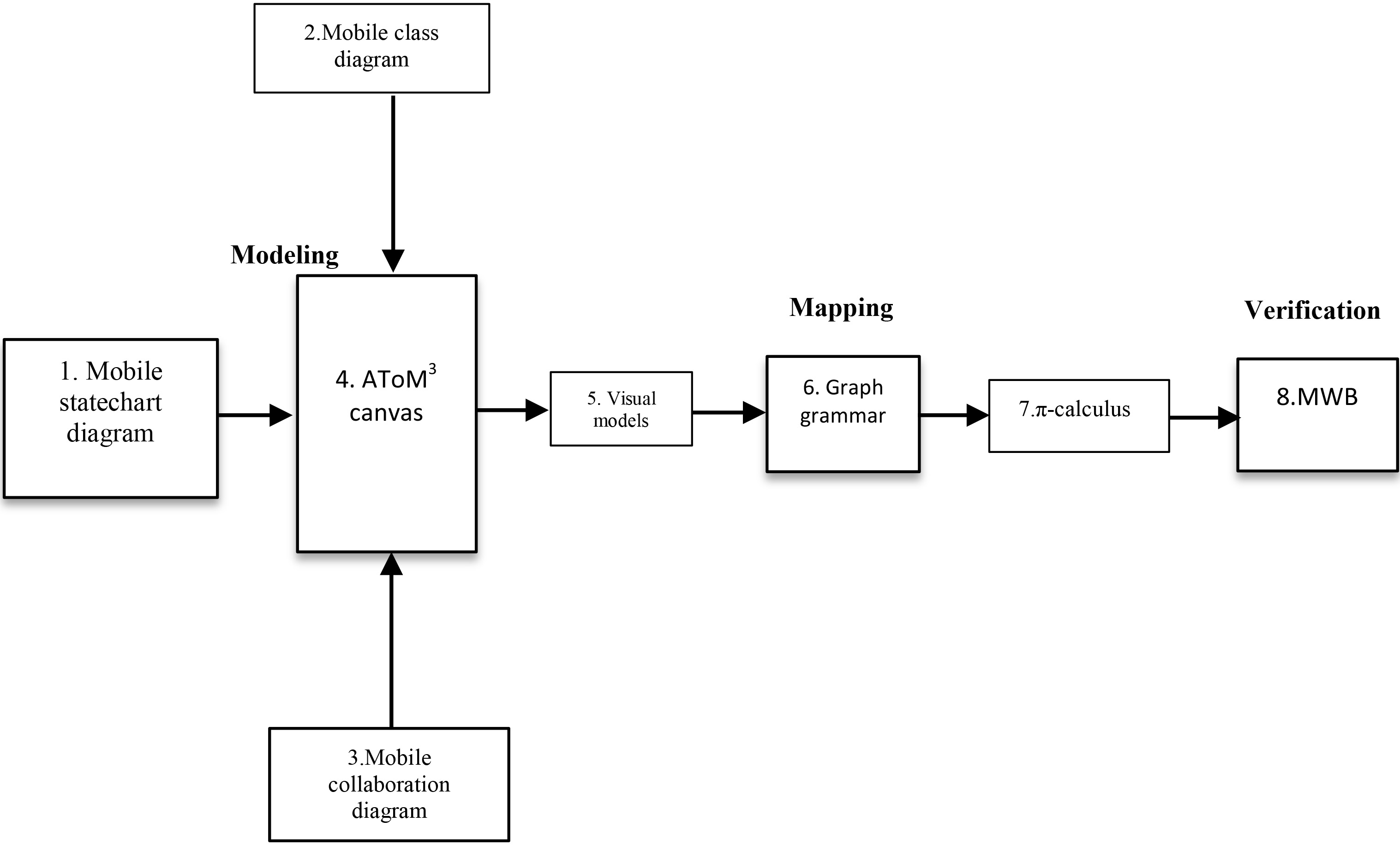
Modelling M-UML diagrams needs building an environment that allows their specification. Developing an environment from scratch is a very hard and costly task. Metamodelling was experimented as an effective solution. Thus, we formally specify them by means of meta-modelling. Each meta-model proposed has an abstract syntax and a concrete syntax which facilitate the description of these models. In the next lines, the implementation details of these metamodels which represent a part of the framework are described. The user of the framework (the analyst) should not understand such meta-models, but only specifies his system.
Mobile statechart diagram meta-model
Figure 3a illustrates the proposed meta-model of M-UML statechart diagrams named “EtatTransitionMobileMM” using AToM
Mobile statecharts.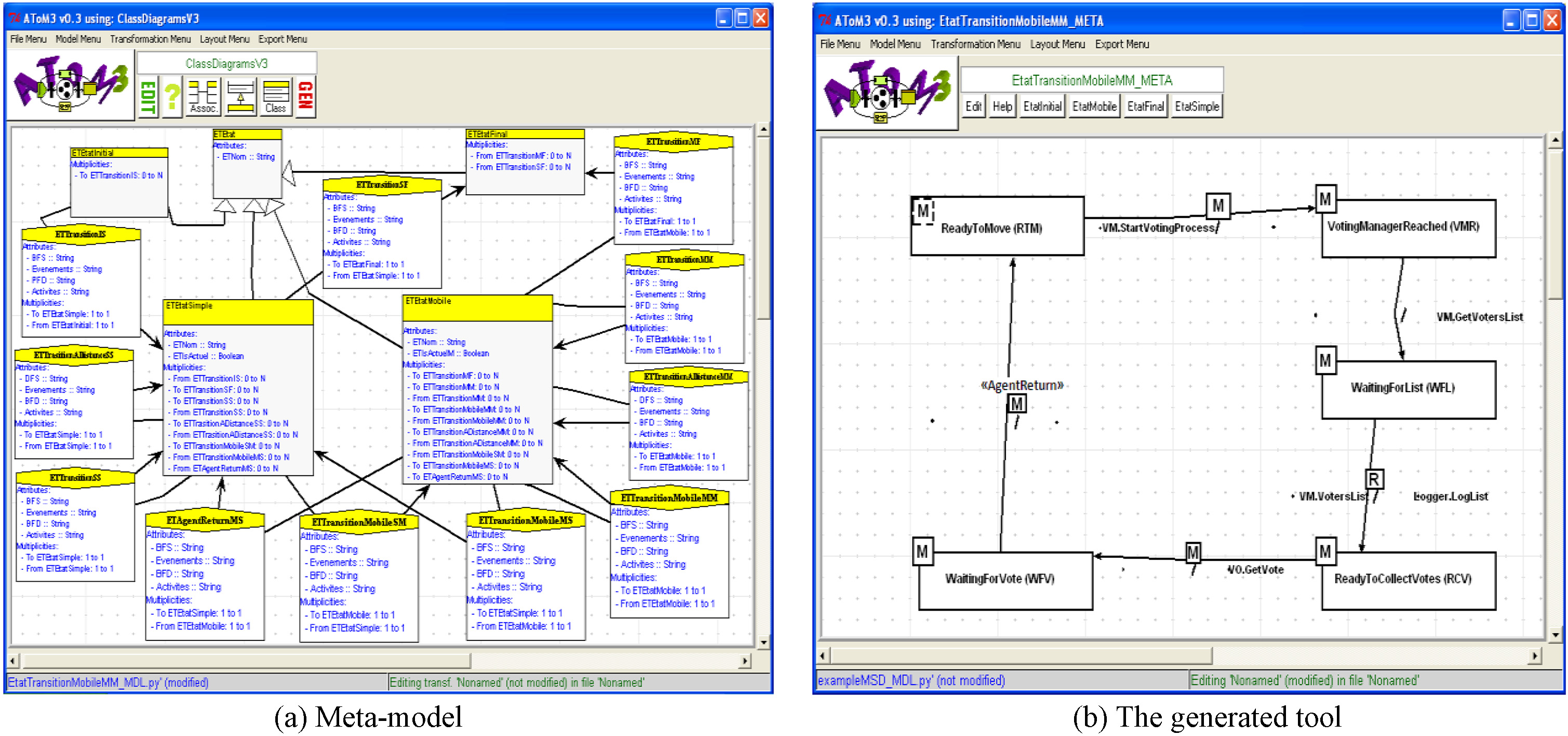
Figure 4a shows the meta-model “MobileClassDiagramMM” proposed for M-UML class diagrams using AToM
Mobile class diagrams.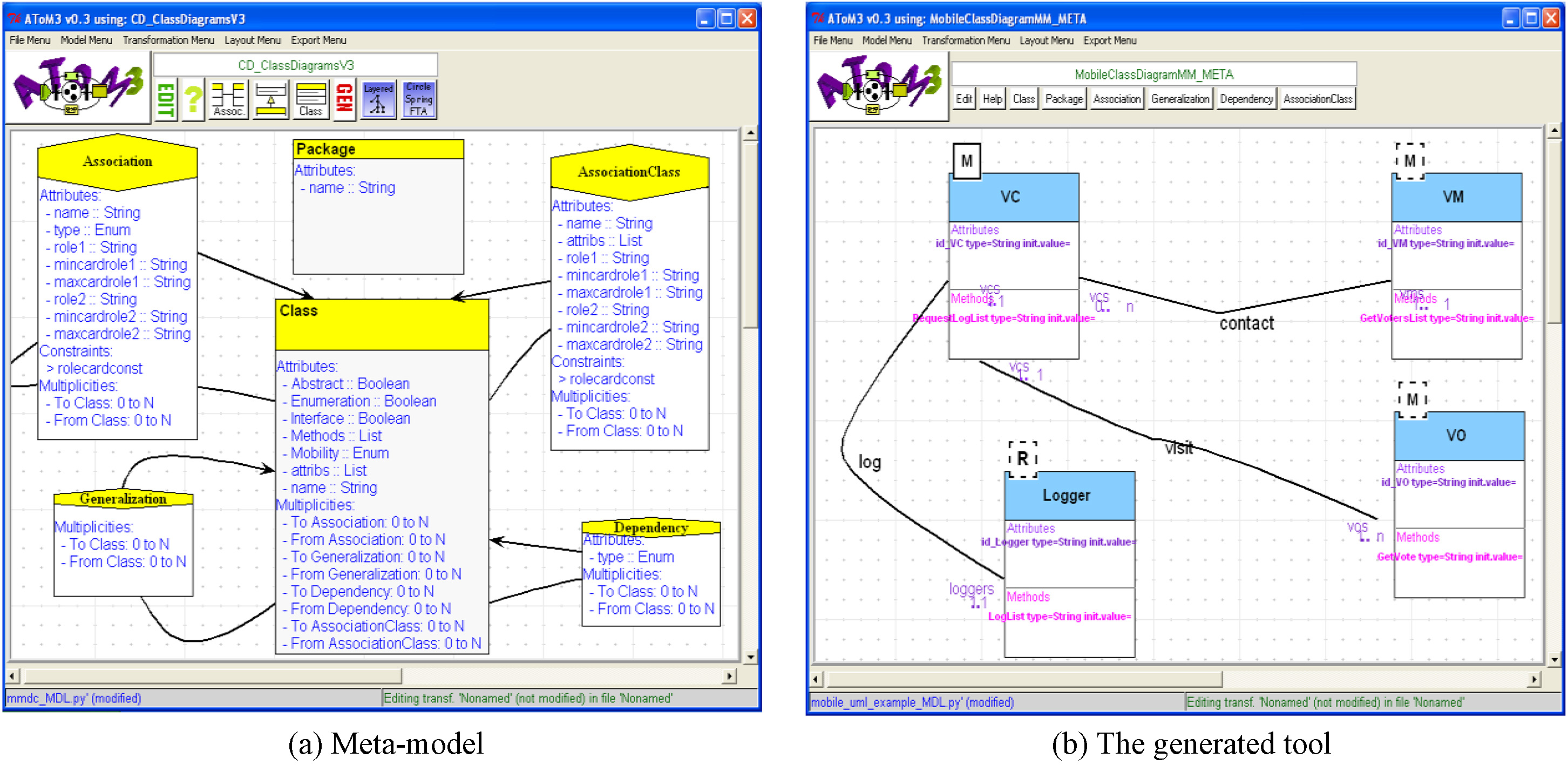
Figure 5a shows the meta-model “MobileCollaboration DiagramMM” proposed for M-UML collaboration diagrams using AToM
Mobile collaboration diagrams.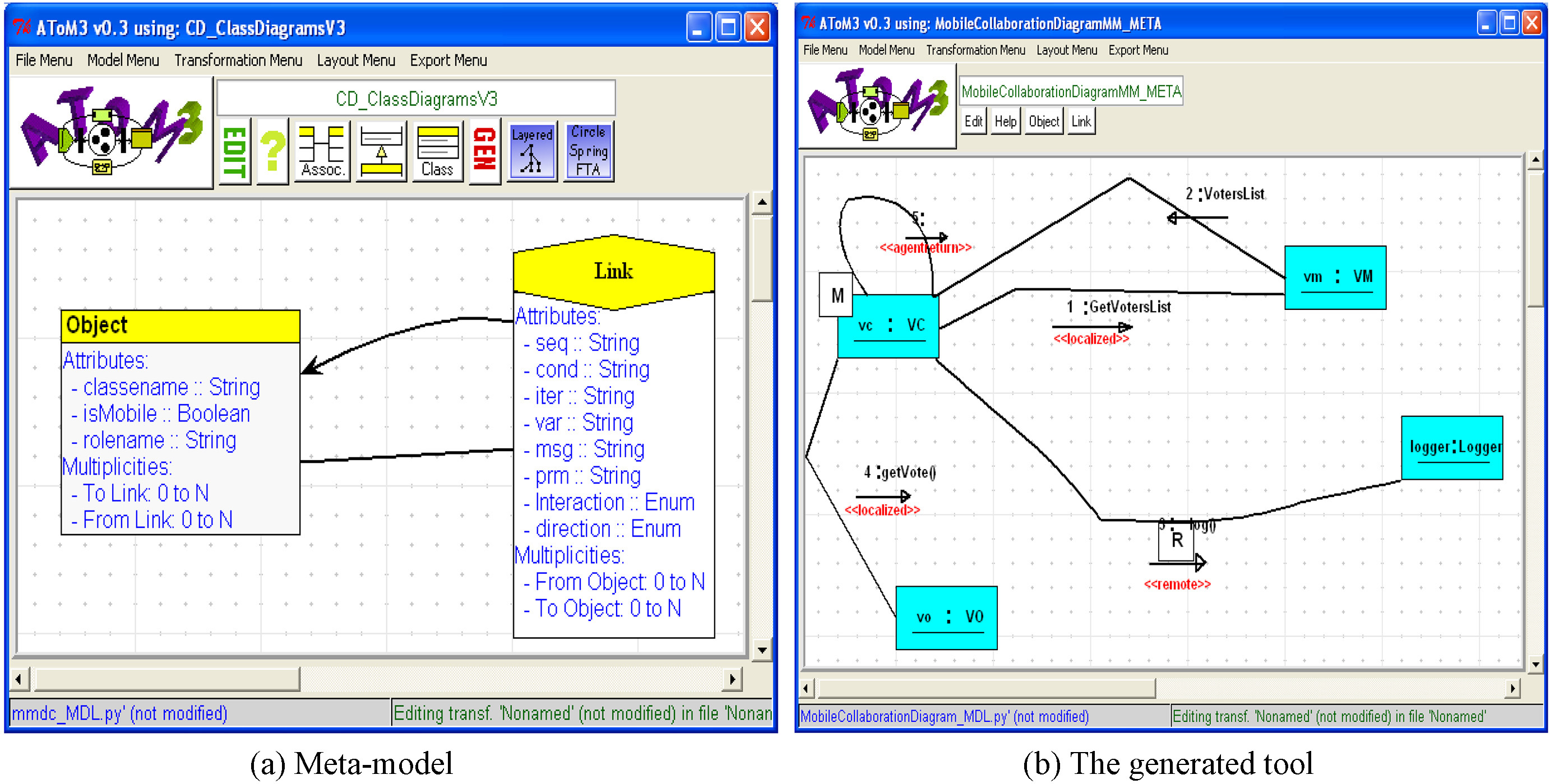
Semantics rules
Mobile statechart diagrams are already transformed into the
Table 2 recalls the mapping. In fact, the principle concept is that each agent in the diagram is represented by a parameterized process “Si()”, which represents its bahavior in its current state. This process will evolve to another process that represents its next state everytime the agent on the diagram changes its state to another one by performing a transition. Concerning the next state, it could be on the same platform as it could be at another one. The mobility of an agent is modeled by movement of links during the interaction between its corresponding process with a special process, used to represent the platform, named “Platform Scheduler (PS)”. This last is the responsible of enabling the movement of an agent (process) by authorizing it to reach or leave a platform. Each platform is recognized in this process by a channel “
Tansformation of mobile statechart diagram to
-calculus
Tansformation of mobile statechart diagram to
With regards to necessary additional information from other diagrams, several questions must be answered to obtain a full and coherent
Using the mobile class diagram and the mobile collaboration diagram, answers to the previous inquiries could be provided. In fact, each agent specified by this diagram belongs to a class in the mobile class diagram, this last gives more information about the behaviour of the agent in its methods in addition to its relationship with the other agents.
The mobile collaboration diagram allows composing the processes corresponding to different mobile statechart diagrams by assembling them in one process. This what covers the missing part in each mobile statechart diagram which supposed communicating with fictive processes during its formalisation. Therfore, this gives a complete vue of the interacting entities of the system. Events, also, are described in details in the mobile collaboration diagram (messages sending/receiving and their order). Actually, the mobile collaboration diagram identifies the events that a process Events Wrapper (ER) gets in each communicating statechart diagram. The order is related to the message number, using a FIFO strategy (first come first served).
Actions are described in details in the mobile class diagram as methods. Actually, A method tells us with details how the action will executed, for example if the action needs some arguments and if it returns something as results of the execution. So, the mobile class diagram gives details to the Action Handler (AH) how to execute the actions.
The proposed graph grammar is composed of twenty-six (26) rules used to implement the semantic rules above. In our case, the actions of the rules generate the corresponding
Figure 6 shows six essential rules which we have estimated that they are sufficient to well understand the automatic mapping. The other rules are very similar to the rules presented. When the graph grammar executes, the model is a blend of the three different diagrams, this is normal since what interest us is the rich
The proposed graph grammar.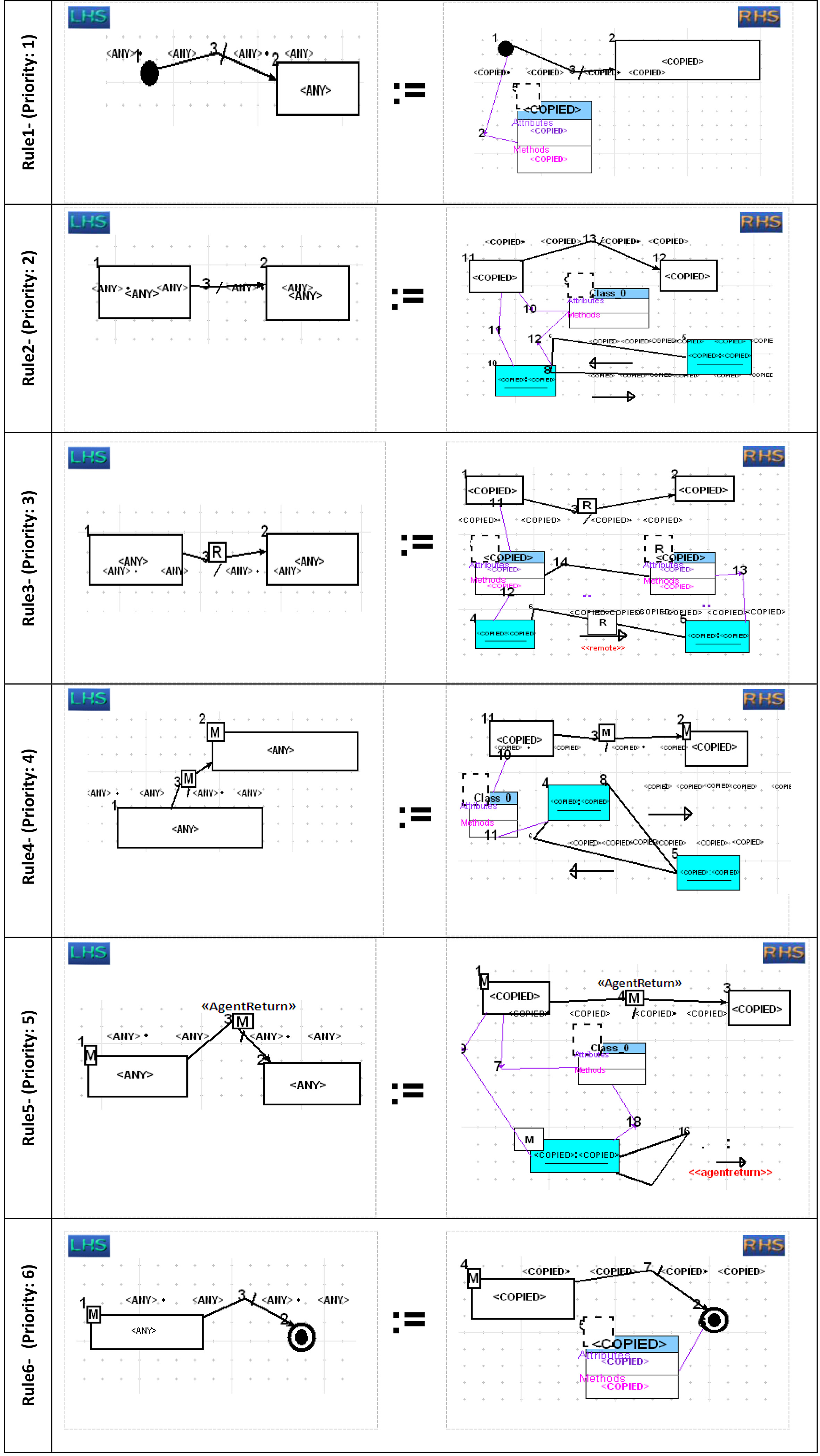
All the rules of the formalization have been implemented and the graph grammar will automatically encode in the
Details of Rule 4 with condition and action.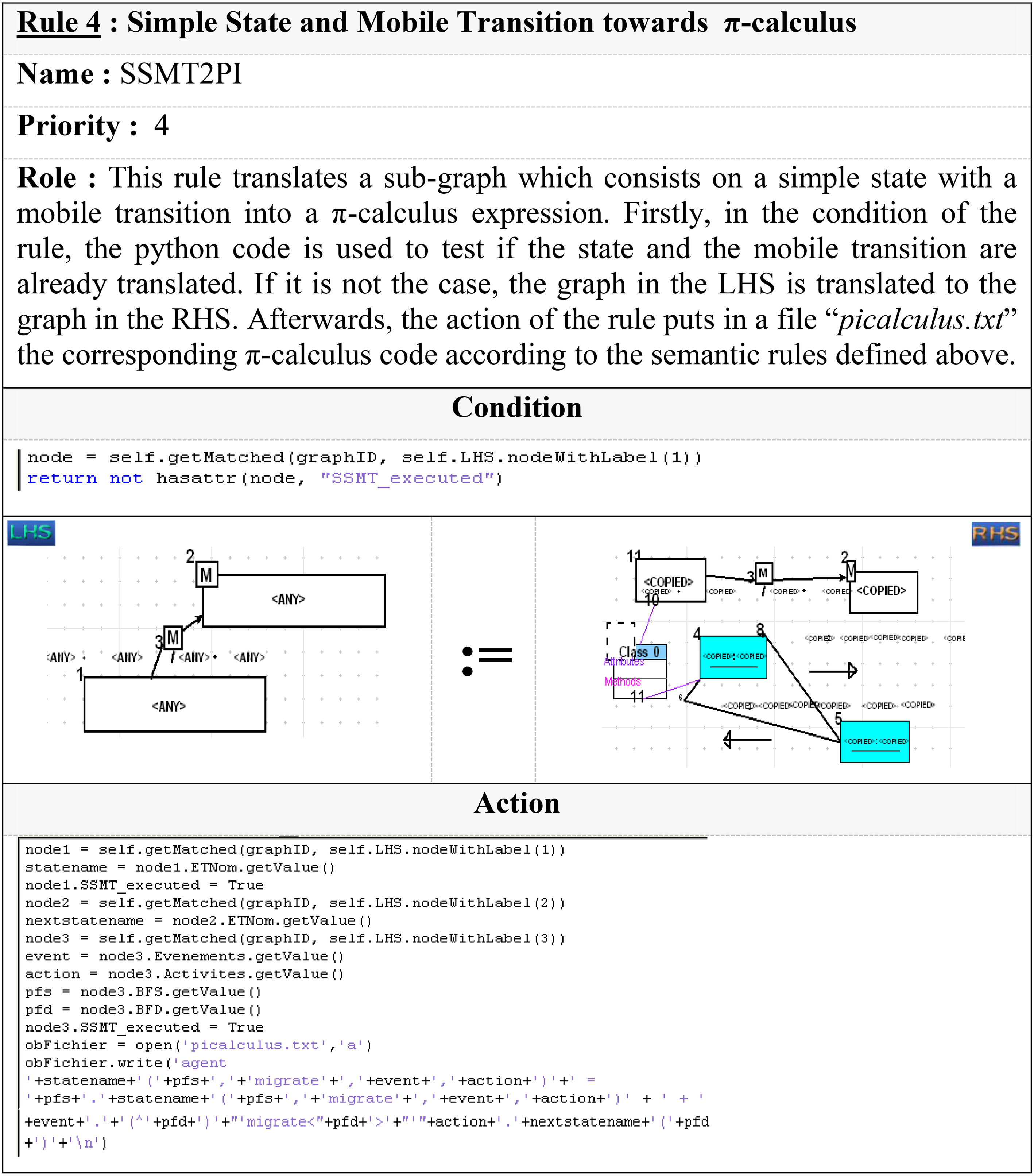
The previous rules show how the elements of the mobile state diagram bind to some elements of the others diagrams, i.e. class and collaboration diagrams, in order to retrieve necessary additional information. Moreover, the generation of the
Mobile Voting System (MVS)
As an example, a Mobile Voting System (MVS) specified in M-UML from [25] is taken. The system is composed of multiple type of agents: VC (vote collector), VM (vote manager), VOs (voters), Logger. Only VC is mobile, the others are stationary agents. In election time, the mobile agent VC gets a list of voters from a stationary agent VM (which mandates this VC), and visits the voters stations VO’s, which already have the list of candidates, in order to collect the votes results and forwards them to the VM that mandated the VC in question. The system can be expanded to have more agents of different types, but for reasons of simplification, four (04) agents are taken (one of each type).
Assuming that the designer has provided an M-UML specification composed of a mobile class diagram, a mobile statechart, and a mobile collaboration diagram. There is only one mobile statechart diagram that specifies the behaviour of the class VC of the mobile class diagram, the other classes do not have any associated statechart.
Figure 4b (or see Fig. 8 where all diagrams are gethered) shows the class diagram, it involves mobile and non-mobile classes. The class VC is used to instanciate mobile agents. The class VM is affected because it includes the method GetVotersList which is invoked by the class VC’s mobile agent. The instances of VM and VO are not mobile. The diagram shows the relations between VO, VC and the VM agents. The Logger class is associated with the VC class since it contains the method logList invoked remotely by a mobile agent of class VC.
Muli-paradigm modelling of the MVS in the developed tool.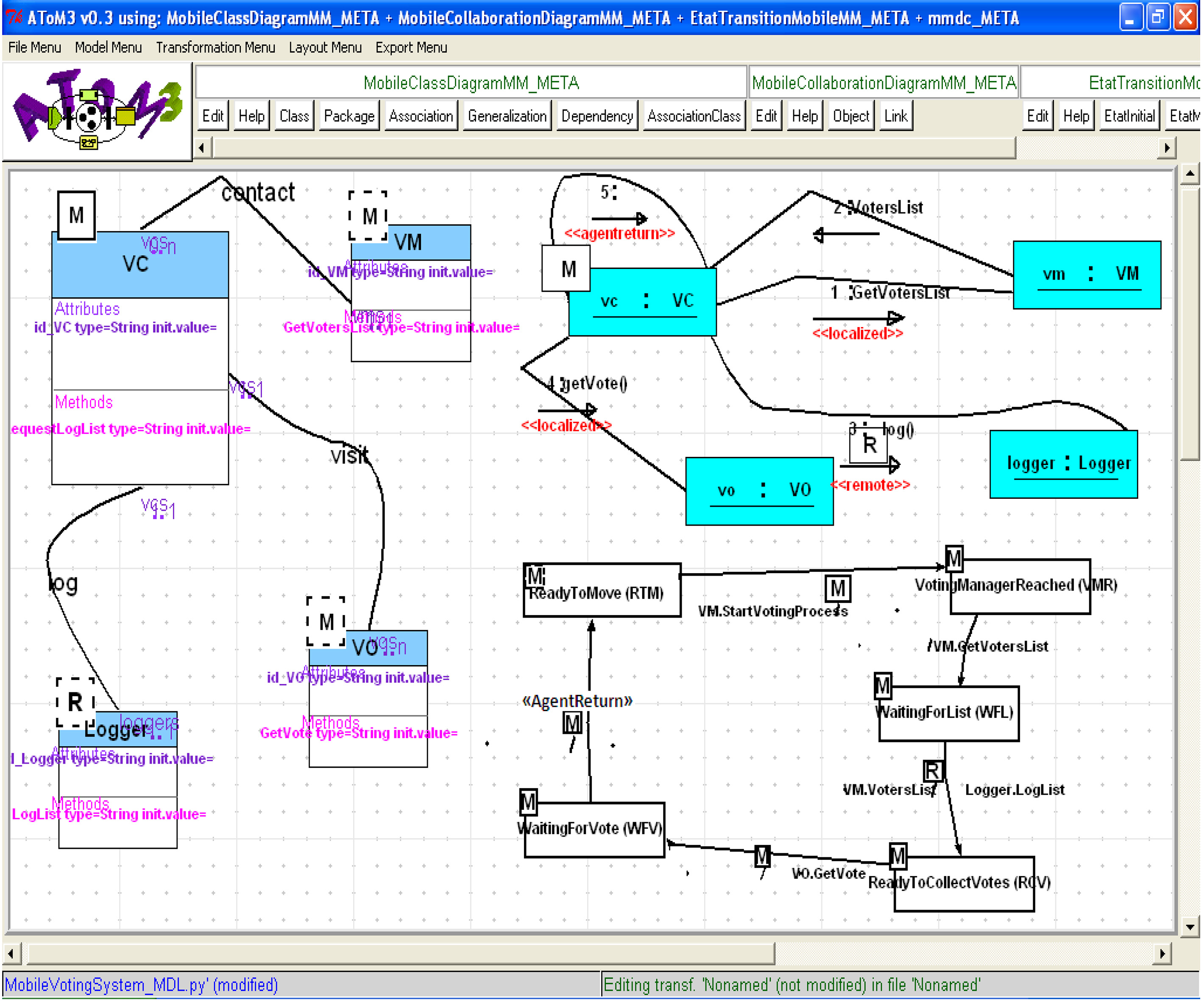
Figure 5b (or see Fig. 8 where all diagrams are gethered) illstrates an example of a collaboration diagram. The first and second interactions are localized interactions. The third interaction shows that VC (a mobile agent) is remotely interacting with the Logger agent at VM’s platform. The fourth interaction indicates the move of VC to VO’s platform to locally interact with a voter VO. The fifth interaction shows the return of the VC to its home platform.
Figure 3b (or see Fig. 8 where all diagrams are gethered) shows a state behaviour of the mobile agent VC. Initially, the VC is at its home platform in the state ReadyToMove (RTM) waiting to get an event StartVotingProcess. It then moves by a mobile transition to the state VotingManagerReached (VMR) located at another platform. At VMR, the mobile agent used to get the list of voters by performing an action GetVotersList and moves by a normal transition to the state WaitForList (WFL), where it waits for the list. At WFL, the mobile agent waits to receive an event VotersList, it then executes the LogList action while interacting remotely with the Logger agent and moves by a remote transition to the state ReadyToCollectVotes (RCV). At RCV, the mobile agent executes the action GetVote and moves by a mobile transition to the state WaitingForVote (WFV) at the first VO platform. At WFV, the mobile agent makes a
The full M-UML design of the Mobile Voting System MVS created in our tools is shown in Fig. 8, since the AToM
Thus, this M-UML design is translated into
The generated specification in Snippet 1 is presented with explanation, the MWB format is used which means that the restriction
Analysis
At this stage, a derived specification of
For example, one can verify standard properties such as deadlock and livelock of the agents VM, VO, VL, VC during their execution. Since there is one VM, one VO, one VL and one VC, their instanciation from their classes give VM1, VO1,VL1, VC1. The MWB shows that VM1, VO1, VL1 could deadlock, this is evident since their definitions contain states that have no out-going transitions due to the absence of their details of execution (expected to be modeled by statecharts, but unfortunately not provided by the designer). In contrast, the agent VC1 can not deadlock, the process PS and System also can not deadlock. The deadolock is checked in MWB by the command “deadlocks”.
Also, special properties, described by mu-calculus modal logic [12], could be verified, such as the following property on the PS process: for example, using the operator with the largest fixed point “max”, it can be shown that PS (the process which guarantee mobility of agents) will be always able to synchronize on an output port “p1” or on an input port “migrate”.
This safety property has two parts related by a disjonction: ([‘p1]TT & [i]W) expresses the fact that PS can always make an output on “p1”, and all the input actions that it is able to do will bring it to a state where W is true again. (
Verification using MWB.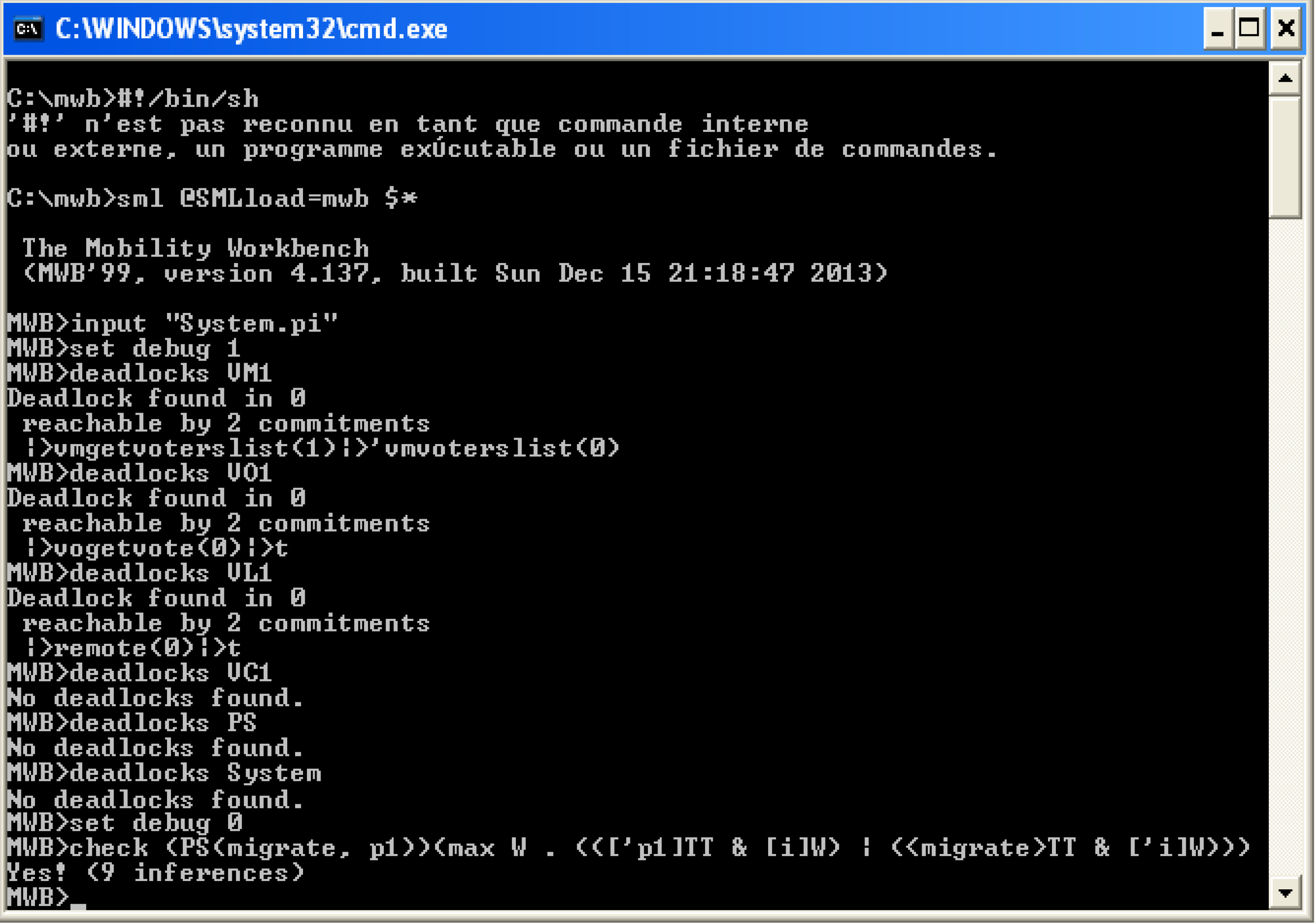
Figure 9 starts by importing the generated
This section provides some critical discussion points. The approach commonalities with the related work in the literature are especially the philosophy of combination of a graphical intuitive language to model a type of systems, and a formal rigorous method to verify them, such as in [9, 18, 19, 23, 28]. However, there are a lot of differences with regards to the work done.
The main contribution of this paper is the idea of using three views of M-UML at the same time, contrary to [2, 16], to enable full modelling of mobile agent based software systems (from different views to accumulate information), and transforming them together to
As cons of the approach, some users and although the UML simplicity, need some training in desining with that language, and the approach can’t garantee anything if first of all the user couldn’t provide correct conceptions. In fact, This is a common problem with all approaches which adopt UML, including the presented works in the literature. Also, we can evoke the problem of state explosion in model checking with MWB (in reality it’s not just with this tool), and this is what could hinders tackling modelling and verification of big complex systems. Another lack is that MWB doesn’t provide countre-examples when you got unverified properties, so it could be difficult for lambda users to understand and react to detected problems. In [9], we can not even talk about that because there is no support tool. Although that, since the MWB tool is based on “on-the-fly” approach, it gives more performance than other tools adopted in the related work (e.g. [11, 15, 17]), especially when big models (i.e. big systems) are manipulated, but nevertheless there is still work to be done.
Regarding applying our proposal on real world problems, it could be used in modelling and verification of a large range of mobile agent-based applications, since the general-purpose deliberately adopted during the development of the framework. Such real experimentations will be the subject of future work.
Finally, despite what we have already enumerated as limitations, we are sure that the approach makes a step forward in providing a real practical tool used by quite many users for specifying and developing such systems.
Conclusion
In this paper, a framework for modelling and verification of mobile agent based-software systems has been developed. A combined meta-modelling and graph grammar approach is adopted and the multi-paradigm tool AToM
Other diagrams of mobile UML (such as mobile activity diagrams) could be added to our framework, and this is what we are working on currently. Future work could includes developing an extended framework that contains more diagrams. By this way, we will guarantee that all views of the mobile agent system are covered. Another issue, we are currently working on, is hiding the verification process by extending MWB to simplify the verification task, such as returning a counter-example, so that a lambda-user can use easily our approach.
Footnotes
Author’s Bios