
Abstract
During the execution of a multi-agent system, a variety of events originating from the external environment and/or the internal elements of that system can lead to a state of failure. To overcome this kind of undesirable situations, the multi-agent system has to reorganize its behavior and structure in order to continue fulfilling its overall objectives. Several approaches are proposed in the literature that investigate the problem of reorganization at the design time. Unfortunately, we cannot detect all the events at design time, because several among them occur at run-time. In this paper, first, we propose an approach for reorganizing the multi-agent systems at run-time. Second, we propose to formulate the reorganization using graph transformation. In particular, we define a type graph to represent the multi-agent system organization and a set of rules that define the different actions that can be performed so that reorganizing the system. We evaluated our approach on a case study related to a Conference Management System which is implemented as a multi-agent system.
Introduction
Multi-Agent Systems (MAS) are often considered as a suitable paradigm for the development of complex systems [16]. They are applied in a variety of domains, such as social sciences, robotics, e-commerce, networks, virtual reality, artificial life, biological simulations, etc. [25]. Two types of multi-agent system design can be distinguished [18]:
Agent-centered multi-agent system (ACMAS): It relies on agents as the engine that generate and drive the organization. The design of the organization is not required beforehand. It is the implicit result of the collective emergence behavior of the pattern of cooperation between agents. It is bottom-up reasoning where the agents have to find out between themselves how to organize. For instance, the global behavior of the ant colony can be represented using this type of design where there is no organizational behavior constraints are explicitly defined within each ant. Organization-centered multi-agent systems (OCMAS): it tries to overcome the drawback of ACMAS (unpredictability, uncertainty [13]) by taking the opposite direction. Indeed, it is top-down reasoning in which the design of the organization is explicitly defined in advance. Thus, the cooperation pattern is established by a designer. In order to achieve the overall goal of the MAS, the behavior of an agent and its interaction with other agents has to comply with a set organization’s rules. In this type of design, the agents of the organization are aware of the structure and state of the system. This gives them the capability to manipulate primitives in order to alter their social environment.
Besides, the MAS is bound to the environment in which they operate. So, these systems have to deal with various predictable and unpredictable events, for instance when the MAS change its objectives or when agents leave the system for any given reason. If there is no reaction to these events, this can lead the system to a state of failure. By consequence, to deal with this kind of situations, the adaptation is a crucial ability has to be provided by the MAS in order to achieve its overall objective. The detection of such situations can be done at design time by the designer using different techniques such as model checking or simulation tools[18]. In this case, the designer has to perform the adaptation by changing statically the system’s model. Unfortunately, not all undesirable situations can be identified at this stage, but they can emerge at run-time.
In this paper, we propose a formal approach for adapting the MAS at run-time. In this way, we overcome most of the impracticable events, which keeps the system in a functional state. In fact, we are interested in the OCMAS type of MAS design. The adaptation in the OCMAS is called reorganization [18]. It is a process that could be endogenous or exogenous. The process of reorganization can be initiated by both an external entity or agents themselves, by reasoning on the different elements (e.g. goals, roles, and agent) of the MAS organization.
Our approach is based on a formal representation of the process of reorganization. We propose a way for creating such representation at run-time. To do so, we use Graph Grammar which is a formal language that is used to specify and verify a variety of complex and distributed systems [11]. In addition to this, we have used Graph Grammar because of the existence of tools support, such as AGG [20], GROOVE [19], etc. These tools offer different techniques for analysis purpose such as model checking, critical pair analysis, etc. In addition, Graph Grammar has a graphical nature that makes it intuitive and easy to understand.
The approach that we propose is composed of two main steps: i) We have defined a type graph that acts as a meta-model for representing the structure (state) of a given MAS. The system state is represented as an instance of such meta-model. ii) We have defined a set of rules representing possible actions that can be performed to reorganize the system. In order to evaluate our process, we implemented the type graph and the proposed set of rules using AGG. After that, we have used a concrete example with different scenarios so that testing all aspects of our approach.
The main contributions of this paper can be summarized as follow: Using graph grammar concepts to define a multi-agent system and describe the process of reorganization. To do so, we have: i) defined the type graph that represents the structural part of an organization. ii) defined a different set of rules to monitor and describe the behavior of a multi-agent system.
The remainder of this paper is organized as follows: Section 2 exposes multiple related works. Section 3 introduces an example that serves as a running example for illustrating our proposals throughout the paper. Section 4 gives first, an overview of the proposed approach. After that, we present the main concepts of graph grammar that are used in our approach, then we detail the proposed type graph and the set of rules that are used to describe the dynamics of the system. Before concluding and presenting the future directions of this work, we demonstrate our approach and discuss the obtained results in Section 5.
Multi-agent system (re)organization
MAS organization defines how to organize a collection of agents to form a MAS. Its center of interest is on the one hand toward the relationships and interactions between agents, and on the other hand, are the roles played by agents [22]. It consists of three components: organizational structure, an agent, and the environment [9]. In the field of OCMAS engineering, several methodologies and frameworks have been proposed for the development of multi-agent systems [12, 14, 6, 7, 13, 15]. In the latter, the key concepts used for the specification and the design of the organizational structure in these methodologies are agent, role, goal, and group. For example, the authors in [6] define a MAS organization as a set of agents enacting roles inside a structure with a view to fulfilling a set of goals. The set of roles, goals and the relation between them define the structure of the MAS organization. Where, every MAS organization has one or several Goals that justify its existence, and describe the purpose of its design [23]. Hence, a goal describes situations that are desirable, or the objective of a computational unit. In [21] the authors consider the Roles as similar to roles played by members of a particular organization structure. They are created and used to fulfill the organization’s Goals. Hence, a role defines a functional position inside an organization with a set of responsibilities to achieve a particular goal or a set of goals. The same authors define an Agent as an entity (human or artificial) that is conscious of its environment through sensors and act upon its environment to realize a set of assigned goals. It is characterized by their ability to be autonomous, reactive to the environment, pro-active and Interacts with other agents.
Besides, the MAS reorganization became a topic of interest in several research works. It is the answer to an alteration in the environment. Whether it is a local change at the agent level or a change in the overall purpose of the organization [9]. It enables the transition from one state to another more stable state. In [18] the process of reorganization is composed of two main phases: i) monitoring phase: its purpose is to detect any problematic change in components of the organization, whether it is a structural change or a behavioral change. ii) reparation phase: it performs at run-time the reorganization process in order to find back a stable state of the system as optimal as possible. This phase is performed only if a change is detected in the monitoring phase. Based on the nature of the change, there are two aspects of reorganization, namely, behavioral and structural aspects [9]: Behavioral change: it is a change that can occur at the agent’s behavior, and without modification in the organizational structure [9]. In the following cases, we can say that there is a behavioral change: 1) an agent enters in the organization. 2) an agent leaves the organization. 3) an agent enacts new role. 4) an agent changes its role. 5) an agent changes its capabilities. 6) an agent achieves its assigned role. 7) an agent fails to achieve its assigned role. Structural change: it is a change that can occur at the structural level of the organization. It implies a behavior change in the current and future set of agents. Based on the nature of the change and the involved structural components (role and goal), we identify the following cases: 1) new goal. 2) ended goal. 3) failed goal. 4) achieved goal. 5) new role. 6) ended role. 7) failed role. 8) achieved role.
Graph transformation approaches for MAS (re)organization
Some works have used graph transformation for the formalization of system reorganization such as [24, 1, 5]. In [24], the authors presented a model based on graph transformation to describe the process of reorganization in the context of organizational structures. They consider the following aspects of organizations: the social structure (roles and their inter-relations), the coordination relations between agents and the role enactment for agents. A meta-model of a multi-level graphs has been defined to represent the different aspects of organizations. This meta-model is divided into three levels i) Role-Graph level: it is composed of roles and their inter-relations, ii) Agent-Graph level: it consists of agents and their inter-relations iii) connection graph level: it consists of edges that represent role enactment for agents. It links the Role-Graph level with Agent-Graph level. In addition, the dynamics of the system (e.g. roles played by agents) are described by graph transformation rules of multi-level graphs. In our work, the proposed type graph can be considered as a meta-model for representing a MAS organization as a single graph. Unlike our work, the use of the meta-model in [24] needs to manipulate three graphs and the connection between them. We consider this, as an added complexity to the solution especially when we have a large sized organization with a high number of agents.
In [1] the authors have proposed a specification called Multi-Agent Graph Grammar (MAGG) for the representing MASs. MAGG is based on the Population-Organization Model (“PopOrg”) and Graph Grammars where two Graph Grammars are defined, i) Population Graph Grammars (PGGs) for representing the population level and ii) Organization Graph Grammars (OGGs) for representing the organization level. The PGG is defined as a set of agent graph grammars (AgGG) and the exchange capabilities of these agents. Each AgGG is defined by a graph grammar and a behavioral function. The grammar defines the type of agent being modeled, its initial state, and all its possible actions. In the OGG, the roles performed by agents are defined also as a set of role graph grammars. The proposed specification is not general but, it is specific to a single type of organization model which is “PopOrg” model.
In [5], a formal approach has been proposed to model and analyze self-adaptive systems. The system is modeled as a typed graph and its behavior is specified as a set of rules. The proposed graph grammar is used to model a specific system that is a “Car Logistic System”. Their solution cannot be easily applied in another kind of systems such as Multi-Agent systems. They need to redefine the proposed type graph and all the rules, which is not the case in our approach. We have defined a generic approach for any kind of Multi-Agent system organization. In fact, we have modeled most of the concepts (such as, Agent, Role, State, Goal,
Formal specification approaches for multi-agent systems
Several work have been proposed in the literature which aims to propose approaches and techniques to model and specify formally the multi-agent system such as [3, 8, 2, 17, 4]. The authors in [8] have tackled the problem of system reorganization by specifying formally the different actions that can be performed to do so. First, they used multi-modal logic to describe the organizations, organizational performance and the reorganization in multi-agent system. Second, this description is then used to define formerly the different action taken for the reorganization. Their work ensures that when an agent leaves the system, the organization still achieves its overall objectives. Another approach has been proposed in [17], which has as objective, specifying formally the elements of an organization (Agent, Group and Role). The authors proposed to transform organizational models given in “AgentUML” into Maude. In their approach, they simulate the system behavior which, allows to get feedback about the suitability of the solution. Besides, in [3], the authors proposed an algorithm to automate the generation of rewriting logic specification for multi-agent system models. A multi-agent system specified as a Petri net model is given as input to this algorithm. As result, a Maude specification is generated as output which is used later to verify different proprieties of the candidate system.
The Maude language and multi-modal logic that are used in these works to describe a MAS can be considered an added difficulty to the learning curve. They require that the designer must be familiar with these notations. On the contrary to these works, in our approach, we use graphs and graph transformation to formally describe a multi-agent system. We assume that graphs are intuitive and easy to use. They do not require any additional effort from the designer.
Running example
Before delving into the details of our approach, we introduce in this section an illustrative example that is used throughout the paper. This example is related to a manufacturing system producing different pieces. Initially, this system is composed of the following roles: a product manager (PM), an engineer (EN), and two supervisors (SP) to supervise the production of two types of pieces. For every piece, there is one machine, which is operated by a maximum number of two workers.
As any manufacturing system, this system obeys the law of demands and supply and it may change its goals. For instance, it can stop producing a particular piece and start producing a new kind of pieces. This change of goal will require a reorganization of the system in hand.
In the next section, we present our process that illustrates how to perform this reorganization at run-time. We will use our running example with different scenarios and configurations to show all aspects of our approach.
Proposed approach
This section covers the proposed solution for the reorganization problem in a multi-agent system using graph transformation. First, we give an overview of the proposed approach. Then, we present a set of definitions related to graph grammar concepts that are used in our approach. Third, we present in detail each step in our process.
Approach overview
Our approach consists of the formalization of the system organization and the process of the reorganization using the graph transformation. Before presenting the details of formalization, we describe in this section the MAS organization and the process of the reorganization as three main steps, where each step is implemented as a separate component as shown in Fig. 1.
Approach overview.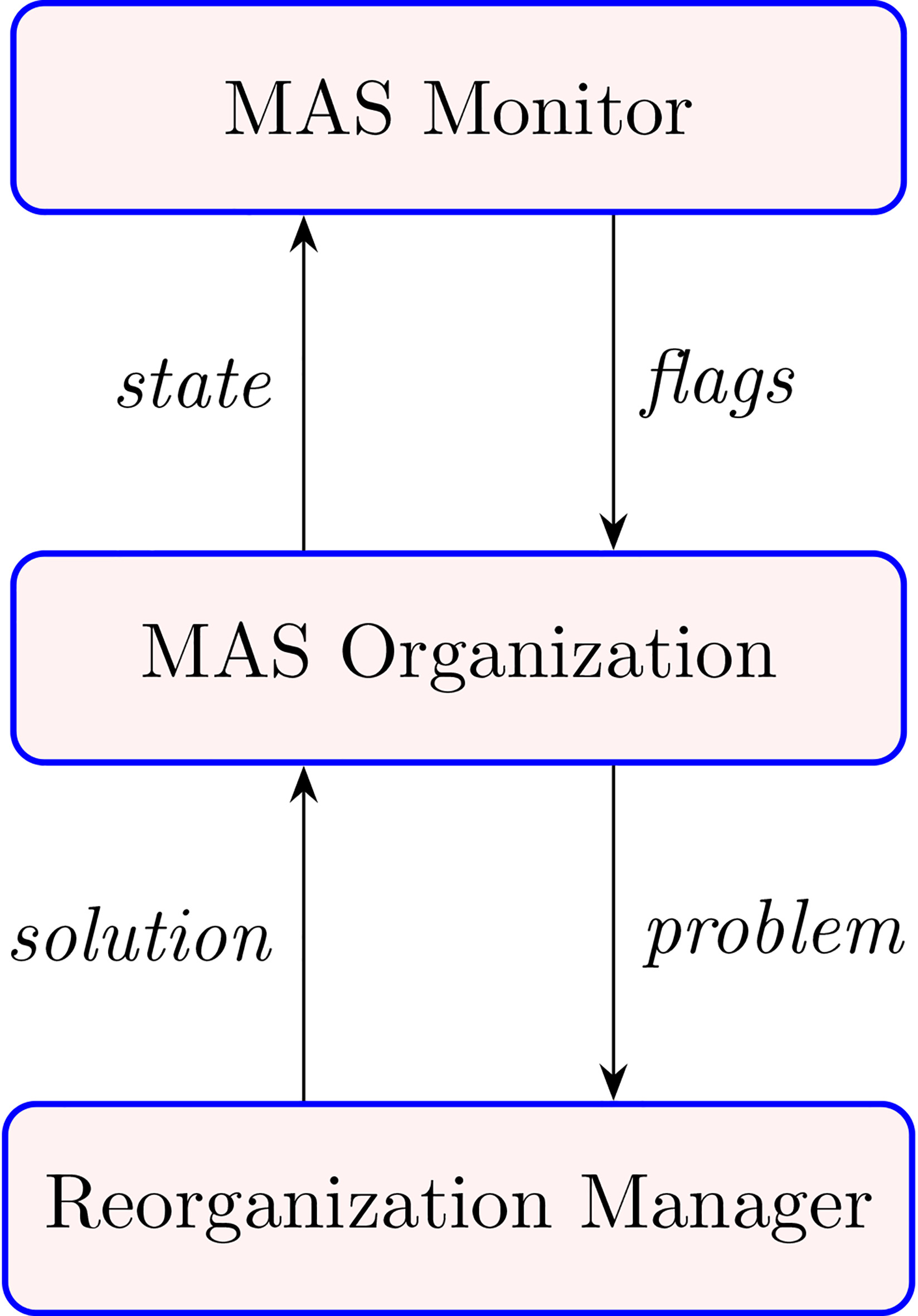
It monitors the system continuously in order to identify any undesirable change. Indeed, it provides a set of flags describing different kinds of changes that could occur in the system. It is defined as a set of rules. By applying these rules, the MAS Monitor component marks the system to trigger the reorganization.
MAS organization
It describes the state of a multi-agent system at a given time. In fact, the state of a MAS represents its condition which is identified by the set of flags provided by the MAS Monitor component. Therefore, we have two types of system states, which are: a normal state (a stable, and functional state) and a reorganizing state. For a system with a big number of goals, roles, and agents a reorganizing state may be composed of several reorganizing sub-state
Reorganization manager
It specifies how a multi-agent system is reorganized in response to a possible reorganization requirement. Hence, this component steps in the case of a reorganizing state. It is also defined as a set of rules, which once applied, they bring the system back to its normal state.
The application of different rules provided by MAS Monitor or Reorganization Manager components can modify the state of the basic elements (Goal, Role, and Agent) that are used to represent the MAS organization. The different changes that can be applied to these elements should follow a well-defined set of states transitions. All these transitions for a given element give what we call the element life cycle, which, starts from the existence of the element until its removal from the MAS organization. In the following, we detail the life cycle of each kind of elements.
Agent life cycle.
Agent life cycle: Figure 2 presents the life cycle of an Agent in the system. First, it starts with its entry into the system. Then, if it succeeds to enact a role, it goes to “Normal and Functional” state, else it goes to an “Idle” state. During its execution to fulfill the enacted role (when it is in “Normal” state), the agent may go to a state of failure. In this case, it can go to an “Idle” state, so it would be possible to replace it with another Agent. In addition, the designer1 can wait2 for the agent to come back to its “Normal” state and continue its Role. The waiting is not always a good solution, it depends on the nature of the system. For instance, in a critical system, the waiting could put the system in a devastating state. When the agent is in a “Normal” state and wants to change its new enacted role, so, it should go first to a “ChangeRole” state. After that, it returns to its “Normal” state, either accorded the wanted new role or not. When an agent is in an “Idle” state, two cases are possible, either, it waits for a new role to be enacted or it leaves the system. If the agent is in an “Achieve” state, it can only go to an “Idle” state. In some situations, an agent can choose to not continue its role, then, it can leave the system passing by the “Idle” state.
Role and goal life cycle.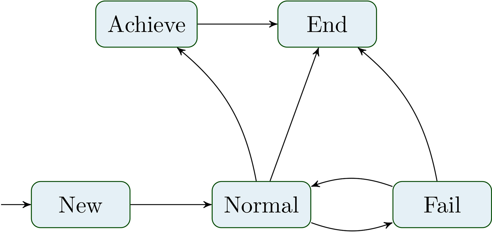
Role and goal life cycle: Figure 3 shows the life cycle of Goal and Role elements in a system. Each kind of elements starts with its creation. After that, it goes to a “Normal” state to be fulfilled. During the execution of the system, if the Goal (or Role) is achieved, the element passes to an “Achieve” state to go after that into an “End” state. If it is not achieved, it is put in a “Fail” state, where, we have two choices:
Waiting until resolving this failure and come back to the “Normal” state. Ending the goal, because, it cannot be recovered from this state or the waiting cost is expensive. For example, when a manufacturing system tries to produce new pieces, and this system has not (cannot acquire in the future) knowledge to perform this goal.
The main objective of our approach is the use of graph transformation to formalize the three components: MAS Monitor, MAS Organization, and Reorganization Manager. As we mentioned above, graph transformation is suitable to represent complex systems, where the dynamic part is modeled as a set of rules and the static part is modeled as a type graph. The MAS Organization component represents the static part of the system, which is formalized as a type graph. The MAS Monitor and Reorganization Manager components represent the dynamic part of the system. Hence, we formalize them as a set of rules that are called respectively: Monitor Rules, and Reorganization Rules. In the next sections, we give the detail of this formalization.
In this sub-section, we review the main concepts of graph grammar used in our approach according to the algebraic approach [10, 11]. In particular, we present graphs and typed graphs, which are used to model the static part of the MAS organization. After that, we present how to model the dynamic part of the MAS organization by using graph grammars.
Typed graph and typed graph morphism
We start this section by the definition of the basic notions of graph and graph morphism.
A graph morphism
These basic notions are extended by adding type information. Hence a type graph is a graph where nodes and edges are considered as a node and edge types, which can be used to assign a type to each element of a graph. A graph morphism between the graph and the type graph realize the typing itself.
Furthermore, an attributed graph is a graph where its nodes and edges may carry attributes. As for the standard typed graph, an attributed type graph defines a set of types which can be used to assign types to the nodes and edges of an attributed graph. An attributed graph morphism realizes the typing itself between the two graphs. The formal definition of attributed and typed attributed graphs is given in [10, 11].
The main idea of graph grammar is to describe the state of the system via typed graphs and to use graph transformation rules (called also: production) to define a possible change of states. Hence, a rule defines a possible action of the system. Following the double push-out approach (DPO), a rule is composed by three graphs,
The application of a rule (occurrence of an action in the system) means to find a match of
A Graph Grammar (GG) consists of a type graph, an initial graph, and a set of rules, where the formal definition is given by:
MAS organization type graph
We use the type graph to capture the structural aspect of the MAS organization. Figure 4 depicts the MAS organization type graph. This type graph contains a set of types which are used for modeling the MAS Organization elements, their states, and the triggering of the reorganization. Here, we detail each type in our type graph.
Type graph.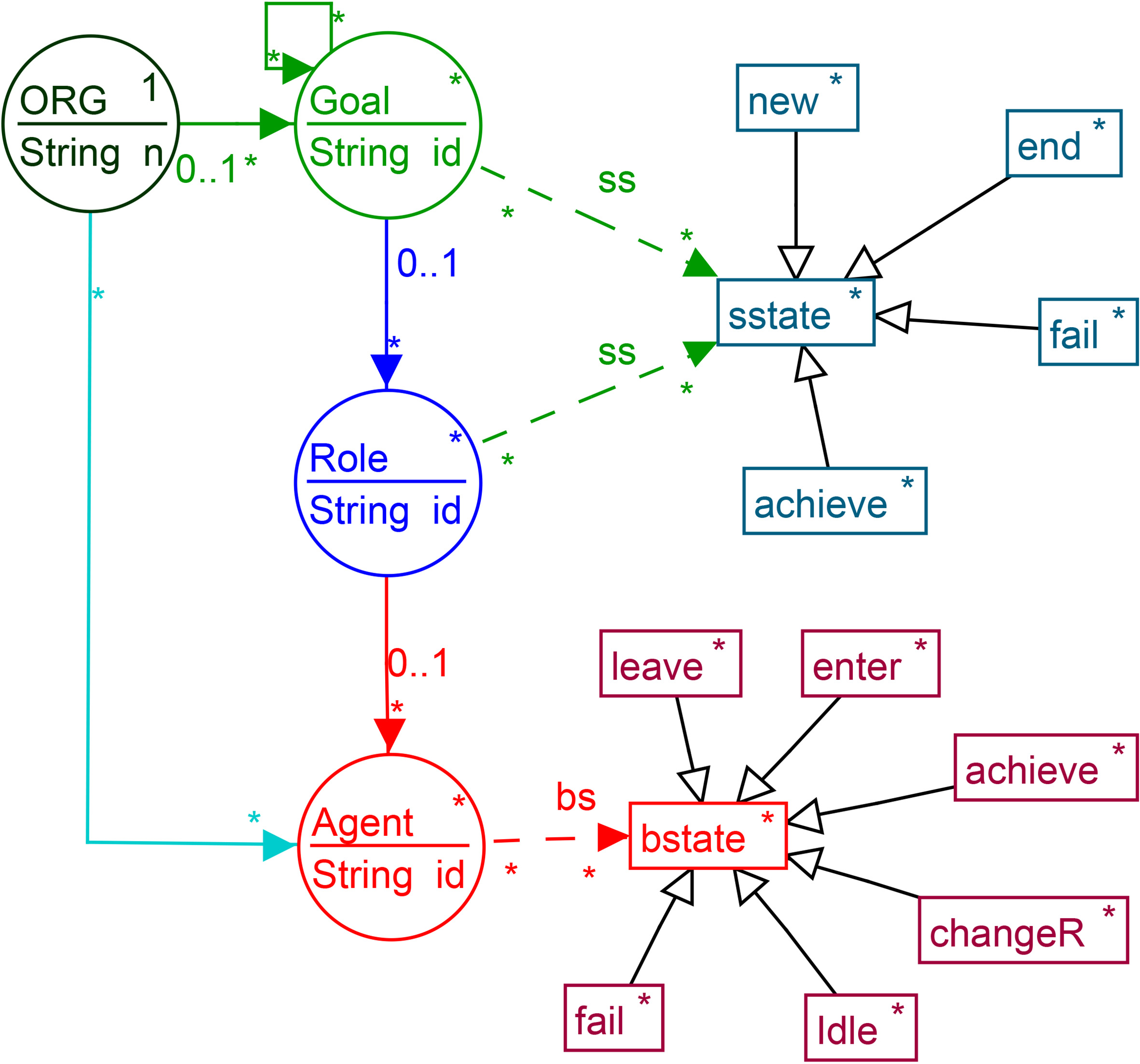
It is a unique and main element (root) in a type graph that represents a single MAS organization. All the other elements are attached directly or indirectly to this root. This element is an abstraction of the existence of a MAS Organization. The multiplicity of 1 to 1 is used to model the fact that this root element is unique. Each organization is characterized by a name that is modeled with an attribute called “n”. This node is an abstraction of an organization Goal (green circle in Fig. 4). Each goal has an attribute called “id”. This node has two incoming and two outgoing links:
A link that is coming from the ORG type. The goals that are connected directly to the ORG type represent the global goals. A reflexive link with “*” multiplicity: It means that each instance of a Goal can be linked to other instance of Goal. Therefore, a Goal can be solo or be composed of several other sub-Goals. This decomposition defines a hierarchy of levels of goals. In order to achieve a Goal, its children must be achieved first. A link goes to a Role node with a “*” multiplicity: it means that a Goal can have zero or multiple Roles. We note that parent Goals may have not Roles. A link goes to a sstate node, which represents the states that a goal can take. In our type graph, the control flow between Goals is expressed implicitly. This is because it represents only existing elements of an organization at run-time. Here we give some examples of such control flow. If we have two Goals It is an abstraction of an organization Role (the blue circle in Fig. 4). Each role has an attribute called “id”. This node has the following links:
A link to the Goal node. Each Role can be linked to only one Goal (multiplicity “0,1” in the type graph). A link to Agent node. Each Role node can be linked to zero or multiple Agents (multiplicity “*” in the type graph). The number of Agents connected to a Role determines the number of Agents involved (they collaborate together) to achieve this Role. A link to a sstate, which represents the states that a role can take. This node is an abstraction of an Agent (red circle in Fig. 4). like the other elements, an agent has an Id. It has the following links:
A link to a Role node by a multiplicity of “0,1”. This means that an Agent can be connected to zero or one role to fulfill the role functionality. A link to a bstate, which describes the states that an Agent can take. It allows to describe the state of the structural part of the system. It includes the following types: i) “new” to denote the creation of a new Role or Goal. ii) “end” to denote that a Goal or a Role has been ended. iii) “fail” to denote that a Goal or a Role has been failed. iv) “achieve” to denote that a Goal or a Role has been achieved. It allows to describe the state of the behavioral part of the system. It includes the following types: i) “leave” to denote an agent leaving the system. Therefore, to be removed of the organization. ii) “enter” to denote that an agent is entering the system. iii) “changeR” to denote that an agent wants to change its enacted role. iv) “achieve” to denote that an agent has achieved its enacted role. v) “fail” to denote that an agent has failed to achieve its role. vi) “Idle” to denote that an agent is in an “Idle” state.
It is important to note that, an element (Goal, Role, Agent) that is not connected to any of the sub-types of sstate and bstate, it is considered in a “Normal” state. Besides, our types (Goal, Role, and Agent) can be easily extended to provide further information or put a restriction on a certain operation. This extension takes the form of attributes. For instance, the type Agent may have the attribute “capabilities” to determine its skills. The type Role may have the attributes “min Agent”, “max Agent” to determine the maximum and the minimum number of agents that collaborate together in order to achieve this Role. Also, it can have the attribute “required skills” to determine the minimum skills that an agent must have to enact a Role.
As we aforementioned in Section 4.1, we model the dynamic part of the MAS organization as a set of graph transformation rules (Monitor Rules, and Reorganization Rules). In our approach, whenever a change in the system is detected or there is a need to reorganize, the corresponding rules are then executed at run-time. We present in this section, the main rules that can be applied to demonstrate the most pertinent states that can be taken by the system elements (Role, Goal, and Agent). The rule models an event that can occur at run-time (such as removing a goal from the system), or an act of a reorganization which is a response to an event. Formally in our graph, we represent this by marking the corresponding node with the corresponding flag to trigger the required response. For example, for removing a goal, we mark the node “Goal” by connecting it to a node “end” (of type sstate).
In the following, we illustrate what are the rules that can be involved in different kind of events. Applying these rules can change either the structure of the system or its behavior.
AgentEnter rule.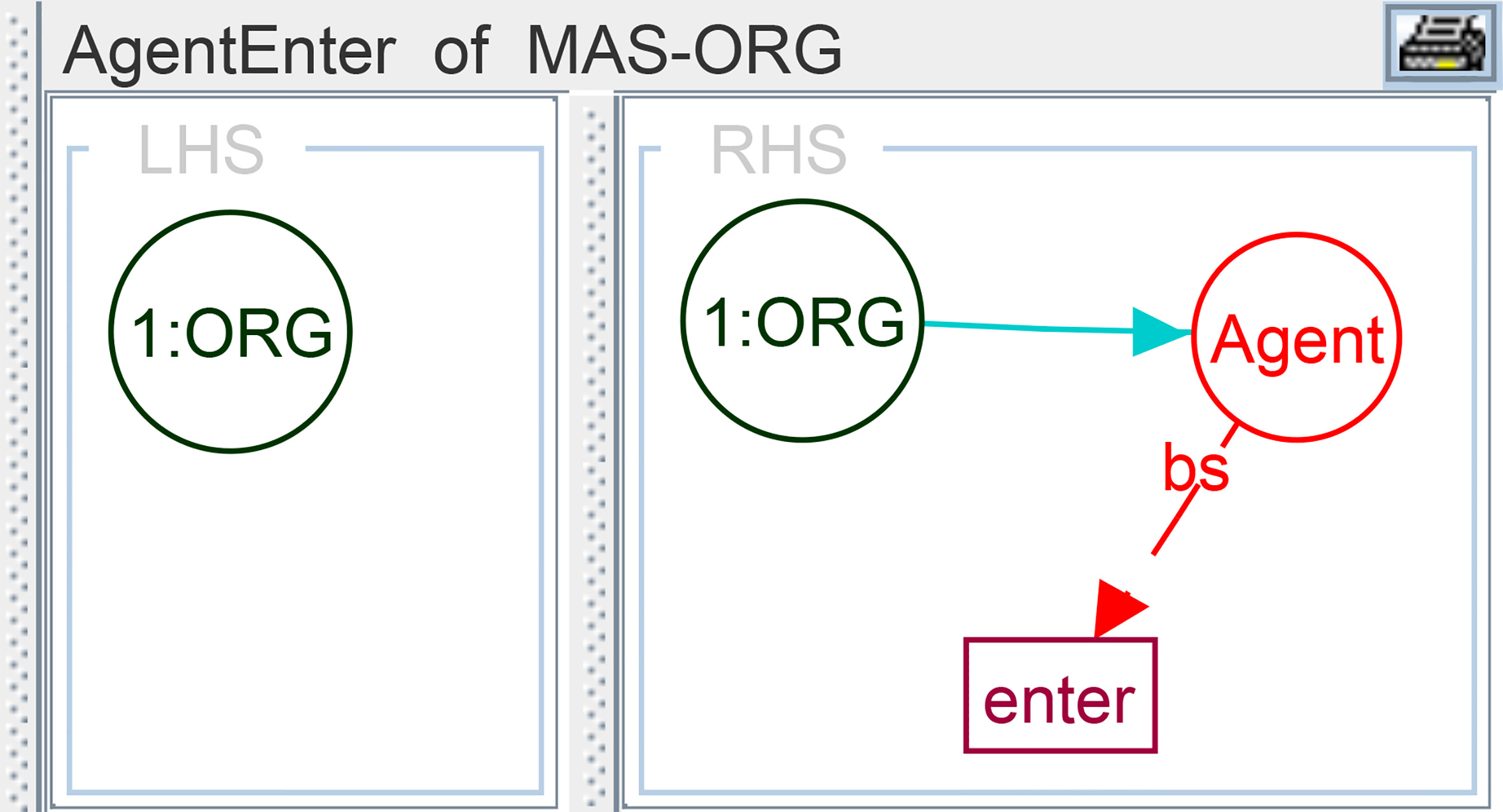
This event represents an agent that desire to enter the system. It is modeled by the rule AgentEnter as in Fig. 5. The application of this rule gives the new agent with a flag “enter” (see Fig. 5), which will trigger other rules to put it in an appropriate state according to the global state of the system (enact new role or put the Agent in an “Idle” state).
The designer can put an additional restriction on the agents entering the system to allow only those that have certain features or skills. For example, it is possible to restrict the set of agents to those that have some capabilities that allow them to operate a certain type of machines.
AgentEnactRole_enter rule.
This event represents an agent that desire enacting a Role in the System. So, this agent must be in an “Idle” or an “Enter” state. This event is represented by two rules, which are:
AgentEnactRole_enter Rule: In this rule, for each agent that has the flag “enter”, we create a link between the role and that agent. After that, we remove the flag “enter”, and the direct link to the organization node (see Fig. 6).
AgentEnactRole_idle Rule: In this rule, for each agent in an “Idle” state, we act as the previous rule, by deleting the flag “Idle”, and creating a link between the role and that agent (see Fig. 7).
AgentEnactRole_idle rule.
The policy of enactment of Roles is defined by the system designer. This designer can define a priority for the two previous rules. In addition, it can also define conditions based on the agent capabilities and the role requirements (for instance, what fittest agent cab play a given role?).
For each agent desires leaving the system (whatever his actual state “Normal”, “Fail”, or “Achieve”), it must be put in an “Idle” state. After that, it has the choice to leave the system or not. We present here the case of an agent in a “Normal” state and wants to leave. So, the rules that are involved are the following:
AgentSetIdle_normal rule.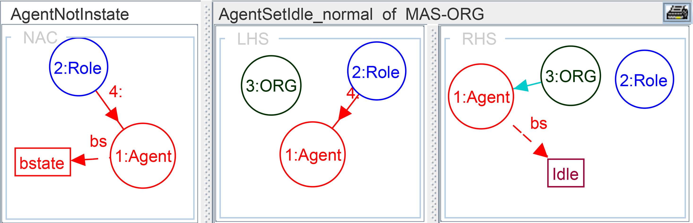
AgentSetIdle_Normal Rule: This rule (see Fig. 8) models the event of an agent that is already fulfilling a role and it is in a “Normal” state. For some reasons, this agent wants to stop playing this role. In this case, we put the agent in an “Idle” state by creating new node “Idle” and removing the link between the agent and the role, and creating a new link between the “ORG” node and the Agent. In addition, we create another link between the Agent and the new node “Idle”. The fact that the agent must be in a “Normal” state, this is modeled using a negative application condition (AgentNotInstate in Fig. 8).
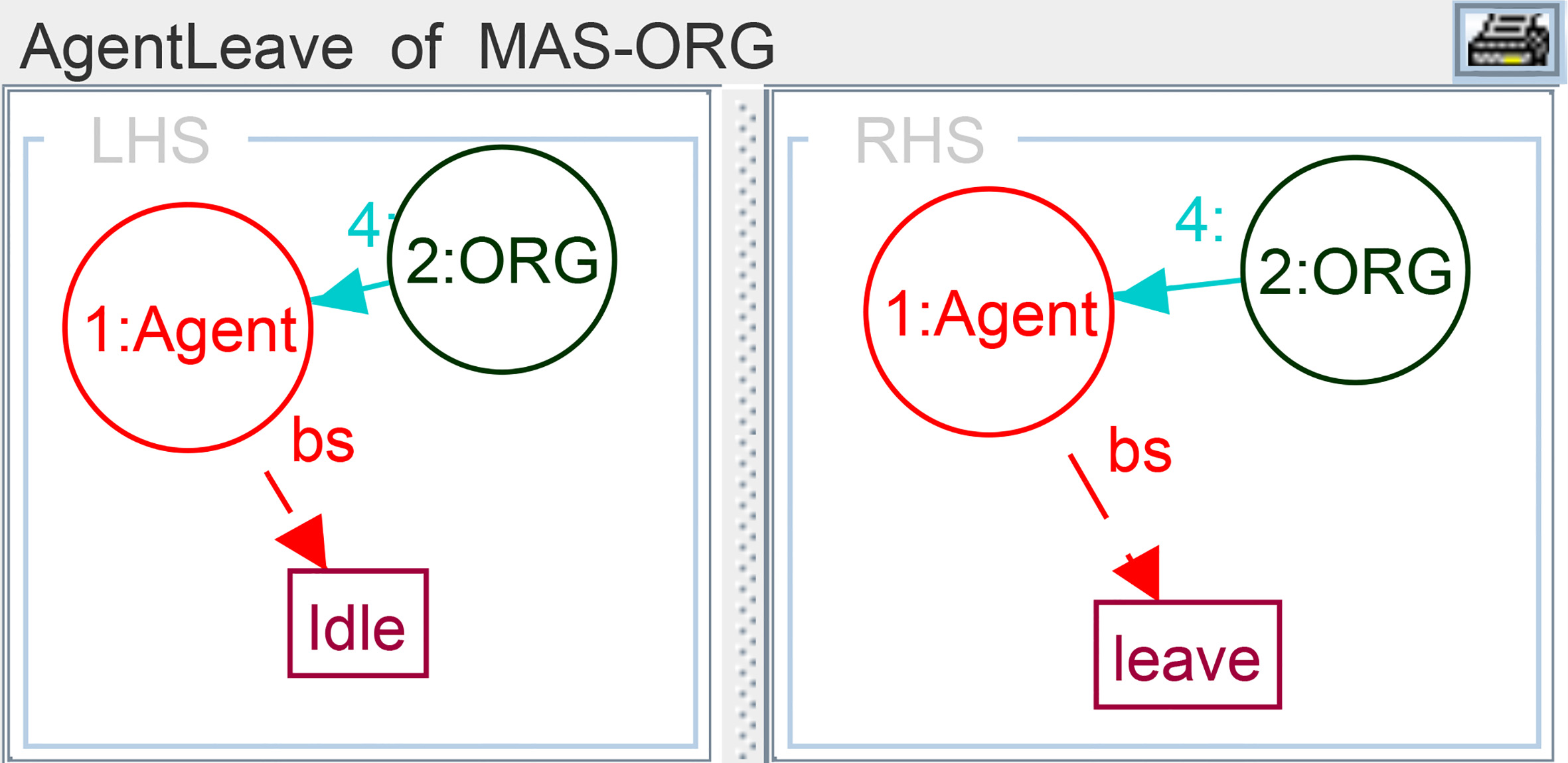
AgentLeave Rule: This rule models the event of an agent wants to leave the system. So, as in Fig. 9, we replace the “Idle” flag with “leave” flag.
AgentLeave rule.
AgentLeave_remove Rule: This rule models the leaving of an agent. In this case, we remove the node Agent and the flag “leave” (see Fig. 10).
AgentLeave_remove rule.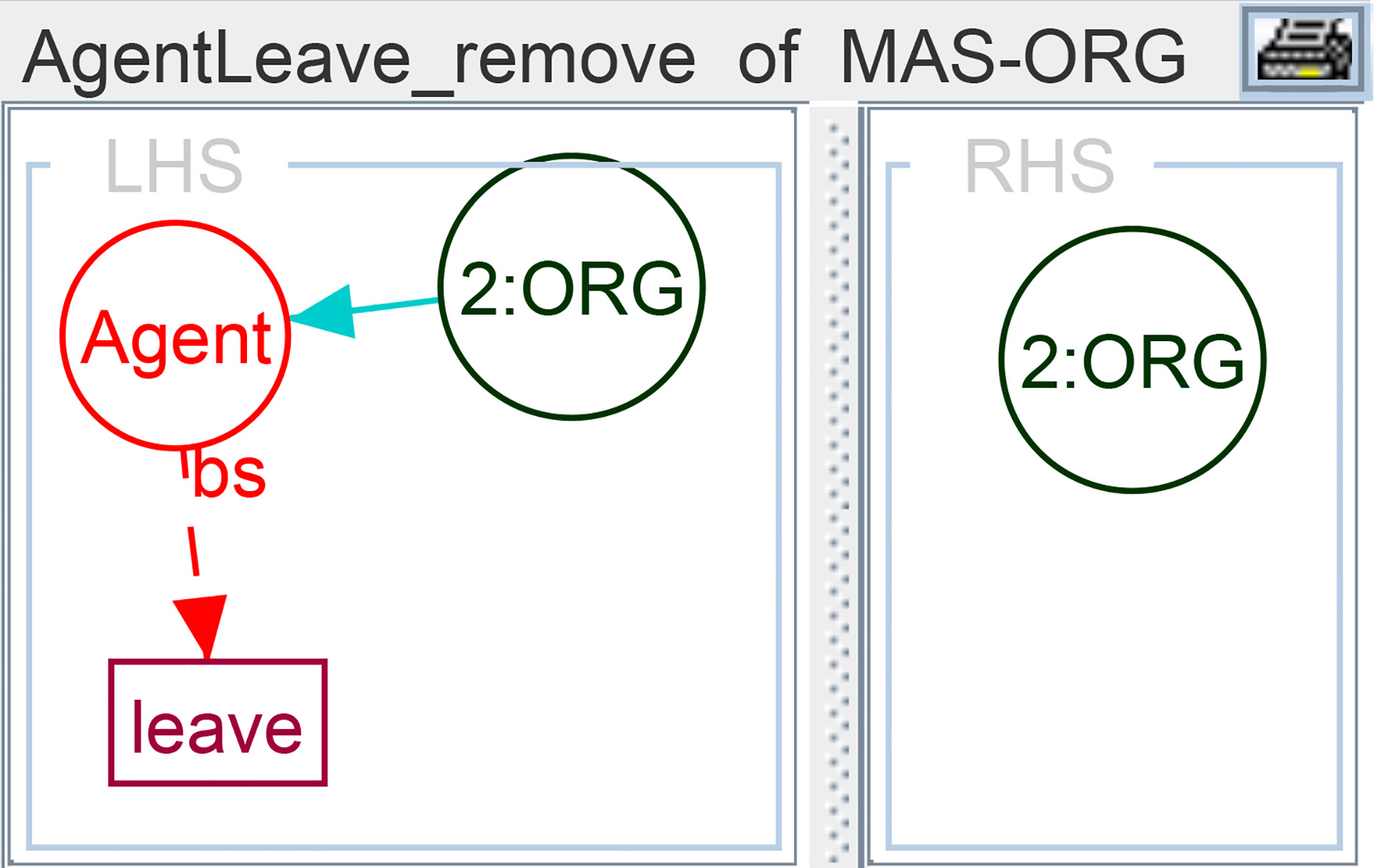
A Goal can be ended for many reasons, which are related to the overall objective of the system. For example, ending the Goal of producing a piece, because there is no longer in demand. For this, we have the following set of rules:
GoalSetEnd rule.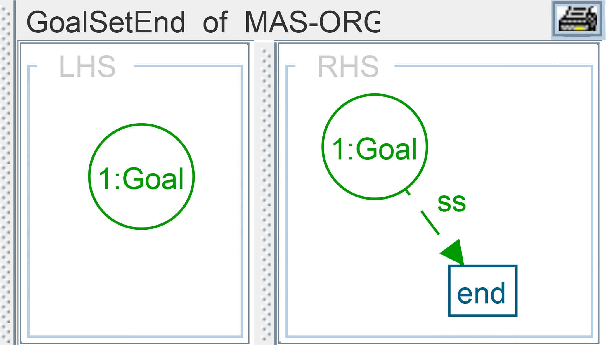
GoalSetEnd Rule: In this rule, as shown in Figure 11, we mark the Goal to be removed from the system with the flag “end”. As a response to this event, other rules should be applied to reorganize the system. We resume these rules as follows:
mark all Goals in its hierarchy with the flag “end”. mark all Roles that are attached to the ended goals by the flag “end”. put all Agents that are attached to the ended roles in an “Idle” state. remove from the system all Goals and Roles that have the flag “end”.
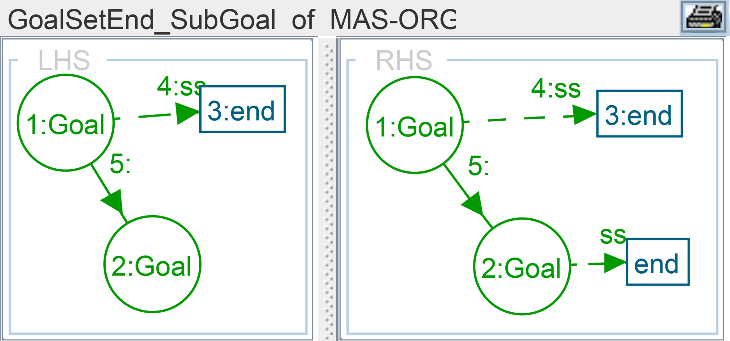
GoalSetEnd_SubGoal Rule: This rule is applied for each sub-goals. It enables to mark them by the “end” flag (see Fig. 12).
GoalSetEnd_SubGoal rule.
GoalSetEnd_Role Rule: This rule enables to mark a Role attached to an ended Goal by the flag “end” (Fig. 13). In some situations, the Role can be ended without ending the Goal, but for a reason such as a Role is achieved. In this case, we apply other rules.
GoalSetEnd_role rule.
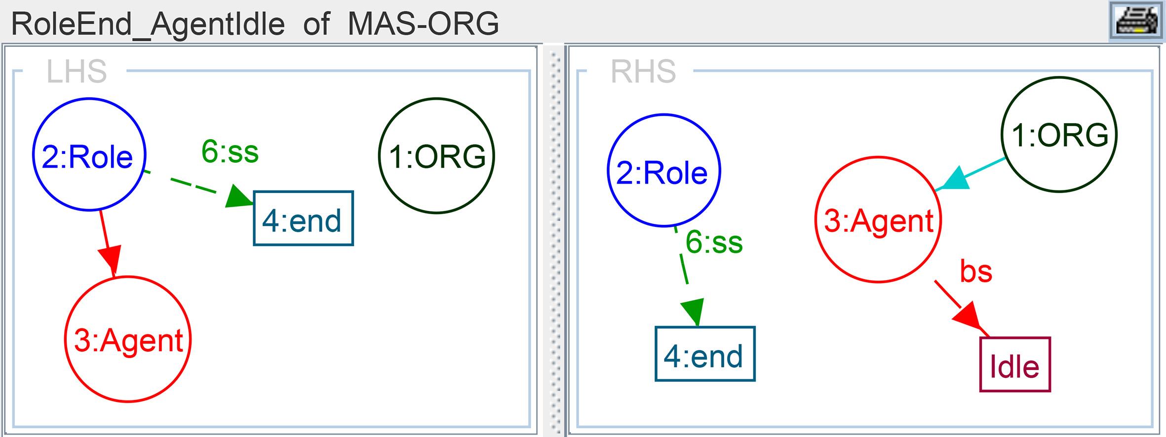
RoleEnd_AgentIdle Rule: This rule is applied in response to an ended Role event. It puts the agent in an “Idle” state when the Role is ended (see Fig. 14).
RoleEnd_AgentIdle rule.
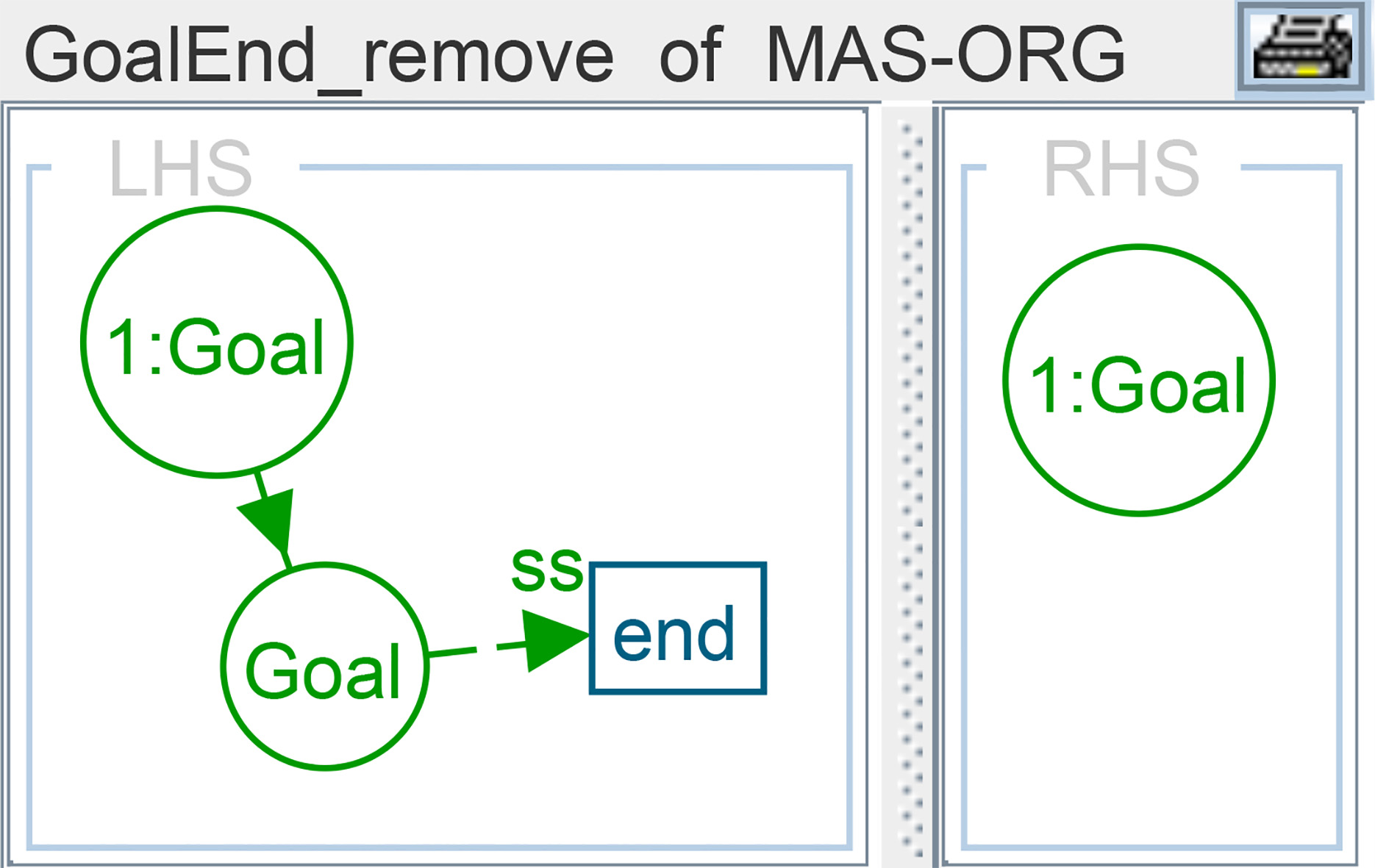
GoalEnd_Remove Rule: This rule removes from the system all the Goals that are marked by the flag “end” (Fig. 15). For Goals that are attached directly to the organization (the ended Goal is attached to the ORG node in the left-hand side), we apply another rule. Indeed, on the right-hand side, we maintain only the ORG node.
GoalEnd_remove rule.
RoleEnd_Remove Rule: In this rule, each Role that is marked by the “end” flag is removed from the system,

To achieve a goal, we start applying changes on the leaves in the hierarchy of nodes that are connected to the node that represents this goal. These as changes are described as follow:
we mark the agent with a flag “Achieve”, when it finishes its enacted Role. In this case, we put this agent in an “Idle” state. in the same way, we mark also the Role with a flag “Achieve” when its connected Agents have this mark or the designer decided that this Role has been achieved. In the second case, the agents connected to this Role are put in an “Idle” state. we mark the Goal with the flag “achieve” when all its connected Roles and Sub-goals are achieved. we mark the achieved Goal with the flag “end” in order to remove it from the system.
All these changes are formally defined as rules. For the readability reason, we give only one rule (called RoleAchieve_AgentIdle Rule) that is related to the second change. This rule is illustrated in Fig. 16, which represents a response to an achieved Role.
RoleAchieve_AgentIdle rule.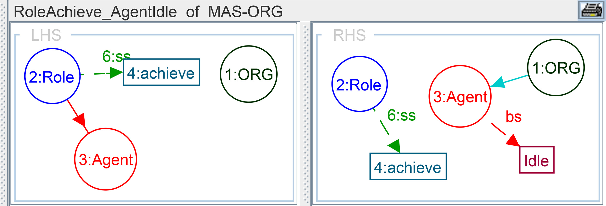
Depending on the nature of the system, we distinguish two types of failures: recoverable, and unrecoverable failure.
GoalFail_recover rule.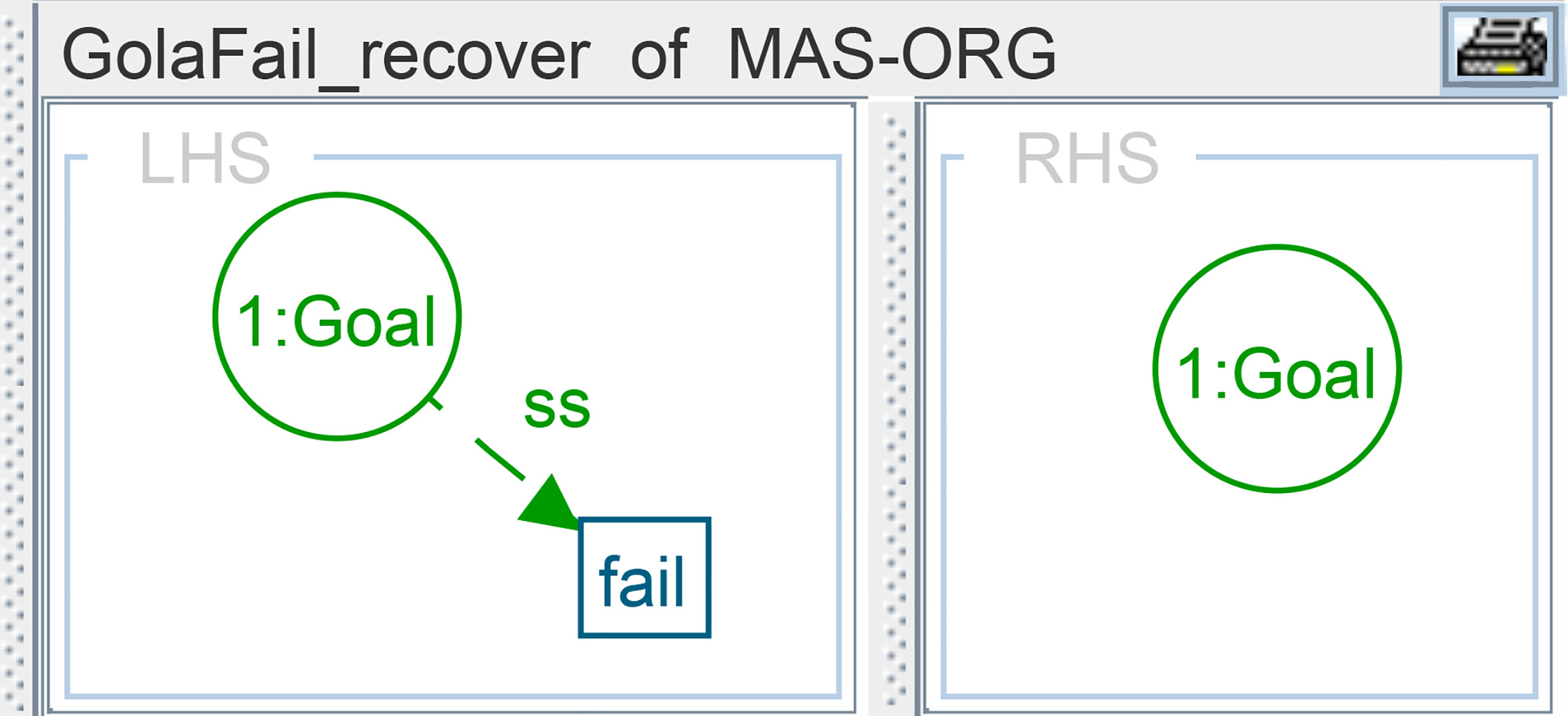
Initial graph of the running example.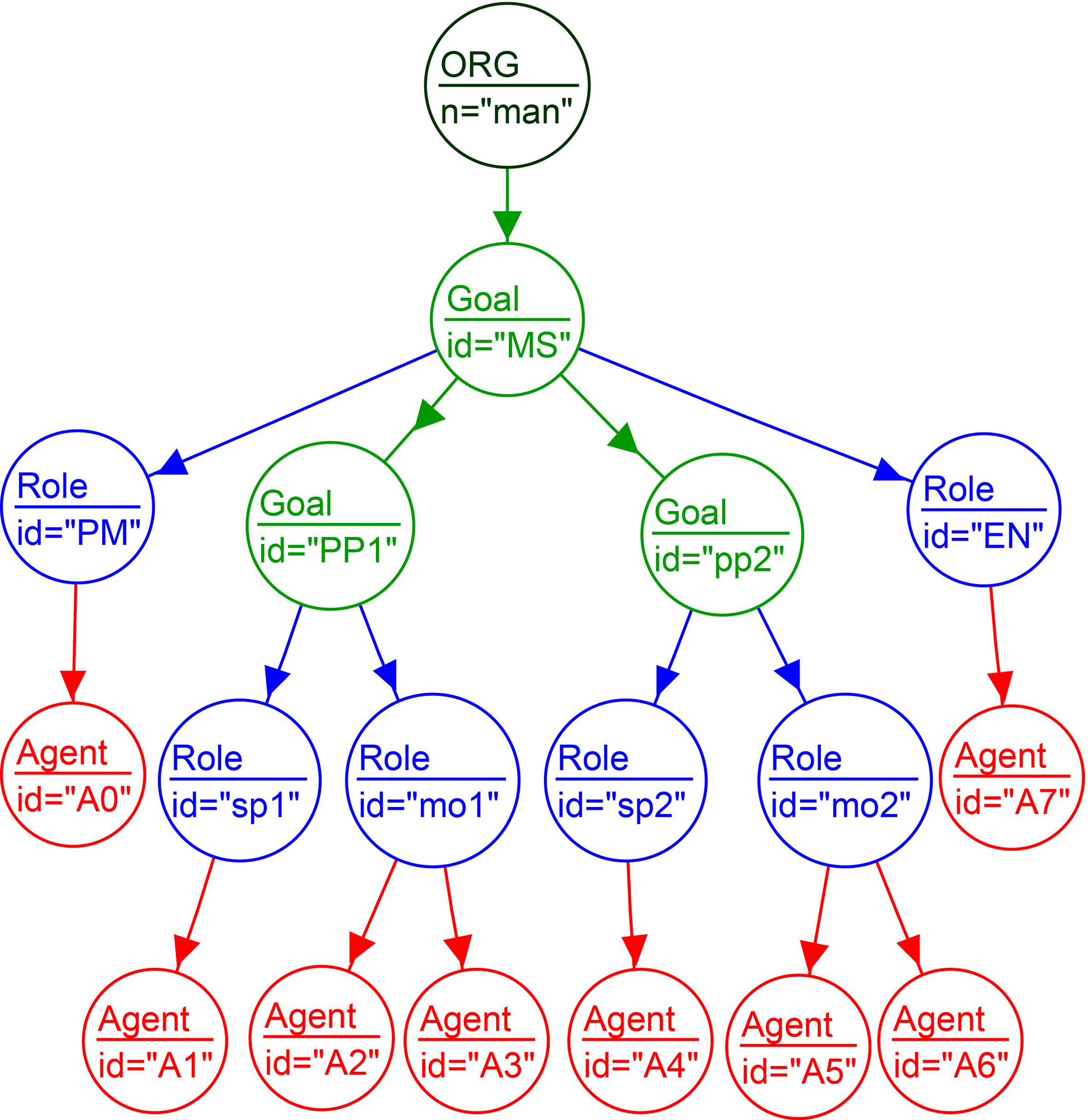
The recoverable failure is represented in the life cycle of a goal as a connection from the “Fail” state to “Normal” state. The rule that is applied here, removes the flag “Fail” from the Goal node (see Fig. 17). In the unrecoverable failure, the “Fail” state is connected to the “End” state. Here, the rule puts the Goal node in the “end” state.
In order to evaluate our approach, we have used in this section the previous running example as a case study. The graph that model the initial state of our running example is shown in Fig. 18. In this initial state, we have one global Goal related to “Produce Pieces Goal” (PPG). This goal is decomposed to two sub-goals: “Produce Piece 1” and “Produce Piece 2”. They are labeled respectively PP1 and PP2. For each sub-goal, there are two Roles attached to it. For example, the sub-goal PP1 has attached to the roles “supervise product 1” (labeled as sp1) and “machine operator 1” (labeled as mo1).
Scenario of agent entering the system.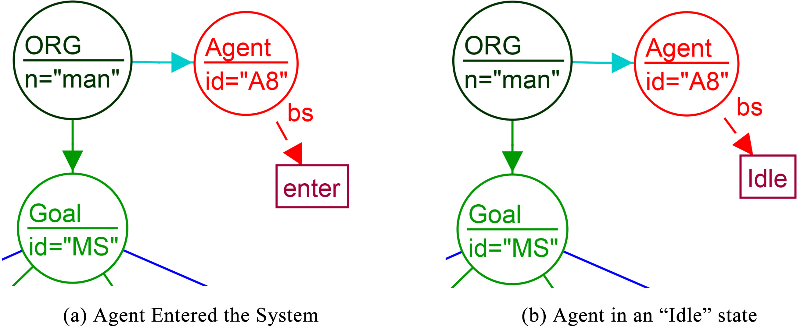
Scenario of agent leaving the system.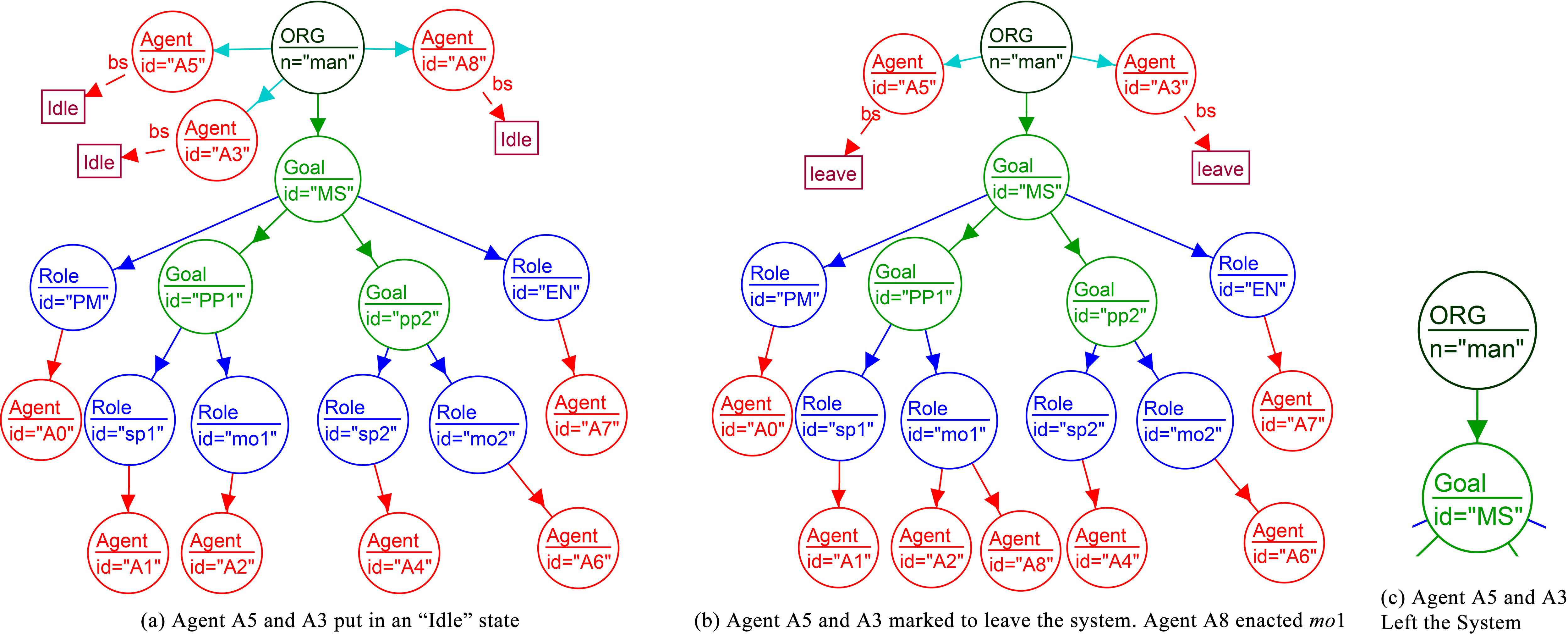
Result of the application of rules AgentEnter, and AgentSetIdle_enter.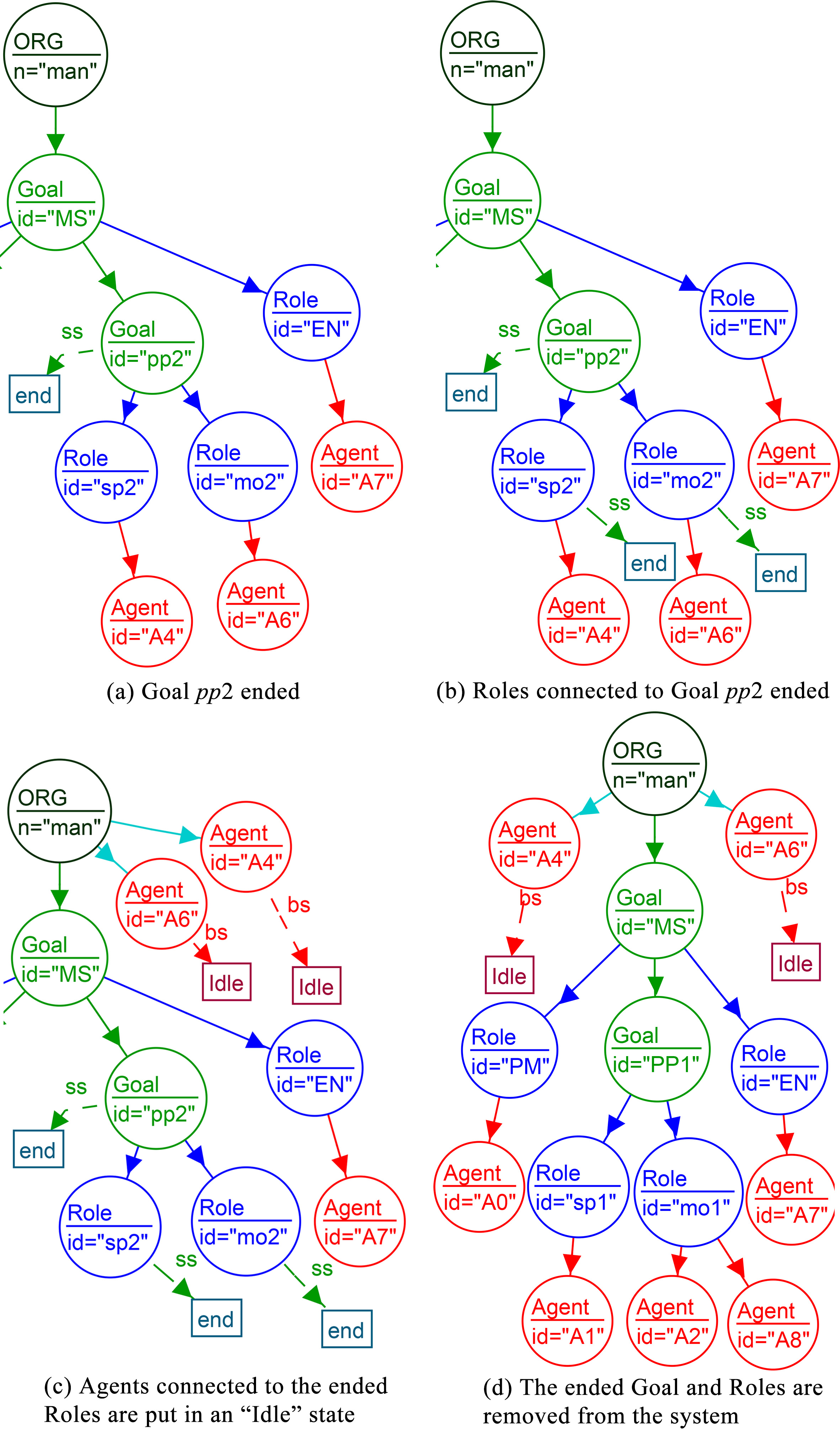
We have prepared a set of scenarios that can be applied to this system. We show the results of the application of the corresponding rules that represent the different events and the possible reorganization. The selected scenarios in this case study are: “Agent Entering the System”, “Agent Leaving the System”, and “A Goal Being Ended”. The result of the applicability of different rules for these scenarios is presented in a way, we show only the changed parts of the graph that represents the state of the system.
In this scenario: An agent named
Scenario: Agent leaving the system
In this scenario, Agents
Scenario: A goal being ended
In this scenario, a piece (piece 2) being produced by the manufacturing system is no longer in demand. Therefore, it stops its production by ending the Goal of producing this piece. The application of different rules to handle this scenario is as follow: Firstly, the rule GoalSetEnd is applied to mark the Goal
Discussion
The application of the different rules during the case study shows that our approach is easy to use and allows to represent the system (and the reorganization) in an expressive way. For instance, agents
Conclusion
We have presented in this paper an approach for reorganizing multi-agent systems using graph transformation. In particular, we have defined a type graph to represent the state of the static part of the system and a set of rules to represent the dynamic part of the system. The application of the proposed rules can modify the state of the basic elements that are used to represent a MAS organization. We have defined a formalization of the life cycle of each kind of these elements. In order to validate our approach, we have implemented the proposed type graph and the set of rules using AGG tool. We have used a concrete example related to a manufacturing system to demonstrate all the aspect of our approach. We have applied a set of scenarios of reorganization that cover all the aspect defined in our rules. The obtained results showed the efficiency of the proposed approach. As a future work, we plan to implement a simulation tool that use the proposed graph grammar and apply several scenarios of change in the system. By consequence, this tool has to show graphically how the reorganization is performed using our rules. At the conceptual level, we plan to define additional rules that allow to transform the MAS graph into a Maude specification. The latter can be used to verify at run-time that system preserve its properties after a given reorganization.
Footnotes
Responsible for the management of the organization and reorganization.
The duration depends to the chosen policy or type of the system.
Authors’ Bios