
Abstract
The relative position and metal characteristics of electrical equipment in the substation will affect the communication performance of the RFID (Radio Frequency Identification) information acquisition system. Given its environment similar to the tunnel and the multi-metal medium characteristics, an acquisition system for the state information of electrical equipment in the substation based on the radio frequency identification sensor is proposed, and a channel model of the information acquisition system is established. Also, the factors influencing the performance of the acquisition system for the state information of electrical equipment in the substation are analyzed. The experimental results show that the communication error rate of the radio frequency identification sensor can be reduced by 1∼3 orders of magnitude when the distance between the radio frequency identification sensor and the conventional sensor is less than 80 m. When the communication distance is within 25∼80 m, the vertical arrangement method of radio frequency identification sensors can reduce the bit error rate by 20% ∼40% compared with the horizontal arrangement.
Keywords
Introduction
Currently, condition-based maintenance has become the mainstream of developing electrical equipment maintenance in various countries. Overseas research on condition-based maintenance of electrical equipment is early and has gained many successful experiences in theoretical research and technical application. From the end of the 1970 s, EPRI of the American Academy of Electric Power Sciences began to study the theory of condition-based maintenance and applied it to the maintenance process of electrical equipment. In Japan, the condition-based maintenance started in the 1980 s, focusing on the condition assessment of power transformers. Many countries in Europe have also implemented the reform in this area and extended the condition-based maintenance to the operation and maintenance of electrical equipment. The concept of the smart grid was taken as a symbol to gradually promote the optimal management of the power grid to its strategic position in various countries. In 2008, the United States Department of Energy submitted a report on the smart grid system on the analysis of its current situation and challenges. Currently, over 50% of the power companies in the United States have implemented condition-based maintenance of electrical equipment, and the maintenance of electrical equipment in China has gradually changed from regular maintenance to condition-based maintenance. However, most of the power enterprises still focus on routine maintenance. There is still a big gap between the theoretical and technical research of various aspects and that of foreign countries.
In the application of condition-based maintenance of electrical equipment, equipment management system based on computer network technology has been widely used in the United States, Canada and other countries, mainly for accident analysis and system early warning, such as Integrated Maintenance System. They use computer network technology such as Intranet, Internet and GIS to integrate condition monitoring, fault alarm and maintenance, to improve the level of equipment supervision and management. The application of condition-based maintenance in China mainly focuses on the on-line monitoring devices of electrical equipment such as oil chromatograph on-line monitor and partial emission infrared thermal imager. With the reform of the electric power system, condition-based maintenance of electrical equipment has achieved great development in China, and some maintenance management software and systems have emerged. But generally speaking, it is still in the initial stage of exploration, and there are few available results in practice. Therefore, fish need to establish a complete condition-based maintenance system and develop the corresponding system. The intelligent substation is the key “Support point” and carrier for the smart grid information interaction. The Radio Frequency Identification (RFID) technology can implement the active sensing and the communication functions to accurately acquire the node and the network information (Mosalam et al., 2016; Li et al., 2017) and comprehensively improve the performance level of the information acquisition equipment. It can meet the requirement for the accurate acquisition of the state information of electrical equipment in the substation and the network interaction. The wireless transmission channel environment can directly affect the signal transmission performance of the acquisition system for the state information of electrical equipment in the substation A (Liu et al., 2010; Chen et al., 2012). A number of the electrical devices are arranged to constitute an environment similar to the tunnel, where multiple reflections and diffraction phenomena will occur during the radio wave propagation, resulting in a severe multipath effect. This can affect the read performance of the conventional sensors (Ma et al., 2015; Topaz, 2010). Hence, the electromagnetic propagation characteristics of the acquisition system for the state information of electrical equipment in the substation shall be analyzed to establish a useful system channel model, and further analyze the performance of the acquisition system for the state information of electrical equipment in the substation (Mohammadi et al., 2012; Pal et al., 2018). Domestic and foreign scholars have carried out many studies on the RFID sensors. Through the field experiments, the external factors that can affect the performance of the information acquisition system are analyzed. However, no relevant theoretical derivation or system modeling has been carried out (Li et al., 2010; Li et al., 2013). The relationship between the backscatter modulation method of the RFID sensors and the energy captured by the label is analyzed. And it is pointed out that the channel fading of the RFID sensors is different from that of the traditional Rayleigh distribution model (Mohammadi and Tehrani, 2014), focusing on discussing the effect of the transmit power of the sensor on the performance of the RFID sensor. A number of the electrical devices in the substation form an environment similar to the tunnel, and the multipath interference during the radio wave propagation can seriously affect the quality of communication, resulting in the inter-symbol interference and deep fading of the received signal. When there are metal materials in the environment, the multipath phenomenon is particularly severe (Gilvanejad et al., 2013; Li et al., 2010). The casing of electrical equipment in the substation is mostly made of metal. Hence, the influence of metal materials on the RFID sensor channel shall be considered (Ranasinghe et al., 2014; Lee et al., 2015).
In this paper, given specific environmental characteristics of the substation, an acquisition system architecture for the state information of electrical equipment in the substation based on the RFID sensor is proposed, and a RFID sensor channel model that is suitable for the substation environment is established. Also, the factors such as the installation location, quantity and placement method, etc. of the RFID sensors on the channel performance of the acquisition system for the state information of electrical equipment in the substation are analyzed. The experimental verification results show that the model established in this paper is consistent with the actual situation (Chen et al., 2011).
Acquisition system architecture for the state information of electrical equipment in the substation
The overall scheme design of the application of RFID sensor tags in substation on-line monitoring is composed by third parts. Firstly, the integration of electrical information sensor and RFID tag is carried out. Subsequently, the installation of the tag and reader is conducted based on the communication characteristics. Finally, the debugging and installation of communication manager and background server are completed. The integration and selection of measurement terminals shall focus on the requirements of detection quantity, installation environment and communication effect. The installation of tag and reader mainly considers the stability of communication, and finally completes the debugging and installation of communication manager and background server, so that all the data of the reader can be uploaded to the background server through the communication manager. Managers can view the real-time operation of each measuring point of each device via the software (Chiba and Nara, 2014).
The operating state of electrical equipment directly affects the safety and stability of the operation of electrical equipment. Different functions of the RFID sensors have various automatic sensing and recognition capacities. The RFID sensor is applied to the acquisition system for the state information of electrical equipment in the substation, which can collect the operating status information of electrical equipment and the environmental information to improve the real-time performance, accuracy and reliability of the information acquisition system. When the reader sends a message acquisition command, the RFID sensor in the active radiation area of the reader sensor is activated, which sends back the perceived information (temperature, humidity, vibration and acceleration, etc.) and the label’s own data to the reader and upload it to the monitoring center (Kim, et al., 2012). Hence, the personnel in the monitoring center can collect the state and operating situation of the equipment in the substation in real time. In this paper, the acquisition of the temperature information of the equipment in the substation is adopted as an example, and the system architecture is shown in Fig. 1 as follows.
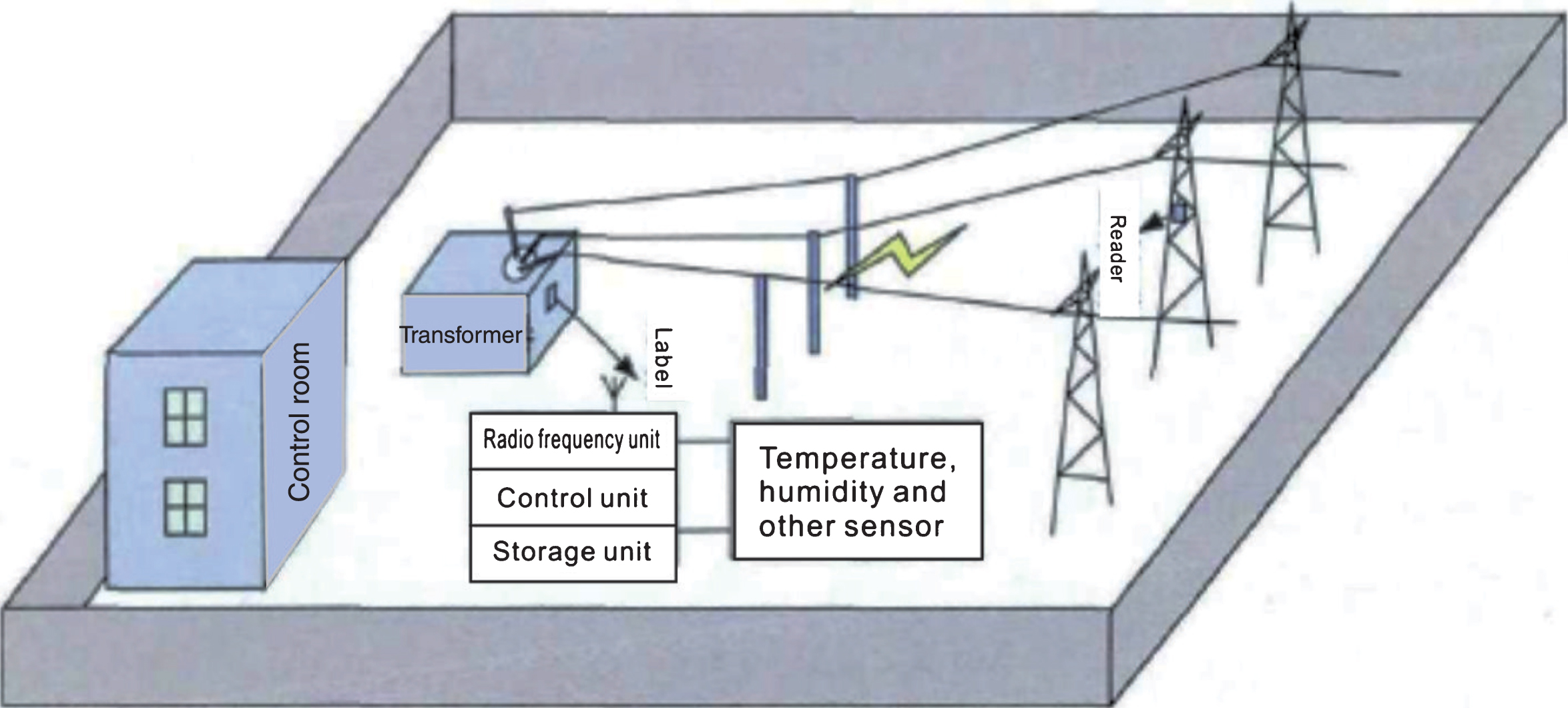
Acquisition system for the state information of the electric transmission and transformation equipment in the substation.
According to the geometric characteristics of the application environment, the geometrical shapes of the propagation channel include the closed type (such as the arch tunnel, horseshoe tunnel and rectangular tunnel), free space type (such as the electromagnetic wave caged in no other objects similar to the wave shape object other than the ground), semi-closed type (such as the L shaped and U shaped channel), etc. Given the layout characteristics of electrical equipment in the substation, the electromagnetic wave propagation channel is a non-fully closed tunnel shape, which can be regarded as a U-shaped channel formed by the ground and both sides of the metal wall (Ranasinghe et al., 2014). When the electromagnetic wave is in a U-shaped channel, one or several reflections and diffractions will occur on the ground and the side of the metal wall. The maximum allowable transmit power of the RFID system is minimal. Considering the propagation path loss, the secondary and multiple reflections are generally very weak. Meanwhile, when the electromagnetic wave passes through the rough metal surface, scattering phenomenon will occur, and the intensity of the electromagnetic signal will decline sharply. Therefore, in this paper, the electromagnetic wave reflection in the second time or more times is ignored. The electromagnetic wave propagation in the U-shaped channel is shown in Fig. 2 as follows (Zhang, 2008), where r1 represents the direct propagation path of the electromagnetic wave, r21 and r22 represent the electromagnetic wave reflection path that occurs on the side of the two metal walls, respectively, r3 represents the electromagnetic wave emission path with the ground as the reflection surface, H represents the height of the RFID sensor, and h represents the height of the RFID sensor.

Simplified scene of the electromagnetic wave propagation in the substation.
To reduce the requirement of sampling rate for the localization algorithm of partial discharge based on time-delay sequence, this paper analyses the electromagnetic field propagation characteristics of partial discharge radiation and the antenna factor of the receiving antenna. A three-dimensional coordinate system is established in the substation space based on the theory, and the relationship between the peak value of the electromagnetic wave received by the antenna and the position of the partial discharge source and antenna is deduced. A partial discharge localization algorithm based on electromagnetic wave attenuation similar to RSSI is proposed. The algorithm only requires extracting the peak value of the signal without calculating the time delay sequence of the signal. The peak value of the signal can be extracted by peak holding and detection method. The method is simple and can be accurately collected at a minimal sampling rate so as to reduce the cost of the signal acquisition system (Yusof et al., 2015). According to the simplified scene as shown in Fig. 2 as follows, there are three reflected rays emitted by the RFID sensor: one ray is the ground reflected ray and the second is the ray reflected on the side of the metal wall. As the ground is different from the metal wall in the material (metal is a benign conductor), the electromagnetic wave reflection coefficients of varying polarization modes are very different. According to the Friss equation, the electromagnetic wave loss of the information acquisition system in the substation is as follows
In the equation, N represents the number of electromagnetic waves reflected rays in the information acquisition system of the substation. In this paper, N = 3, L i represents the path length of the i-th ray, VL i represents the path difference between the i-th ray path and the free space path, which is the reflection coefficient of the i-th ray.
Multiple electrical devices in the substation constitute an environment similar to the tunnel, in conjunction with the presence of a large number of metal materials, the multipath interference during the radio wave propagation is particularly severe, which has dramatically affected the wireless communication quality of the information acquisition system and reduced the system performance. To improve the reliability of the system, the RFID sensor can be adopted. The acquisition systems for the state information of electrical equipment in the substation can be divided into the single station model and the dual station model, where the transceiver radio frequency module and sensor are applied in the single station model, and the separated transmitter/receiver module and sensor are adopted for the dual station model (Barge et al., 2014). In this paper, the acquisition system for the state information of electrical equipment in the single substation is taken as an example, as shown in Fig. 3 as follows. The relationship between the active forward channel h
q
(t) and the backscattered signal h
s
(t) is as follows
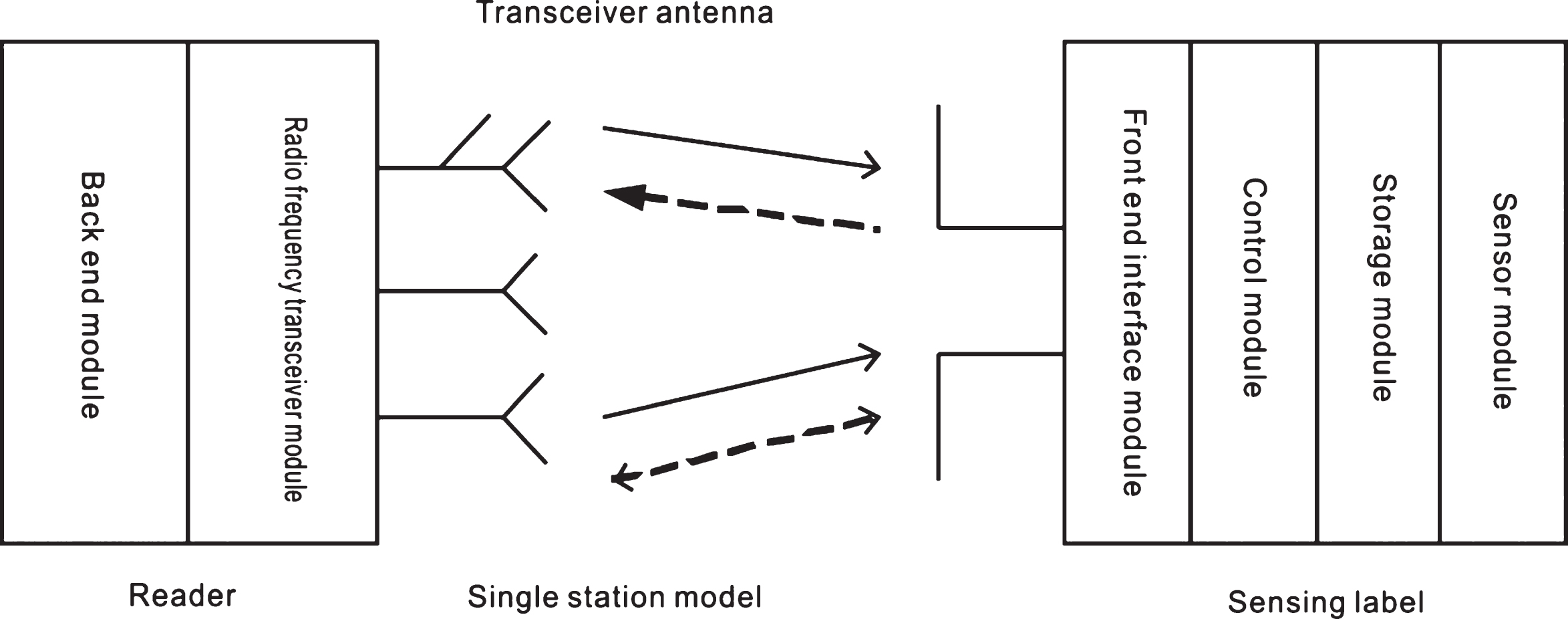
Acquisition model for the state information of electrical equipment in the substation.
Based on the ray tracing method, the system channel impulse response can be obtained as follows
Where, g (t) represents the ray tracing response. Assuming that the line of sight propagation amplitude of the ray is 1, R i , τ i and φ i represent the amplitude, delay and phase of the i-th ray, respectively.
Its narrowband frequency response is as follows
Then the RFID channel matrix can be obtained as follows
Given the line of sight propagation, the value taken for n in the Equation (5) shall start from 0, where h ij (t) represents the channel response between the i-th transmitting sensor and the j-th receiving sensor.
In the acquisition system for the state information of electrical equipment in the substation, to obtain the maximum diversity gain, the maximum SNR is used to calculate the weighting coefficient, and the weighting coefficient is as follows:
In the equation, W(q,s) (t) represents the weighting coefficient between the q-th forward link and the fs-th backscatter link, and h T represents the complex conjugate transposed matrix.
In the practical applications, when the continuous carrier signal sent by the RFID sensor is activated, the signal waveform received by the RFID sensor is as follows:
In the equation, L
q
represents the forward activation distance, Pt-reader represents the power of the transmitting sensor, Gt-reader represents the gain of the transmitting sensor, G
tag
represents the gain of the RFID sensor, x (t) represents the continuous carrier signal, ξ represents the path loss factor, and n (t) represents the Gaussian white noise vector. Combined with the Equation (6), the receiving power of the RFID sensor can be obtained as follows
The radio frequency signal waveform of the RFID sensor in the backscattering is as follows (Li et al., 2010)
In the equation, L
qs
represents the reverse recognition distance, β
p
represents the ratio of the RFID sensor to the actual scattered signal, M represents the modulation factor of the RFID sensor, and Gt-reader represents the sensor gain received by the RFID sensor. Hence, the following can be obtained
In the equation, Φ (f) represents the power spectrum of the backscattered signal, BM represents the receiving filter bandwidth. Combined with the Equations (6, 8 and 9), the SNR (SNR) of the signal received by the RFID sensor is as follows
In this paper, mainly the influence of the distance L between the RFID sensors on the performance of the system is considered. Assuming that the recognition distance of the two is L, then L2 = L
qs
L
a
can be obtained; assuming that N
t
= N
r
, the maximum signal t -noise ratio of the signal received by the acquisition system for the state information of electrical equipment in the substation can be obtained as follows
The SNR of the RFID sensor Nakagami-m channel is as follows
In the equation, m′= m (Tr (D)) 2/Tr (D) 2 represents the distribution parameter, Tr (D) represents the trace of the matrix D, and D represents the normalized channel correlation matrix.
Hence the bit error rate (BER) of the acquisition system for the state information of electrical equipment in the substation can be obtained as follows:
The installation height, quantity, placement position and other factors of the RFID sensor in the acquisition system for the state information of electrical equipment in the substation can affect the receiving power of the system, thus affecting the bit error rate of the acquisition system for the state information of electrical equipment in the substation. In this paper, the changes in the system error rate set under different parameters and the distance of the RFID by the RFID sensor is used to evaluate the performance of the system (Deng et al., 2008). The Matlab cftool toolbox is used to carry out fitting on the simulated channel model data, and the influence of different parameter changes on the performance of the acquisition system for the state information of electrical equipment in the substation is obtained. The test equipment and simulation parameters are shown in Table 1. The status information acquisition system of electrical equipment in substation is shown in Fig. 4. In the simulation and actual test, the RFID sensor is located in the center of the U-shaped aisle, the working frequency band of the information acquisition system is 2.4 GHz, the RFID sensor is a circular polarization sensor with a gain of 6dBi, and the conventional sensor is a half-wave oscillator sensor with a gain of 1dBi as follows.
Simulation and parameters of the experimental model
Simulation and parameters of the experimental model

The status information acquisition system of electrical equipment in substation.
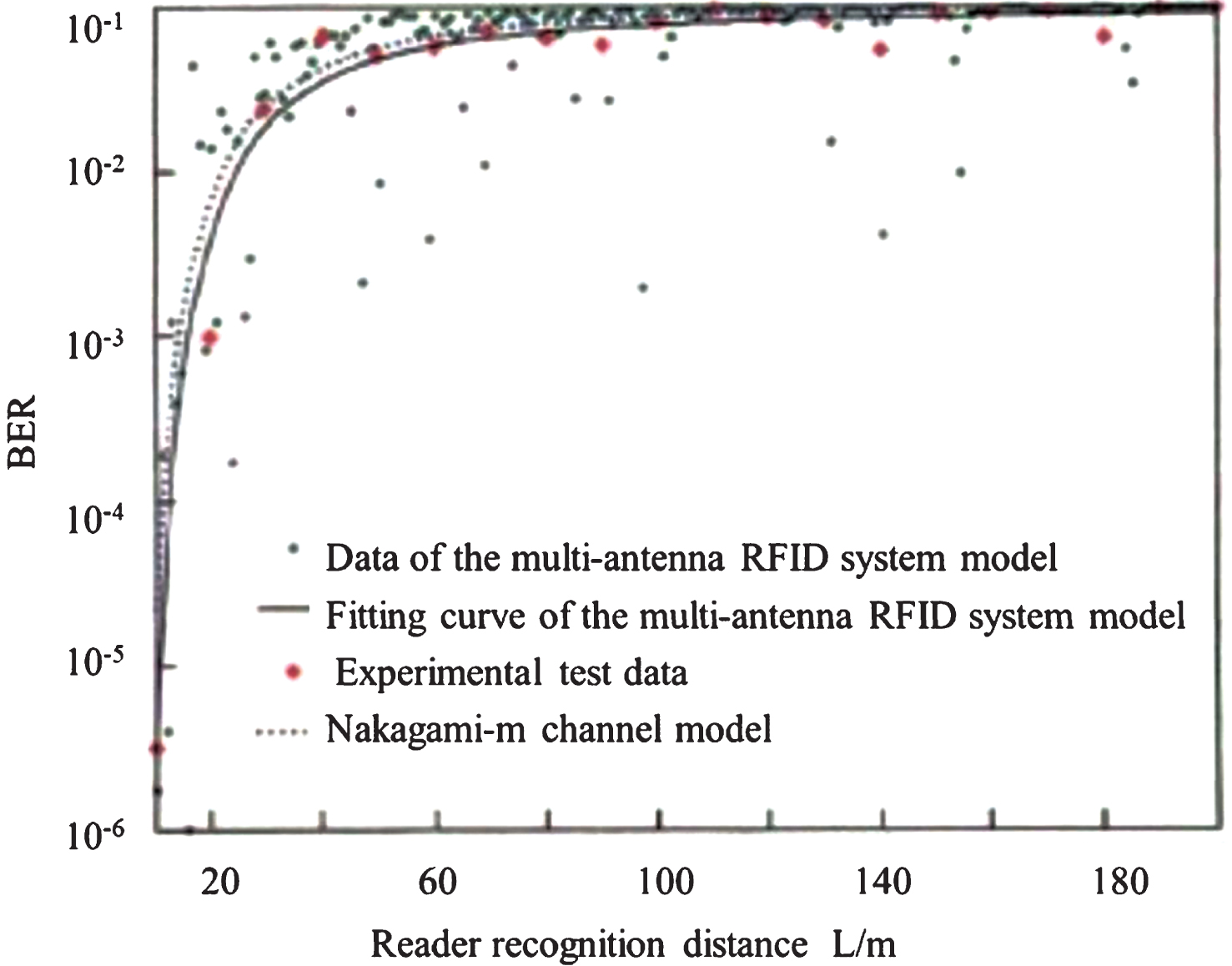
The results of the comparison between the simulation channel model based on the Matlab cftool tool and the Nakagami-m channel model are shown in Fig. 5. Figure 5 shows that the RFID sensor channel model based on the ray tracing and the Nakagami-m RFID sensor is constructed in the simulation environment of the substation, where the channel model is similar, and the test data error is less than 10–1 in the order of magnitude. Compared with wireless sensor networks, the advantages of RFID technology lie in its low cost and a large number of measurement nodes. Because the measurement nodes of wireless sensor networks have the functions of information forwarding and routing, they have more complicated structure, higher energy consumption and higher cost thanthe sensor tags. Also, the multi-hop transmission of information will cause considerable communication delay, which limits the number of multi-hop and nodes in the network. Attributing to the simple network structure and sophisticated anti-collision algorithm of RFID system, it is possible to accommodate more measurement nodes.
Simulation and experimental verification.
The comparison of the bit error rate between the RFID sensor and the conventional sensor system is shown in Fig. 6 as follows. Figure 6 shows that, after the RFID sensor is used, the greater the number of sensors is, the smaller the bit error rate of the system is; within the range of 0∼80 m, compared with the RFID sensor and the conventional sensor system, the error rate of the RFID system is reduced by about 1 to 3 orders of magnitude, and the system error rate can be significantly reduced. As the distance between the RFID sensor and the conventional sensor increases, the gap in the bit error rate of the RFID systems with different numbers of sensors is gradually reduced. When the recognition distance of the RFID recognition sensor is greater than 150 m, the increase in the number of the RFID sensor reception amount has no significant effect on improving the bit error rate of the system as shown in the following.
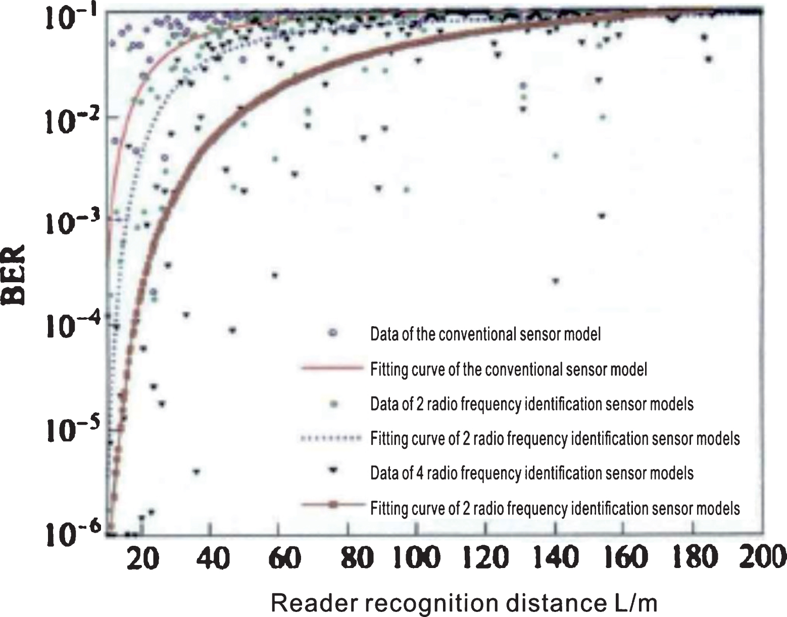
Effect of quantity on the performance of the system.
The relationship between the bit error rate of the acquisition system for the state information of electrical equipment in the substation and the height of the RFID sensor is shown in Fig. 7. The “General design catalogue for 35 kV∼220 kV transmission line tower” suggests that the height of the tower (the distance of the power line at the lowest site on the tower from the ground) can be divided into a few grades as follows in general: 12 m, 15 m, 18 m, 21 m and 24 m. Assuming that the power line is distributed in an equilateral triangle. Considering that the distance from the power line at the lowest height of the tower to the center line of the tower is 2.3∼2.8 m, and 2.5 m is taken at this point. The safe distance of the RFID sensor from the power line at the lowest site of the sensor is 5 m (a certain safety margin is reserved), hence and the height of the RFID sensor from the ground can be obtained as 18.67 m. For the convenience of analysis, the height of the RFID sensor is 18 m, 15 m and 12 m from the ground. Figure 7 shows that the higher the height of the RFID sensor is, the smaller the bit error rate of the system is. When the height of the RFID sensor increases, as the propagation distance of the reflected signal is farther than that of the direct signal and the path propagation loss is large, the signal interference caused by the multipath effect is weakened, which allows the receiving of the useful signal in the received signal.

Effect of the height of the RFID sensor on the performance of the system.
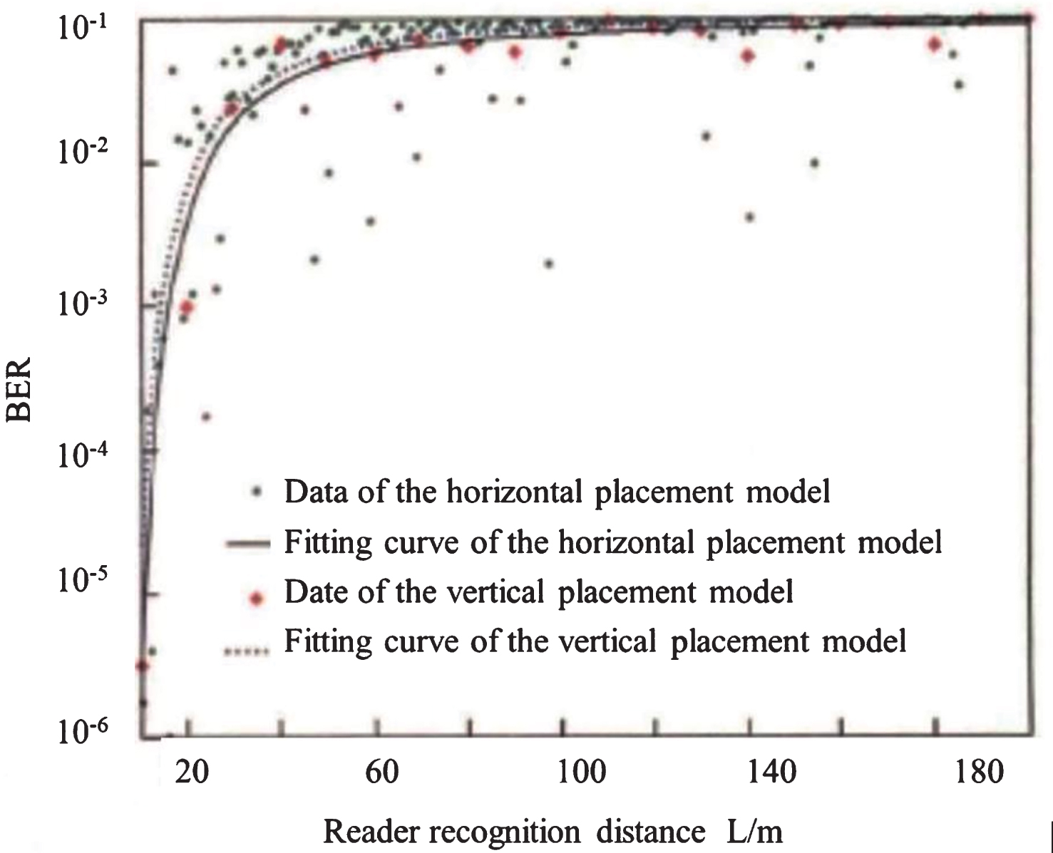
RFID sensors have multiple layouts, as shown in Fig. 8, which include the horizontal arrangement of several sensors (referred to as horizontal arrangement for short), vertically arrangement of several sensors (referred to as vertical arrangement for short). In Fig. 8, D l represents sensor spacing. The horizontal arrangement of the sensor and the change in the system error rate with the vertical arrangement are shown in Fig. 9. Figure 9 suggests that when the distance between the RFID sensor and the conventional sensor is [25 m, 80m], the bit error rate in the vertical arrangement is reduced by 20% ∼40% compared with that in the horizontal arrangement. When the distance between the RFID sensor and the conventional sensor is greater than 120 m, the arrangement of sensors has little effect on the bit error rate of the system. Considering that the effective range of the RFID sensor of the acquisition system for the state information of electrical equipment in the substation is usually less than 100 m, the vertical arrangement should be adopted for the system sensor as much as possible.
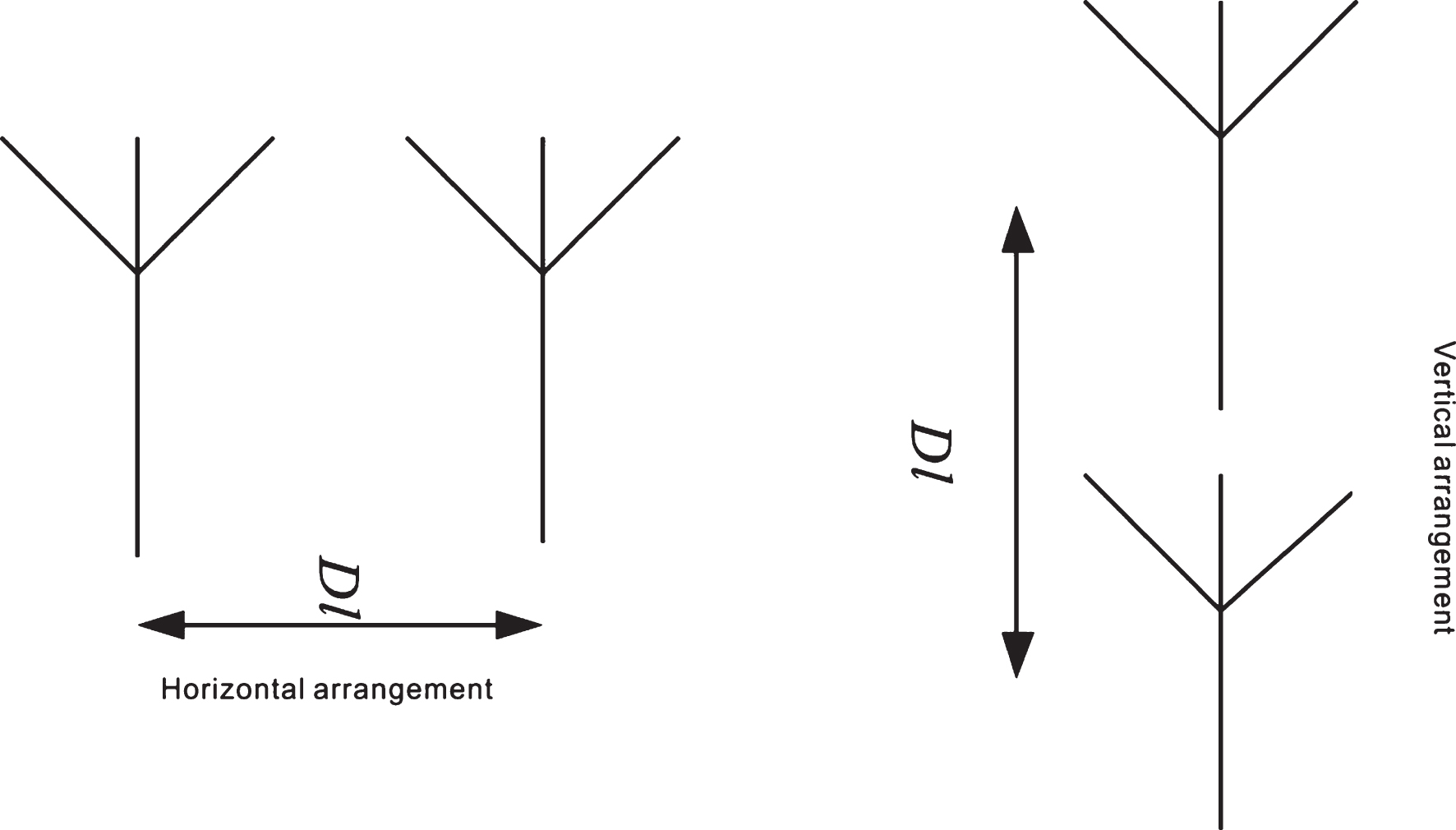
Sensor layout.
Effect of sensor placement position on the performance of the system.
To meet the needs of accurate acquisition of the state information on the electrical equipment in the substation and the network interaction, an acquisition system architecture for the state information of electrical equipment in the substation based on the RFID sensor is proposed in this paper. Considering the environment similar to tunnel and the multi-metal medium characteristics in the practical application scenes of the substation, an RFID sensor solution is proposed. Given the multipath interference problem, a channel propagation model for the acquisition system for the state information of electrical equipment in the substation based on the ray tracing method is established. Also, the effect of different factors on the bit error rate of the system is analyzed. The simulation and experimental results can provide a reference for the construction personnel. In the next step of work, the effect of the electromagnetic environment in the substation on the system channel will be studied.