
Abstract
In India, there are about 1.5–2 million estimated cancer cases. Early detection can significantly reduce the mortality rate. This paper focuses on planning an ultra-wideband directional Microwave imaging system to detect cancer cells. Microwave imaging uses the scattering wave or reflected wave that arises from the contrast in dielectric properties between normal and malignant breast tissues. Microwave breast imaging, which is non-invasive and harmless to human, offers a promising alternative method to mammography. A compact, ultra wideband (UWB) planar antenna for the Microwave thermography system is designed and simulated using two commercial software, CST Microwave studio and HFSS stimulators. The proposed technique depends on the significant contrast in the dielectric properties of the normal and tumor tissues.
Introduction
Breast cancer has ranked number one cancer among Indian females with age adjusted rate as high as 25.8 per 100,000 women and mortality 12.7 per 100,000 women (Malvia et al., 2017). However if breast cancer is detected early enough, the five-year survival rate is over 90%. A recently U.S Institute of medicine (IOM) review that the current state of x-ray mammography technique still mostly effective for breast diagnoses but have exposure to ionizing radiation, not enough sensitive to detect tumor and discomfort for patients (Daud et al., 2014). They also suggest other technologies for breast cancer screening (Committee on Technologies for the Early Detection of Breast Cancer, 2001; Fear et al., 2002). They also had studies for other methods such as ultrasound, MRI and PET scan where have problems in accuracy, high cost and need long time to diagnosis regular screening purpose (Fear et al., 2002). This evidence is further strengthened the weakness of X-ray mammography (Xu et al., 2013). However if the breast cancer is detected early enough, the five-year survival rate is over 90% (A. C. Society, 2016; K. B. C. Society, 2014). Thus, regular checkups and early detection of breast cancer are crucial.
Microwave imaging can obtain an image quickly compared to other imaging methods (Fear et al., 2003). Microwave Ultra-wide Band imaging is presenting a promising technology for wireless communication with very high speed, high preciseness radars, and imaging systems. This application involves transmitting UWB signals through the surface of the tissue and records the backscattered signals from different locations. The proposed UWB antenna is stimulated by computer simulation software (CST) software and satisfies the VSWR < 2 requirements from 8.2 GHz to v19 GHz. The designed antenna has a simple configuration with a standard square-shaped radiating patch and small size (Malvia et al., 2017).
Literature survey
(Daud et al., 2014) This paper explains the techniques used for tumor detection using microwave imaging MIST technique and increasing the spatial resolution at microwave frequencies. (Fear et al., 2002). The author uses the electrical properties of the normal and malignant breast tumor with the image reconstruction algorithm for confocal microwave imaging. (Liu et al., 2016). The author used a H shaped antenna structure with a radiation efficiency of 90.95%. (Shrestha et al., 2012). This paper presents a flexible antenna in contact wit human skin with S11 = –19 dB at 2.45 GHz.
Proposed method
We propose a miniature rectangular printed antenna for microwave medical imaging applications. The antenna has ordinary rectangular radiating patch, therefore displays a good Omni directional radiation pattern. In this paper, design and analysis of U-T-shaped Meta-material antenna has been presented. It shows negative permittivity and permeability characteristics. The Meta-material array is embedded in the substrate of the rectangular Micro-strip patch antenna. Upon incorporation, directivity increases by 24% and gain increases by 18%. The proposed antenna resonates in s band of the electromagnetic spectrum and provides low VSWR of 1.01. The dimensions of radiating patch of proposed Micro-strip patch antenna design are 17mm*22 mm.
Flow diagram
The proposed model consists of square radiating patch with micro strip step feeding and a partial L-shaped ground. To enhance the bandwidth, gain and directivity we have introduced T-shaped slot in the path. The dimension of our proposed antenna is 16×18 mm.
There are many different structures of directional antenna, but basically they consist of four parts namely, the patch, A dielectric substrate, A ground plane, A feed line. In this paper we focus on square radiating patch. The metallic patch is available in different configurations. However the rectangular and circular patches are the most popular because of ease of analysis and fabrication, and their attractive radiation characteristics, especially low cross polarized radiation
Feeding techniques
One of the most important parts of the directional UWB antenna is feeding structure. Directional antennas can be fed by a variety of methods (Liu et al., 2016). These methods can be classified into two categories are contacting and non-contacting. Here we use micro strip feeding.
Micro strip feeding
In micro strip feeding technique, a conducting strip is connected directly to the edge of the micro strip patch. The purpose of the inset cut in the patch is to match in the impedance of the feed line to the patch without the need for any additional matching element (Committee on Technologies for the Early Detection of Breast Cancer, 2001). This is achieved by properly controlling the inset position. Hence this is an easy feeding scheme, since it provides ease of fabrication and simplicity in modelling as well as impedance matching (Fear et al., 2003).
Design of ground plane
The basic directional antenna element is comprised of a partial ground plane. Here the material used for ground plane is copper annealed. The specifications of copper annealed are listed above.
Design equations
Width of the rectangular patch
Where, Co-speed if light (3×1011mm/s)
ɛr-dielectric constants (2.2)
fr-centre frequency (in GHz)
Length of the patch
Where, ɛeff- effective dielectric constants.
Width of the field
Where,
Directivity
Gain
Fabricated directional antenna with t-shaped slot
In our proposed model a rectangular patch of dimension 16*18mm With T-shaped slot and step feeding is introduced.
Surface current distribution
The maximum value of the current distributed is 112A/m with the centre frequency of 11GHz.
Radiation pattern
The below diagram give the far field pattern at f = 11GHz, which give the directivity = 8.9dbi and gain = 6.8db at far-field f = 11GHz.
Testing results
The tested results of our proposed T-shaped patch antenna is shown below
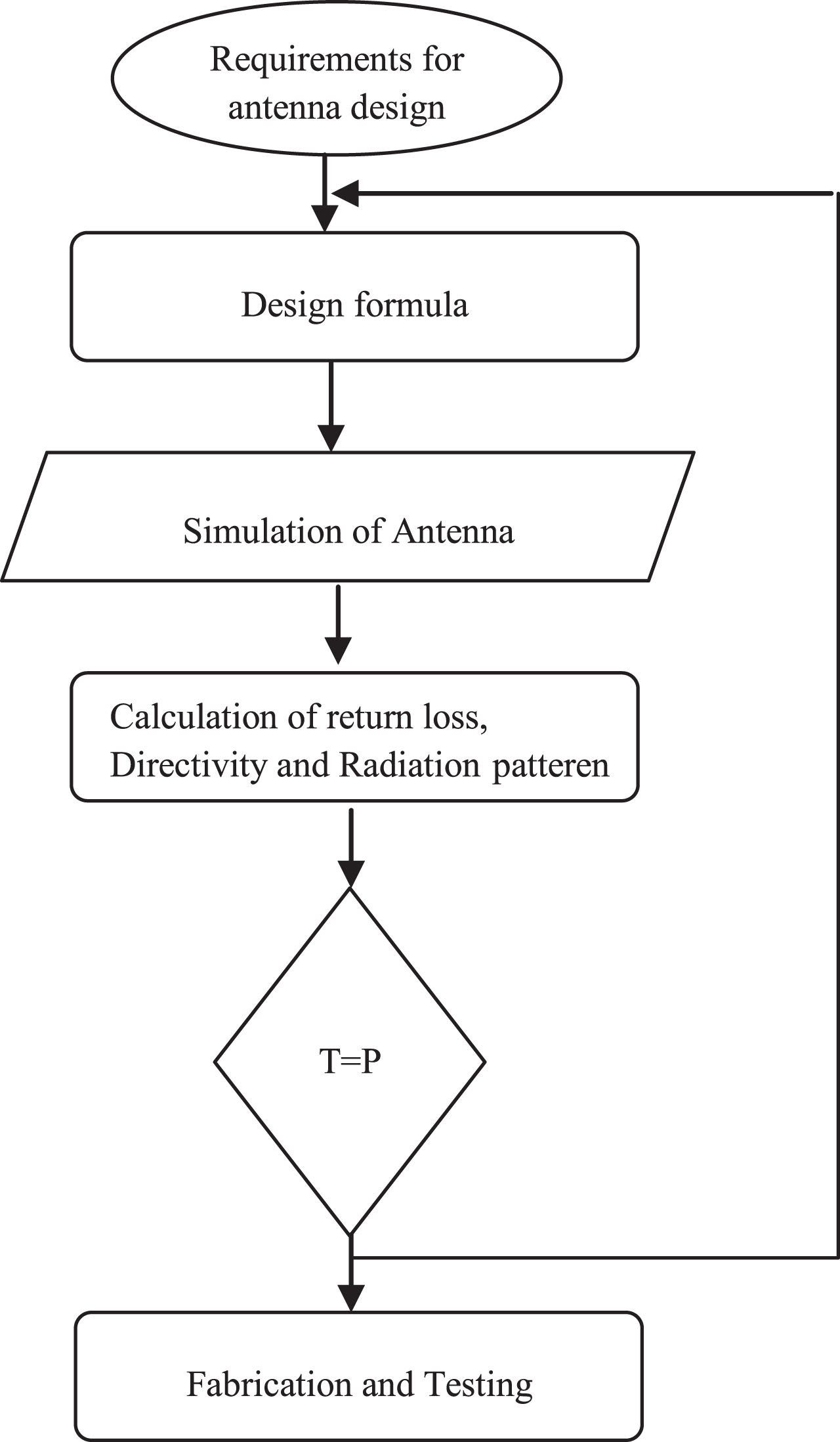
Design flow.
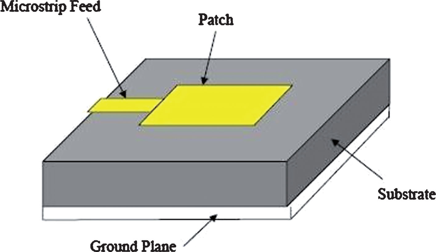
Microstrip patch antenna.
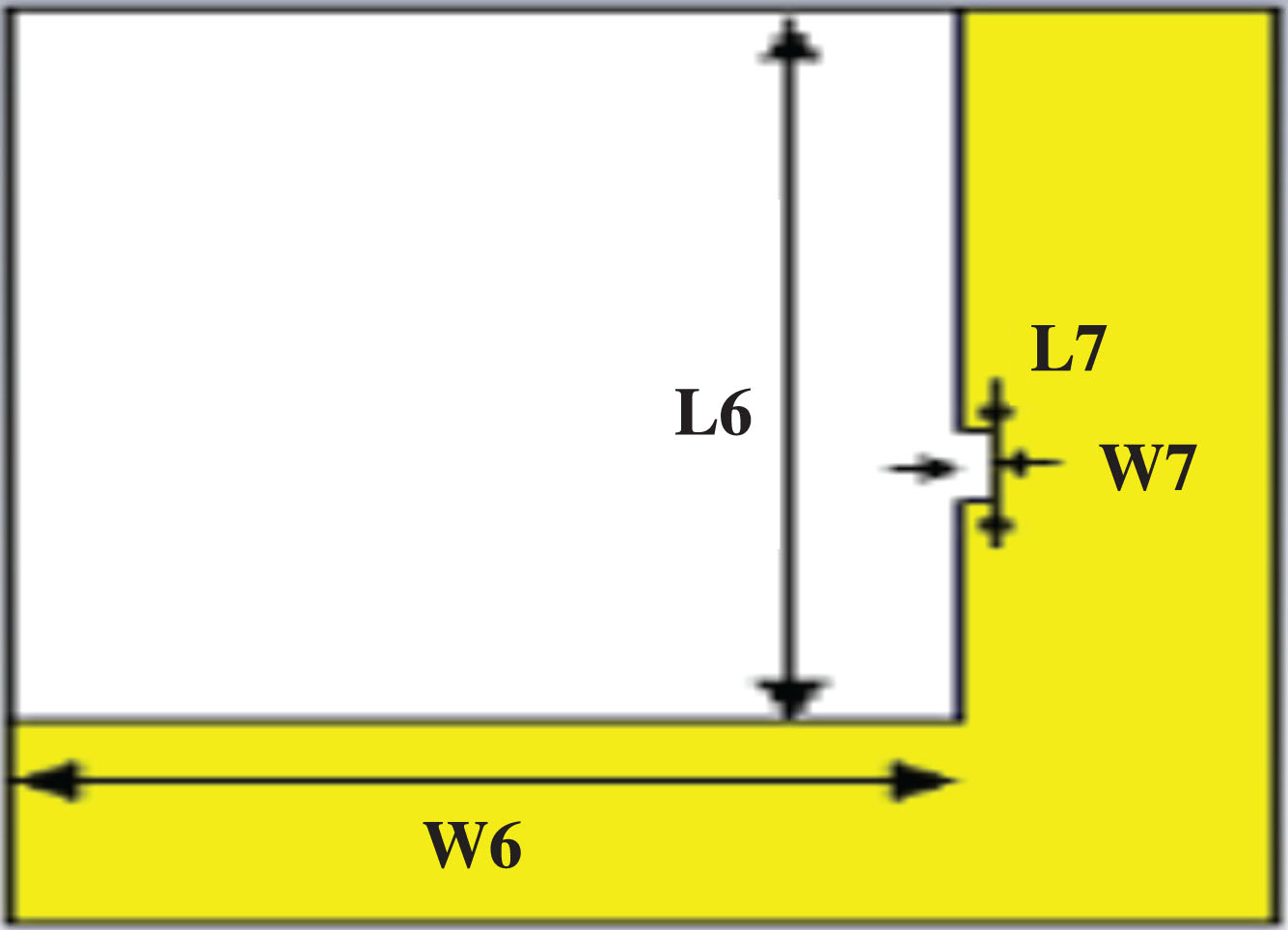
Ground plane.
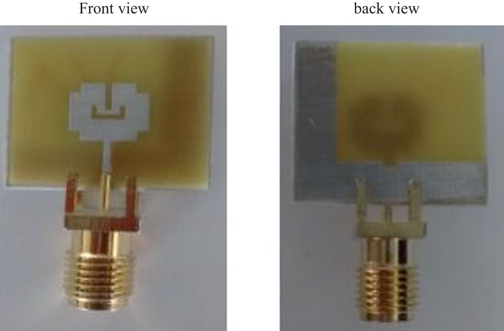
Directional antenna with T-Shaped Slot.
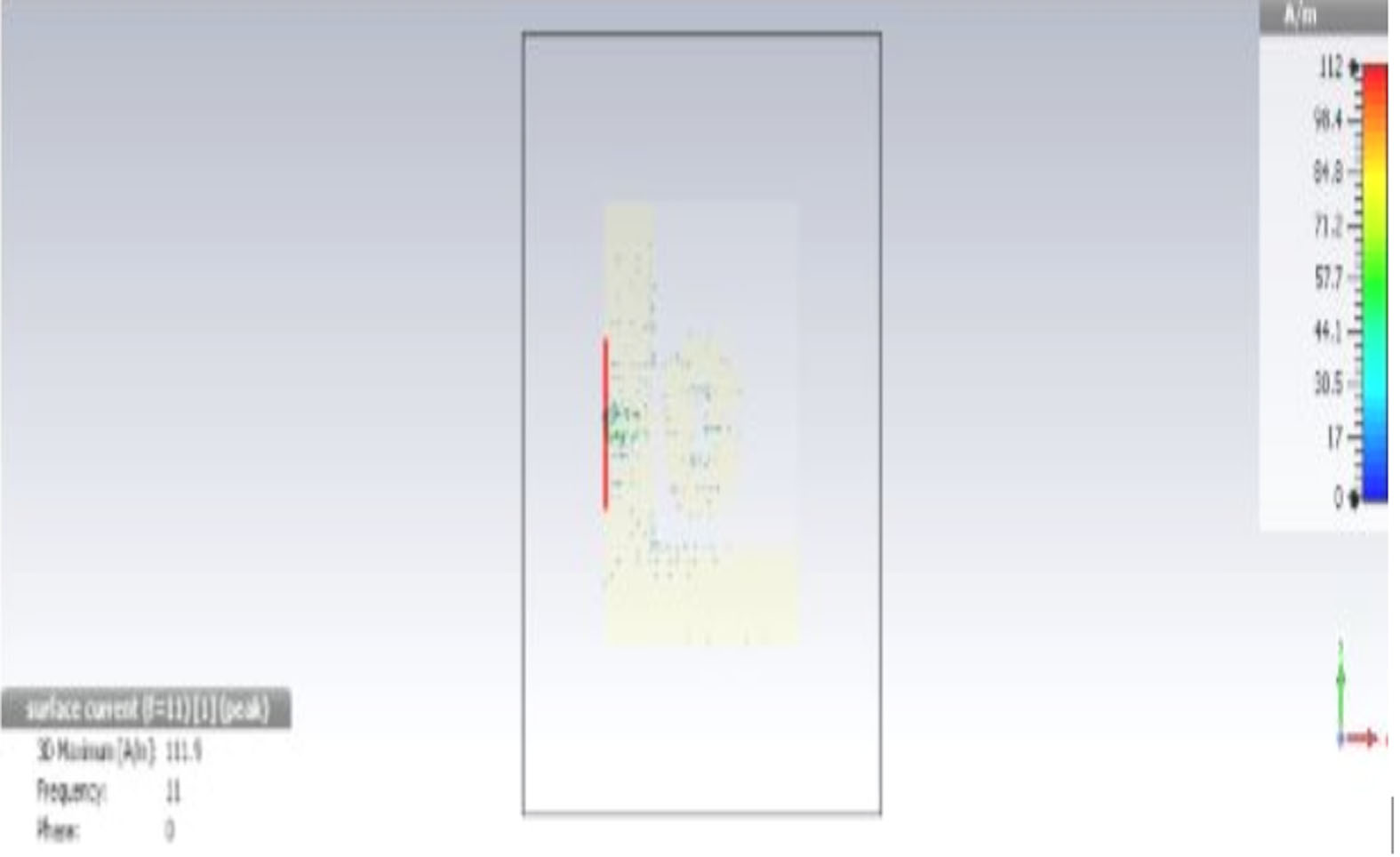
Surface current distribution of proposed antenna.

3D Radiation Pattern.
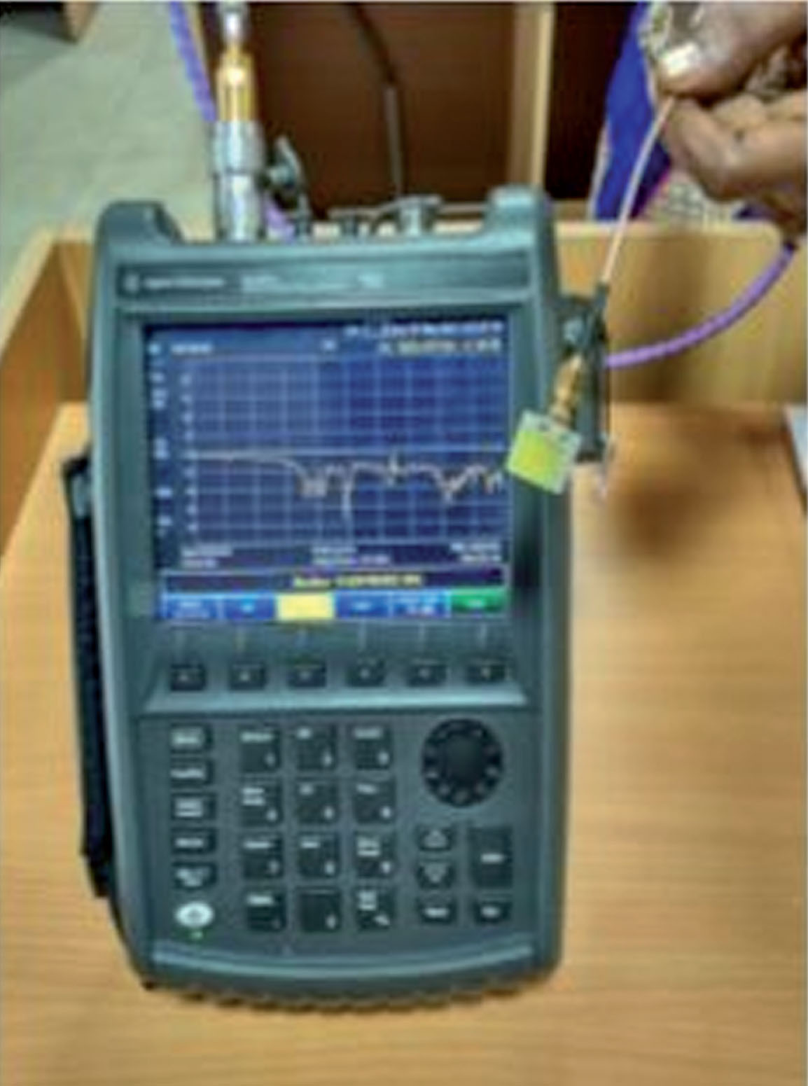
Testing result in network analyzer.
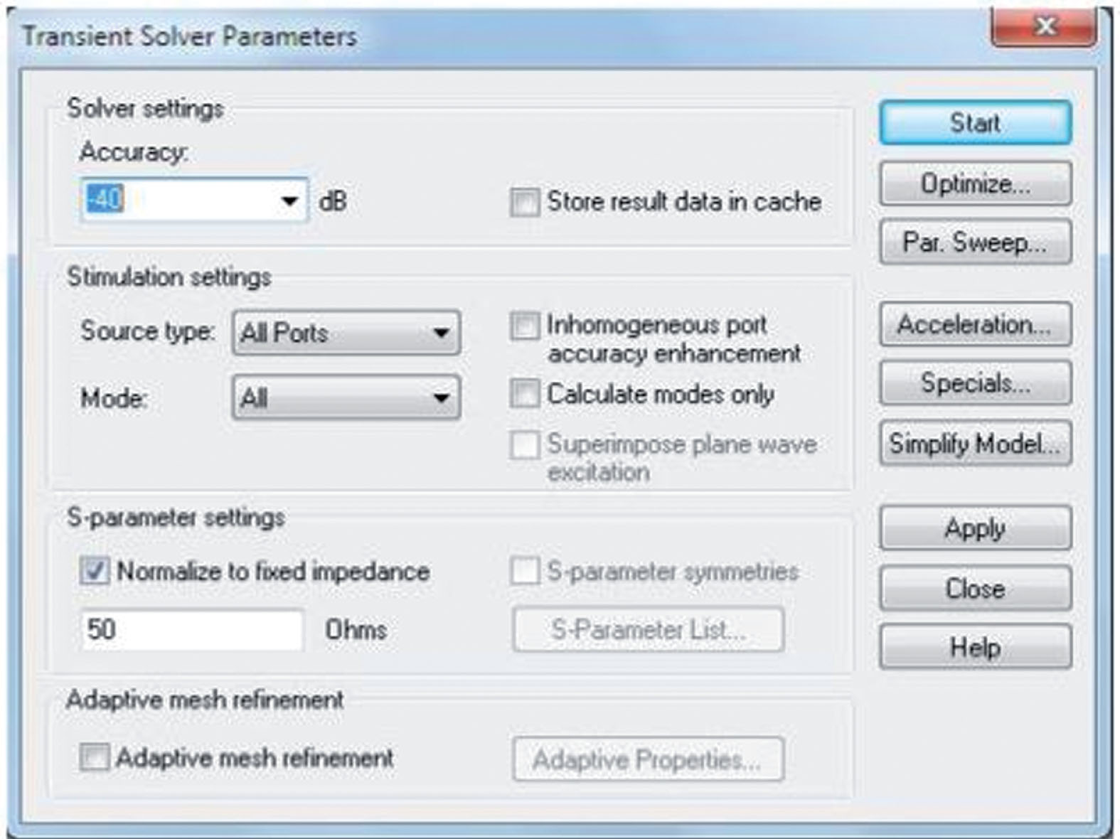
ADS Solver setup.
The outstanding characteristics like compact size, less cost, wider bandwidth, gain and directivity suits our purposed application of cancer detection. The proposed antenna consists of High directivity (9dBi) Wider bandwidth (10.2 GHz) High gain (7.5 dB) The frequency range is 8.2 – 19 GHz
Future work
Future work on this project can be done on the area of minimizing the surface current of the antenna using various Defective Ground Structures (DGS) and EBG (Electromagnetic Band Gap) design. Also the gain of the antenna can also be improved with these designs by appropriately constructing the DGS and EBG on the ground plane.