
Abstract
The development of RFID enabled intelligent localization system in the workshop is of great importance for reducing the operation cost, increasing production efficiency and improving management capabilities. From the aspects of feature extraction of RF fingerprint and localization algorithm, the scheme of mobile target tracking based on the fusion of inertial navigation and fingerprinting is explored. The deep neural network is used to establish the nonlinear relationship between fingerprint and coordinates. After the initial position of the mobile robot is obtained, Kalman filter is used to fuse the data collected by IMU and wheel encoder. Experimental results show that the proposed method is feasible and be able to track the mobile robot accurately.
Introduction
Modern manufacturing workshops are facing the development trend of digitalization, networking and intelligence. Closely related to the real-time monitoring of the production site is the Internet of Things (IoT) technology with wireless sensor network as the core. The Internet of Things technology, especially the real-time information flow that is seamlessly, uninterruptedly acquired and accurately transmitted by terminals such as sensors, can be combined with existing manufacturing information systems, such as Manufacturing Execution System (MES), to establish a more powerful information chain, so that accurate data can be transmitted at an accurate time in a timely manner (Chen, 2020). With the rapid growth of the performance of IoT devices, location awareness has played an increasingly important role. In recent years, relevant technologies and industries have been providing ubiquitous indoor location-based services, such as personnel tracking, smart warehousing, mobile robot positioning and navigation (Rizk, Abbas, & Youssef, 2021; Shi et al., 2018; Yang, Lian, Liu, Xie, & Yang, 2022). Its main driving force is the huge application and commercial potential that indoor location-based services can bring. The core concept of a smart factory is the deep integration of information systems and physical systems. Using indoor positioning and tracking technology to achieve transparent, automatic, and real-time tracking of production information such as personnel, materials, and automatic guided vehicles (AGV) in the workshop, it can not only improve monitoring efficiency but also reduce the management costs (Park, Lee, Jimenez, Kim, & Kim, 2020). It is the basis for the realization of intelligent management in the workshop.
Generally, mobile robot navigation or positioning systems in the workshop can be divided into the following categories: guide lines, Lidar, visual images, inertial navigation or rotary encoders, and wireless signals. For mobile robot moving along the guide lines such as preset induction lines, this method is simple and easy to control, but the magnetic tapes are susceptible to metal interference and the induction lines are difficult to achieve intersecting arrangement, and difficult to change after preset (Zhang, Wang, & Chen, 2019). The positioning accuracy of Lidar is high, but after the environment changes, especially the laser signal is blocked, it may lead to the failure of matching the laser scanning information with the map (X. Li, Du, Li, & Li, 2019). The methods based on visual images generally do not need to set physical paths in advance, and have strong dependence on light and stable environment even though achieving high positioning accuracy, which may cause privacy problems, and generally have low real-time performance (Marinho et al., 2018). Systems using inertial navigation or rotary encoders can achieve relative positioning without relying on external sensor information, but it is difficult to obtain high positioning accuracy due to accumulated errors, which eventually leads to increasingly inaccurate pose estimation (C. Li, Wang, Zhuang, & Yan, 2019). Systems that use wireless signals to estimate distance and location face severe interference such as noise (Luo & Hsiao, 2018). In conclusion, it is difficult for these systems to meet the requirements of being low-cost, efficient, easy to deploy, suitable for non-light scenes and Non-line-of-sight (NLOS) objects at the same time.
Based on many characteristics of indoor positioning, indoor positioning technology and positioning algorithm have become the research focus of scientific and technological workers in various countries, and how to improve positioning accuracy will still be the focus of future research. Faced with the variability and complexity of the workshop environment, radio frequency identification (RFID) technology, as the key technology of the Internet of Things, has become a major research direction in the field of indoor positioning due to its non-contact, non-line-of-sight capabilities (Xu, Wu, Li, Zhu, & Wang, 2018). The RFID-based location awareness technology also receives other information such as received signal strength, phase value, etc. while acquiring the tag ID. Using these information, the location of the target tag can be located. Only a few reader antennas and a number of electronic tags are needed to complete the positioning process, and it has the advantages of convenient deployment, fast scanning, strong signal penetration, and automatic tracking.
However, due to the complexity of the indoor environment, RSS is easily affected by multipath. The positioning accuracy will become low and unstable, and it is difficult to obtain accurate indoor position. In addition, for objects moving indoors, the ideal positioning model often cannot achieve the requirements of practical application. Because the signal is blocked, the corresponding wireless signal cannot even be received at a certain location. For example, when using the trilateral positioning method, only two readers and writers can receive the label information, so RFID cannot be used alone for positioning on mobile robots. We need to use other means to assist in positioning. The inertial navigation method is not sensitive to the environment, hence the positioning technology based on motion sensors can be an effective supplement for RFID technology.
For the sensor that detects its own motion state, the wheel odometer obtains the wheel speed through the photoelectric encoder, and can be used to calculate the distance that the mobile robot has driven. It is not affected by the external environment and is relatively stable, but there will be a large error when the wheel slips and the ground is uneven. IMU has low cost, small size and high frequency, and can directly obtain acceleration and angular velocity information, but the IMU with low price has large noise and serious drift. In addition, the error of the sensor that estimates the position and attitude in a cumulative way will also increase with the time, which is not suitable for the situation of long time movement.
The applicability and robustness of a single sensor is not high due to the limitation of its own working principle, but on the other hand, different sensors also have complementarity. Therefore, the fusion of multiple sensors with complementary advantages is an important research direction to solve the problem of robot navigation and positioning. When designing the positioning algorithm, the fusion of different sensors will improve the robustness and efficiency of the algorithm and enhance the positioning ability. Aiming at the positioning function of intelligent mobile robot, this paper designs a robust and accurate positioning algorithm based on multiple sensors, which is of great significance for promoting the practical application of intelligent mobile robot.
In our research, RFID is used to estimate the location of the robot. To track the mobile robot, both IMU and wheel encoder data are used. This paper is organized as follows: the related work is provided in section 2. The proposed fusion method is presented in section 3 and evaluated in section 4. Section 5 concluded the paper.
Related work
Mobile robot localization is the core problem in autonomous navigation. However, the self positioning accuracy is not high in the unknown indoor environment at present, and the difficulty to improve the self positioning accuracy is mainly due to the low accuracy of the sensor. At present, it is the most popular and effective to use simultaneous localization and mapping (SLAM) technology to locate the mobile robot in indoor environment with unknown prior information, and SLAM technology is also considered to be the key to realize real autonomy of robots (Filipenko & Afanasyev, 2018). Most indoor mobile robots mainly use wheel odometer, IMU, laser radar (LiDAR) and other sensors for positioning (Kolhatkar & Wagle, 2021). The wheel odometer works by relying on the photoelectric encoder installed on the motor, and can realize the relative positioning of the wheel robot without using the external sensor information (Moreira, Costa, & Lima, 2020). However, there are systematic errors and random errors, which will cause the position and attitude estimation to be more and more inaccurate. IMU positioning will drift after the robot moves for a period of time, eventually leading to positioning failure (Lin, Peng, Hu, Xie, & Peng, 2020).
Like outdoor mobile robots, indoor mobile robots also need a sensor to provide absolute positioning information. Among them, the RF fingerprint positioning technology has become the mainstream technology of indoor positioning because it can use the existing widely deployed wireless local area network and mobile terminals for positioning, and has the advantages of low positioning cost, high positioning accuracy, strong environmental adaptability and so on (Megalou et al., 2019). RF fingerprint positioning needs to first use the strength value of the RF signal collected in the area to be located to build a signal wireless map corresponding to the real physical environment, and then input the signal strength value measured at the point to be located into the established wireless map for matching to obtain the actual position of the point (Jiang, Peng, & Sun, 2019). However, due to the complex indoor environment, the random flow of people, the attenuation of wireless signals in the transmission process and the multipath effect, the wireless map of signals is time-consuming and laborious, the positioning accuracy is not high, and the positioning system is unstable (Ma, Ma, Li, & Gao, 2021). Therefore, how to improve the accuracy and stability of RF fingerprint location is of great significance.
With the continuous breakthrough of artificial intelligence in various fields, the combination of machine learning and indoor RF fingerprint positioning has become a new research hotspot (Alhomayani & Mahoor, 2020). How to use the advantages of machine learning to mine potential features in large-scale data to build models to solve the problems encountered in indoor RF fingerprint positioning has become an important research area. Ahmad et al. relied on the fingerprint positioning method to determine the position of the mobile robot, and achieved moving target tracking through multi-sensor fusion (Ahmad, Poon, Altayyari, & Almazrouei, 2019). This provides a new idea for mobile robot position. How to combine information communication, Internet of Things, artificial intelligence and traditional manufacturing to improve the production management level of manufacturing workshops has become a trend for traditional manufacturing enterprises to transform into smart factories. Real-time collection and tracking of production site information is a key part of it.
Methodology
The overall structure of the posed method is illustrated in Fig. 1. It is composed of four steps. First, the fingerprint database is established. Then deep neural network is used for feature extraction. Relying on the mapping between the features and location, the fingerprinting method could predict the target position. Next, IMU and wheel encoder are fused using kalman filter for tracking of mobile robot. The details of the methodology are elaborated in the following sections.
1) Establishment of RF fingerprint database
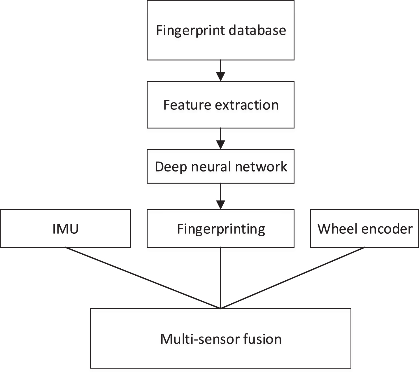
Diagram of the fusion methodology.
The mobile robot collects RSSI data at the reference point with known coordinates. Gaussian filter is firstly used to remove small probability interference items, and then Kalman filter is used to remove fluctuations caused by environmental interference. The preprocessed reference point coordinates and corresponding signal strength values are stored in the database. The fingerprint of reference point k can be denoted as [RSSk1, RSS kj . . . RSS kn , X k , Y k ].
2) Feature extraction
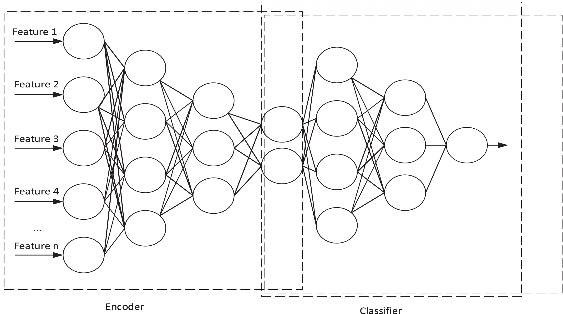
Since the read range of each reader’s antenna is limited, the RSS values stored in the fingerprint database have strong sparseness. These sparse fingerprint data lead to a decrease in the localization accuracy during the position estimation process. The method of deep autoencoder is proposed to convert the high-dimensional sparse fingerprint vector into a low-dimensional fingerprint vector by constructing a multi-layer neural network structure, so as to effectively learn nonlinear features and improve the localization performance of the model. The autoencoder framework is shown in Fig. 2.

Deep neural network framework of offline stage.
The structure of deep autoencoder is composed of two modules that is encoder and decoder. The encoder extracts the inherent characteristics of the input through training, and the output of encoder is a mapping from the input to the new feature space also knows as encoding.
Suppose the input of the whole model is h, the encoder is φ, the decoder is φ, and the output of the encoder is code, the process of the deep self-encoder can be expressed as:
The optimization goal of the deep autoencoder is that the encoder encodes the input feature, translates it through the decoder and minimizes the difference between the encoder’s input and the decoder’s output:
Where w denotes weight and b is the bias.
In order to prevent the neural network from overfitting, the influence of the neural network parameters w is added. Set the learning rate as λ, further, the optimization objective is changed to:
Suppose the neural network structure of the encoder be N layers. The number of decoder and encoder layers is the same. Let the input of the l layer be x
l
and the weight matrix be w
l
. The bias vector is b
l
, the activation function is f, and the input to the activation function is:
The output of the l
th
layer:
The training of the deep self-encoding network structure adopts the back propagation method until the desired output can be obtained from the input. The loss function of the neural network is used to estimate the degree of inconsistency between the predicted value of the model and the true value, so as to supervise the training process of the neural network in the right direction. ReLU is utilized as the activation function in the hidden layer and the activation function for the output layer is linear. The learning rate is set to 0.001 and the model is trained for 50 epochs using the Adam optimization algorithm and the mean squared error loss function.
3) Online positioning
According to the processed RF fingerprint signal data, a deep neural network is used to learn the nonlinear relationship between fingerprint features and position coordinates. In the final online positioning stage, after the RF fingerprint is collected at the point to be positioned, the RF fingerprint is fed into the deep neural network. The position coordinates of the to-be-located point can be obtained from the model. The deep neural network framework of online stage is shown in Fig. 3.
Deep neural network framework of online stage.
The structure of the deep neural network consists of two parts. The first part is a 4-layer autoencoder for noise reduction and dimensionality reduction as shown in Fig. 3. Then the four-layer multi-layer perceptron predicts the location. From the input layer to the output layer, the calculation process is:
Where w is the weight vector between two adjacent layers, b is the bias, and f is the activation function.
4) Multi-sensor fusion positioning
For the mobile robot tracking in the workshop, the Kalman filter (KF) is used to fuse the positioning information provided by the wheel encoder, the IMU, and the RFID positioning system. KF consists of two parts: prediction step and observation step.
A) prediction step:
Where x t = [p x , p y , v x , v y , a x , a y ] T is the state vector including estimated position (p x , p y ) from fingerprinting, velocity (v x , v y ) from wheel encoder and acceleration (a x , a y ) from IMU. w denotes the process noise with zero mean and covariance matrix Q.
B) Observation step:
Where H maps the state to the measurement. p denotes the measurement noise with zero mean and covariance matrix R.
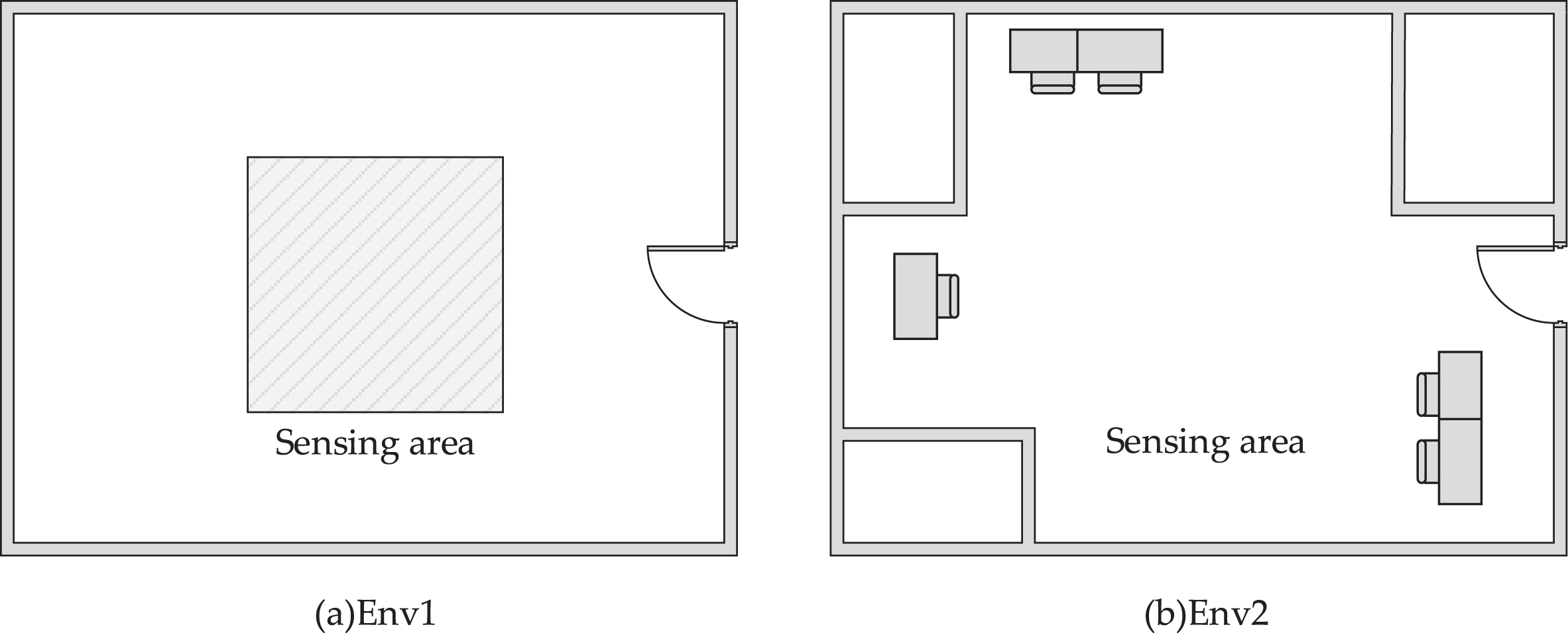
The performance of the proposed method is evaluated in this section. First, we built a low cost mobile robot with the IMU and wheel encoder sensors to collect the RSS measurements. The measurements are carried out in the research lab at our school. We deploy the Impinj R420 reader with four antennas in the corners of our lab environment, which operates in the 924.5 MHz UHF band. The Alien Technology 2x2 RFD tag is employed as reference tag, which is compatible with EPC Gen2 protocol. The layout of the research lab is shown in Fig. 5(a).

Low cost mobile robot platform.
Experiment layout of the lab.
The hardware system of the mobile robot is mainly composed of the chassis and control assembly. The motor, motor drive unit and various sensors are configured on the chassis. The control assembly includes the upper host computer and the lower machine. The hardware framework is shown in Fig. 4. The core control board of the host computer adopts the Raspberry Pi 4B, which can run the Linux system as the carrier for the deployment of the robot operating system ROS. It mainly realizes the functions of receiving and processing sensor data, multi-sensor fusion positioning, autonomous navigation and human-computer interaction. The chassis drive module controls the operation of the wheeled robot according to the mobile robot control signal issued by the host computer to realize the movement of the robot. The lower computer controller adopts the Arduino UNO development board as the main control unit. IMU, wheel encoder, motor driver, are all connected to Arduino. ESP8266 is used for the communication between the host computer and the lower computer.
Experimental results
A carton with RFID tag is placed on the mobile robot platform. In the area shown in Fig. 5, the reference point is arranged every 1 m, and the mobile robot collects the signal strength value at each reference point. There are 16 reference points. Kalman filter is used to remove the fluctuations caused by environmental interference, and finally the RSS value that can stably and truly reflect the attributes of the sampling point is collected. The fingerprints of all reference points will be collected and the fingerprint database will be built.
The trajectories of the true path, fingerprinting method and the sensor fusion method are shown in Fig. 6. The proposed method is first evaluated in the research lab which is spacious. The sensing area is not surrounded by walls. The position estimation error is calculated by:
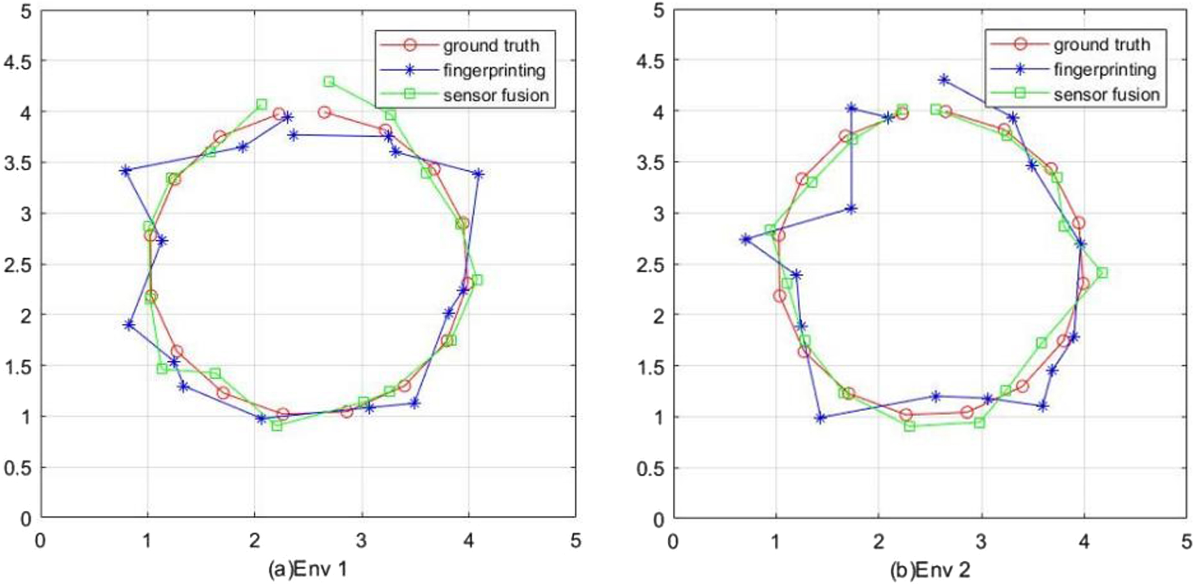
Mobile robot tracking.
Where (x′, y′) is the estimated position and (x, y) is the ground truth. Figure 7 shows the location estimation error of the fingerprinting method and the proposed fusion method in Env 1. The corresponding CDF (cumulative distribution function) are displayed in Fig. 8. The deep neural network could accurately build the relationship between the RF fingerprint and the location. Relying on the RSS signal only, the fingerprinting method could achieve the mean accuracy of 0.2537 m, and the largest position estimation error is 0.6182 m. The 50th percentile is 0.2857 m and the 90th percentile is 0.3433 m. By fusing the sensor signal from IMU and wheel encoder, the estimation error could be decreased to the mean accuracy of 0.1115 m and the largest position error is 0.1970 m. The experimental results demonstrate that the effectiveness and robustness of a single sensor are not high, but on the other hand, different sensors are complementary. Therefore, merging multiple sensors with complementary advantages is an important research direction to solve the problem of robot navigation and positioning, and multi-sensor fusion positioning is the key technology to solve the problem of mobile robot positioning.

Position estimation error of the estimated location.
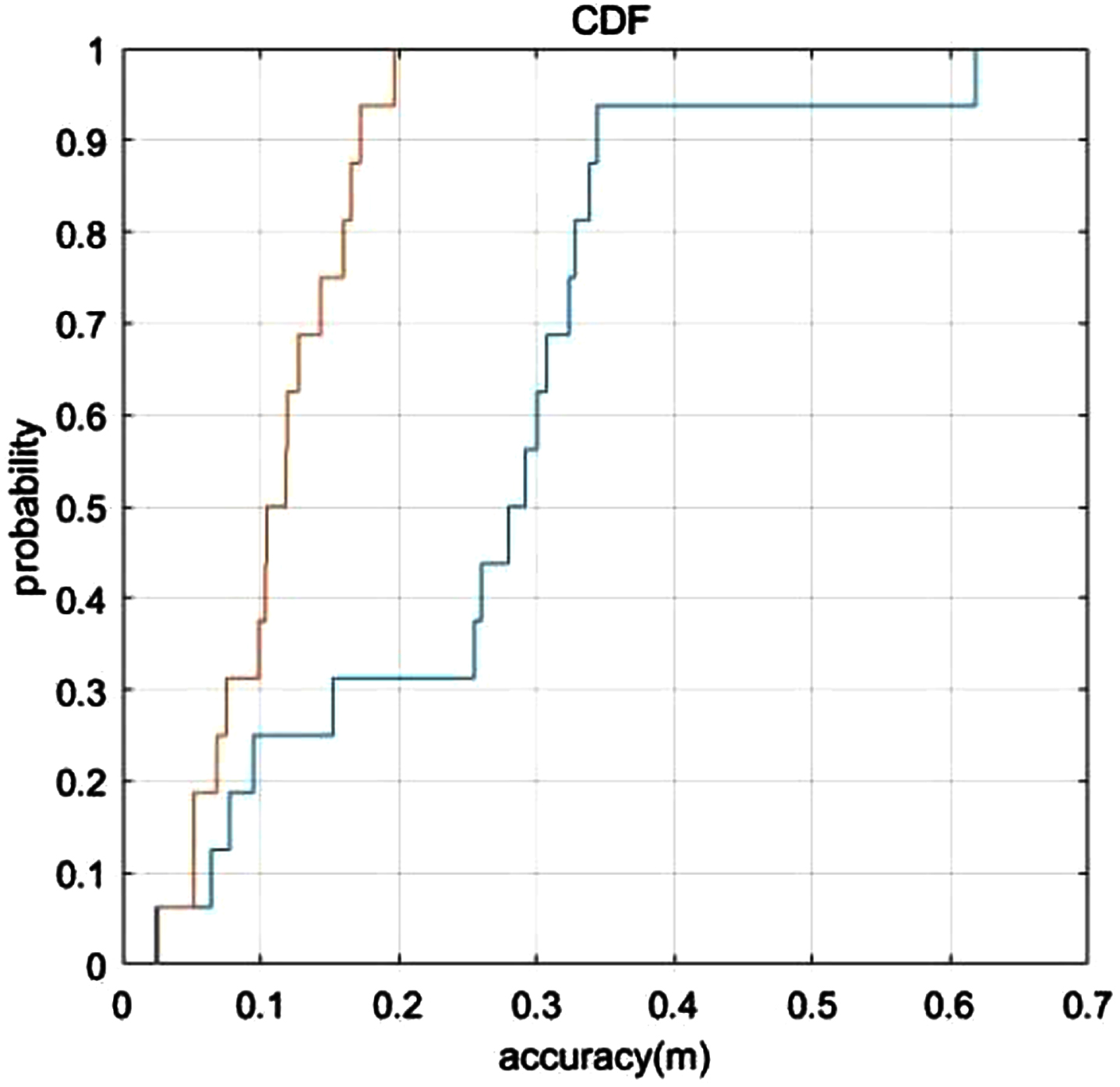
Cumulative distribution function of the localization error.
Compared to the Env1, the average estimation error of fingerprinting method increases to 0.2953 m. Since the sensing area in Envionment2 is surrounded by desks and walls, the severe multipath effect will cause fluctuations of the measured RSSI value. Even though, the proposed sensor fusion method could achieve a reasonable accuracy and the mean accuracy is reduced to 0.1151 m.
This paper presents the low cost RFID based tracking system. After the fluctuations of the RSS are removed, the fingerprint database is constructed. Deep neural network is employed to extract features from RF fingerprints and predict the position of the mobile robot. In order to realize the accurate tracking of the robot, fingerprinting is combined with the IMU and wheel encoder through kalman filter. Experimental results show that the proposed fusion method can achieve accurate tracking of the mobile robot.
In our research, deep neural network is used to establish the mapping relationship between the fingerprint and the indoor coordinates, which reduces the impact of the environment and improves the RFID localization accuracy. Kalman filter is applied to fuse IMU, odometer and RFID fingerprint positioning, the overall robustness of the system is improved, and the positioning accuracy is improved. The new method has the characteristics of high positioning accuracy, low calculation amount and strong anti-noise ability.
At present, the method for data fusion is Kalman filter which can only deal with linear system. However, in actual SLAM, the equations of motion and observation are usually nonlinear functions. In the future work, we will try Monte Carlo localization for multi-sensor fusion which performs better in nonlinear system.
Footnotes
Funding
This work is supported by Henan provincial key science and technology research project under Grant No. 232102521007.