
Abstract
Crack growth and fracture predictions are used in high temperature equipment operating in the creep and creep/fatigue range by assessing crack initiation and growth from an existing defect. These procedures are relevant to fossil, nuclear power generation, chemical and aerospace industries. There are three key factors which determine a successful methodology for remaining life assessment of engineering components. The first is good testing techniques; the second is the development of appropriate and accurate correlating parameters to treat the results in a the unified and verifiable manner in order to produce ‘benchmark’ material crack growth properties and the third is an accurate modelling procedure for life assessment methods. This presentation considers the first two aspects and identifies future trends and improvements in the developments of standardisations in creep and creep/fatigue crack growth testing. Under the auspices of the Versailles Agreement on Materials and Standards (VAMAS) committee a Code of Practice on creep crack growth of components has been developed. The procedure identifies methods of testing for non-standard, welded feature test components in VAMAS TWA31 Technical Working Area on Creep and Creep/Fatigue Crack Growth of weldments containing residual stress. The overview highlights the important points in these pre-standardisation collaborative efforts by presenting the methods of analyses and example of their application to feature type components.
Introduction
The power generation industry is striving to meet criteria for clean and sustainable energy production by increasing efficiency while simultaneously decreasing levels of chemical emissions and pollutants. The efficiency of conventional steam and gas turbine power plant can be significantly improved by increasing the operating temperature, leading to reduced fuel consumption and lower levels of harmful emissions. With the trend towards higher operating temperatures and the competing need to extend the life of existing power plant, more accurate and reliable experimental data for use in improved predictions of component lifetimes at elevated temperatures are needed.
In recent years a number of European and International collaborative programmes [1–8] have developed the testing and analysis methodologies as well as a number of databases of laboratory crack growth data base on homogenous parent material. More recently work on crack growth of weldments has been initiated under the auspices of VAMAS TWA31 to address the problems relating to specimens containing welds.
Background to VAMAS
Versailles Agreement on Materials and Standards (VAMAS) has been active in the field of standardisation of testing and analysis of elevated temperatures fracture mechanics specimens since 1987. Between 1987–1992, a new working group, TWA11, was setup to develop and formulate a standard for a high temperature test method. This involved making recommendations for measuring the creep crack growth properties of materials and using the creep fracture mechanics parameter
The main objective has been to establish accurate and reliable testing methods and a unified procedure for assessing creep crack growth at elevated temperatures in industrial specimens, which contain defects. Determination of procedures for analysing the test data using fracture mechanics concepts is important and therefore the validated correlating parameters are made available in the Code of Practice (CoP) [1]. Validation of results against measurements on standard Compact Tension C(T) laboratory specimens using ASTM E1457 has been also been carried out as it indicates the effects of constraint on specimen geometry and size. There are a number of parameters such as K, linear elastic fracture mechanics,
VAMAS TWA31 objectives
In the past it has been shown that a collaborative effort to identify methods in testing and analysis at high temperatures has succeeded in developing standards and codes which has in turn has assisted in improving life assessment methods [1]. This programme will be extended to weldments containing extreme inhomogeneity in their material properties under VAMAS TWA31. The principal objectives of the TWA31 collaboration committee set up in September 2005 is to consider the ‘Creep/fatigue testing of weldments containing residual stress’ will be:
Undertake a review of the information available on the type material, methods of welding, and crack growth data of weldment specimens and welded components at high temperatures.
Initiate a Round Robin testing programme of testing welded specimens within the TWA31 collaboration based on the available information from the review. The Round Robin will cover four different steels namely (347 stainless steel weld, 316H stainless steel, P22, P91 and P92) steels which have been offered for testing by partners in UK, Germany and Japan, and Korea.
Finite Element modelling of residual stresses and identification of the role of stress relaxation during the testing of the component at elevated temperatures.
Measurement of residual stresses in Compact Tension specimens from the Round Robin crack growth tests before and after crack initiation using neutron and X-ray diffraction.
Identify the appropriate fracture mechanics parameters and materials and weld conditions for different geometries, to cover the majority of cases for testing of weldments.
Based on the results of the research provide recommendations on weldment testing and analysis plus the effects of stress relaxation at high temperatures.
The new programme will build on the findings from previous work [1–7]. Described below is a short description of the different industrial life assessment procedures and methods for analysing data from different geometries and feature components which can subsequently be used in predictive lifing methods.
Background to life assessment codes
Components in the power generation and petrochemical industry operating at high temperatures are almost invariably submitted to static and/or combined cycle loading. The alloys used can vary between low carbon steels to high chrome superalloys with various alloying contents. In addition these components have welded parts which will have different alloying and microstructural properties. The failures can be due to large deformations, creep rupture and/or crack growth. The development of codes in different countries has moved in very similar direction and in many cases the methodology has been borrowed from a previously available code in another country. Early approaches to high temperature life assessment have used methodologies based on defect-free assessment codes. For example ASME Code Case N-47 [17] and the French RCC-MR [18], which have many similarities, are based on lifetime assessment of un-cracked structures. More recent methods make life assessments based on the presence of defects in the component. The more advanced codes dealing with defects over the range of creep and creep/fatigue interaction in initiation and growth of defects are the BS7910 [19], British R5/R6 [20,21], the API RP 579 [22] and the French A16 [23] which have clear similarities in terms of methodology. It is also obvious from these assessment methods that the correct evaluation of the relevant fracture mechanics parameters, for which the lifetime prediction times are dependent upon, are extremely important.
It is also evident therefore that the detailed calculation steps, which are proposed in these documents alone, do not improve the accuracy of the life prediction results. In any event as these procedures have been validated for limited sets of geometries and ‘Benchmark’ material data, their use in other operating conditions will need careful judgment. These aspects have been considered in VAMAS TWA25 in order to produce validated fracture mechanics parameters form different geometries for this purpose. The procedure highlights recommendations for improved test methods so that verifiable material properties are collected. This allows the modelling methods using standard laboratory and feature component data to be used with increased confidence in life estimation codes. This pre-standardisation work is of relevance to ASTM, ISO, ASME, API (American Petroleum Institute) and PVRC (Pressure Vessels Research Council (USA)) as well as to allow further improvements to life assessment CoP such as R5, BS7910 and A16. Clearly the recommendations resulting from this CoP will be useful for increasing confidence in defect assessment codes. In addition the similarities of the approaches in the various codes do not necessarily imply that calculations by the different methods will give the same predictions. It may be possible that under certain controlled and validated circumstance the predictions can be optimised. It is clear that a critical comparison is only possible when the same method is used on another material and condition or the same test cases are examined by the different codes.
Parameters for analysing high temperature cracking
Typically, fracture mechanics concepts are used to characterise crack initiation and growth at high temperatures. Usually at short times the stress intensity factor K, or the elastic–plastic parameter J, is employed to describe the stress and strain distributions at a crack tip whereas at long times, when steady state conditions have been reached, the creep fracture mechanics term
Steady state CCG analysis
Creep crack growth rate under steady state for a creep ductile material is usually analysed using the fracture mechanics parameter
Where creep dominates most often the constants in Eq. (1) are obtained from tests that are carried out on compact tension (C(T)) specimens based on the recommendations of ASTM E1457 [8] standard and hence,
The data obtained from C(T) specimens using Eq. (1) is considered as ‘benchmark’ material data for creep crack growth properties of the materials in the same way as creep strain rate and rupture for uniaxial creep tests. These data can be employed directly in crack initiation and growth models described in the different codes [19–23] to estimate residual lives in components. For components such as pipes and plates, on the other hand,
When a structure containing a defect is first loaded the stress distribution is given by the elastic K-field or the elastic–plastic J-field. Therefore, time is required for the stresses to redistribute to the steady-state creep stress distribution controlled by
From Eq. (1) it may be expected that the time,
For fatigue crack growth it is assumed that the mechanism is time and temperature independent and K or J dominates at the crack tip. At room temperature under cyclic loading conditions, crack propagation usually occurs by a fatigue mechanism where the Paris Law can describe crack growth/cycle
At elevated temperatures combined creep and fatigue crack growth may take place. However in most cases fatigue dominates at higher frequencies (
Total crack growth per cycle,
Specimen names and abbreviations
Specimen names and abbreviations
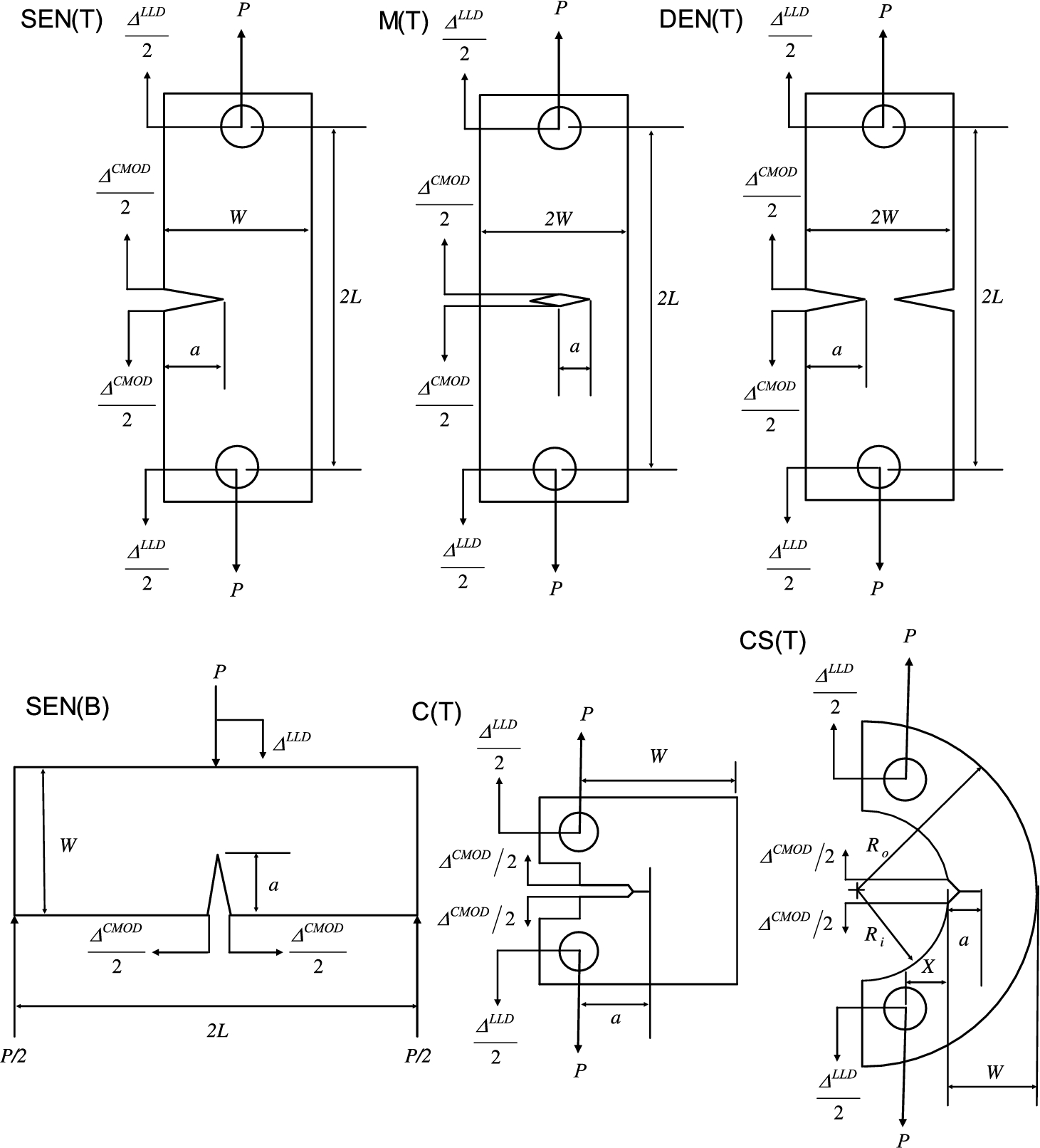
Schematic drawings for the fracture mechanics geometries showing the loading directions, and the load-line
As a result of EU collaborative programmes [2–7] especially in HIDA [3], LICON [4] and CRETE [5] tests were performed on a number of fracture mechanics geometries. The VAMAS procedure [1] uses the information provided by these programmes to identify and catalogue six specimen geometries, as given in Table 1, that have been verified for the purpose of creep and creep/fatigue crack growth and initiation testing and are comparable to C(T) test data [26]. Abbreviations denoting the specimen geometries are also given in Table 1. The choice of specific specimens does not mean that other geometries should not be used for testing but that they would need validation before their inclusion in the procedure. Detailed dimensions, machining instructions methods of setting up and limits of testing accuracies are described in the procedure. Figure 1 shows the schematic drawings of the six fracture mechanics geometries showing the loading directions, and the load-line

(a) Example of normalised crack length versus time data and (b) comparison of the creep crack growth rates with
An example of data obtained and analysed from these specimens are shown in Fig. 2. Figure 2(a) shows the normalised crack length versus time for the different geometries and Fig. 2(b) shows the correlation of the data when compared to a C(T) databand of the same 316 type stainless steel material. This suggests that for the range of sizes and geometries used the crack growth data obtained is comparable to within the inherent scatter of data.
Feature type specimens, which can represent component related geometries, were also tested for verification and validation in different collaborative programme [3]. A schematic of these types of specimens are shown in Fig. 3. These consist of pipes, plates and notched bar cracked specimens. The testing of such specimens is costly and difficult and is not recommended as a routine procedure for deriving data but they can be used to validate the laboratory data in comparison to components.
Analysis of component or feature component testing was an important part of VAMAS TWA25 procedure [1]. It has been shown previously that although different codes employ Eqs (5)–(7), often different formulae are used to evaluate K and

Feature geometries showing a pipe, pipe-bend notched bar with circumferential crack and plate under bending and tension feature specimens showing crack and loading positions [1]. (Colors are visible in the online version of the article;
Furthermore since it has been shown [31] that there is no absolute correct solution for reference stress in components and that in order to get an overall agreed definition compromises have to be made. It may be possible by using detailed FE analysis of the geometry in 3D and the right boundary conditions and material properties to improve the solutions in the future. But for the present it is more important to be able to compare inter-laboratory data and reach definitive comparison with the results. Hence the recommendations in the CoP [1] of specific formulae for evaluating the
For plates there exist several reference stress solutions [19–23] which use Eqs (4), (6) to derive

Figure 4 gives and example of comparing the effects of frequency and the plate geometry for a 316LN type stainless steel tested at 650°C [3]. Figure 4(a) highlights that for low frequencies the crack growth data for this steels lies within the scatter of the static load data, suggesting that the cracking is time dependent and due to creep at low frequencies. Figure 4(b) compared the same databand with data from plate tests. In this case there is a clear difference between negative R-ratios and the rest of the cyclic test data of the plate lying at the upper and lower bounds of the C(T) databand respectively. This suggests that caution would be needed in using standard laboratory tests to predict component behaviour where negative R-ratios are present. It is clear therefore that a comprehensive validation of different materials, geometries and loading conditions would be needed to validate the procedure fully.
In the same way as the plates Eqs (4), (6) are used to derive

(a) Comparison of welded and parent crack growth rate for P22 steel tested at 565°C, and (b) comparison of crack growth versus
Figure 5 gives an example of comparison of crack growth analysis of the C(T) and pipes geometries in both parent and weld P22 steel tested at 565°C. Figure 5(a) shows little difference between parent and heat affected zone (HAZ) region tests for the C(T) P22 specimens. On the other hand Fig. 5(b), for the pipe test whilst not showing a noticeable difference between parent and HAZ cracking it does show an effect due to geometry when compared with the databand of Fig. 5(a). This could be due to constraint as well as the fact that derivation of data from pipe test are much more difficult than for standard C(T) specimen [8,31]. This highlights the fact that more tests would be needed to improve the validation of laboratory data with component data.
In creep and creep/fracture testing an important qualitative measure of the experiment is pre- and post-metallurgical examination of the fracture. It is well known that creep is a time-dependent phenomenon in which voids grow and coalesce at the grain boundaries to produce a crack. Also fatigue is only cycle dependent and failure is transgranular. Figure 6(a) shows an example of creep crack growth failure at static loading in a C(T) specimen. The crack front is relatively straight and the features show intergranular failure.
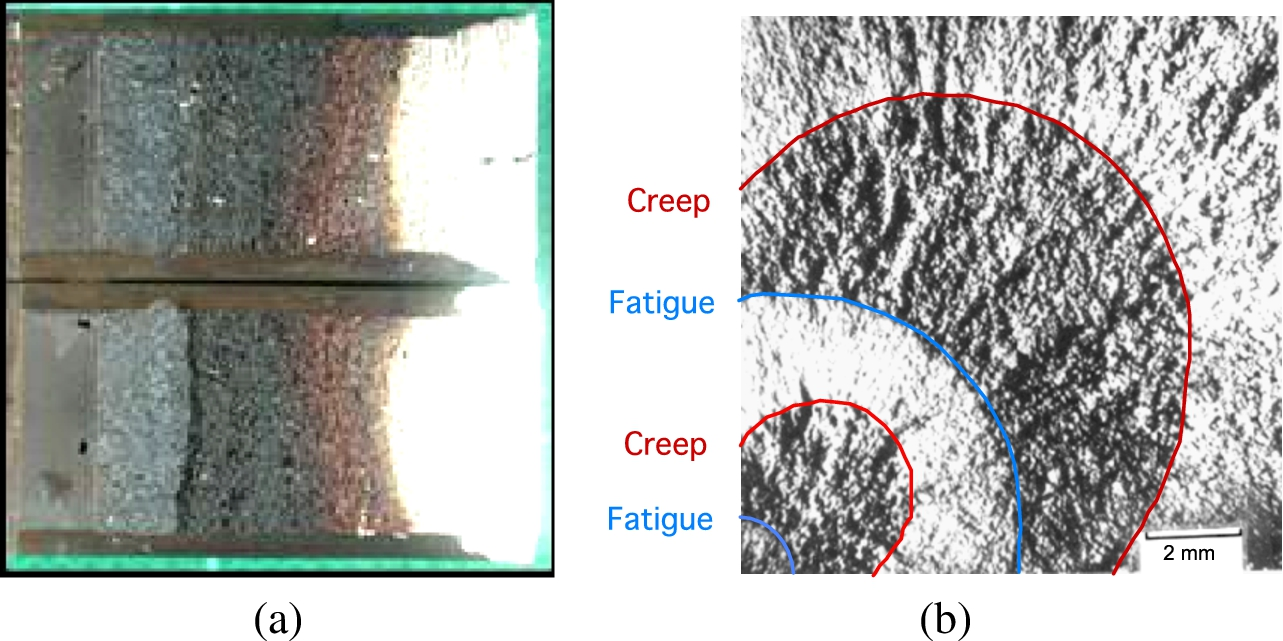
Fractograph features of (a) a compact tension C(T) 316H stainless steel specimen tested at 550°C at fixed load, and (b) a corner crack tension specimen in which loading has been changed between static creep to cyclic 10 Hz fatigue to highlight the crack from between the two fracture mechanisms. (Colors are visible in the online version of the article;
Figure 6(b) shows a rectangular tensile specimen containing a corner crack. It is seen that when the loading is changed from cyclic fatigue at 10 Hz to static creep and reverse the crack front shape changes. This is an indication of the effects stress state in creep in which cracking more likely tends to occur in plane strain that under plane stress. Constraint effects in creep, therefore, will have a profound effect on cracking behaviour [11].

Fractography of the fracture surfaces of a corner crack tension specimens from an AP1 superalloy at 700°C over a range of frequencies showing transition between (a) full transgranular to (d) fully intergranular creep fracture with (b) at 0.1 Hz and (c) at 0.01 Hz being in the intermediate stages where creep/fatigue interactions occurs [29]. (Colors are visible in the online version of the article;
Figure 7 gives a further indication of the mode of fracture and creep/fatigue interaction under static and cyclic loading. It is important to note that the linear cumulative damage in Eq. (11) is qualitatively verified from these fractographs in which at the intermediate frequencies of 0.1 and 0.01 Hz facets of intergranular and transgranular fracture are clearly visible in proportion to their creep and fatigue components.

Example of crack growth though the HAZ in a P22 pipe feature component [3]. (Colors are visible in the online version of the article;
Figure 8 shows an example of a crack in a feature test weldment for P22 the data for which are analysed in Fig. 5(b). Clearly there are important issues such as the effects of residual stress that are attached to the methods for testing and the analysis of such tests in which crack path is also likely to deviate and make the results more complex. The new initiative VAMAS TWA31 plans to deal with these problems under the title ‘Creep crack growth in weldments containing residual stresses’. The pre-standardisation analysis will produce future recommendation on the testing and analysis for weldments to be included in the present VAMAS procedure [1].
Creep and fatigue crack growth models as well as residual defect assessment codes need reliable and verifiable material properties data and validated fracture mechanics parameters for use in their predictive methodologies. VAMAS committee has incorporated the results from the research in a number of EU collaborative projects [2–6] to develop an overall methodology for deriving acceptable data and validated parameters for life assessment analysis. The results are also compatible with ASTM E1457 [8] standard for testing C(T) specimens. In addition the newly developed ASTM E2670 [33] on creep/fatigue crack growth testing identifies the problems associated with creep/fatigue interaction and presents an analysis method for a range of frequencies.
Footnotes
Acknowledgements
The author acknowledges the support of EDF Energy and VAMAS and collaboration of partner institutions in HIDA, LICON and CRETE (European Collaborative programmes (1996–2004) in addition to the partners in VAMAS TWA25, VAMAS TWA31 and ASTM E08 Committees.