
Abstract
Non-linear fracture analysis of the Double Cantilever Beam (DCB) specimen is performed by using the J-integral approach. For this purpose, methods of Mechanics of materials are applied. Closed form analytical solutions of the J-integral are obtained by using two non-linear beam models (ideally elastic–plastic model and model with linear hardening). It is assumed that the material has the same properties in tension and compression. The fracture behaviour is analyzed at each typical stress level in the DCB in the process of increasing of the external load. The influence of the material non-linearity on the fracture behaviour is discussed. The effect of slope of the stress–strain curve in the portion with linear hardening on the fracture behaviour is evaluated. The analysis revealed that the J-integral value increases when the slope increases. The analytical approach developed in the present paper is very useful for parametric analyses, since the simple formulae derived capture the fundamentals of non-linear fracture in the DCB configuration.
Introduction
Due to their superior specific strength and stiffness, fibre reinforced composite laminates are ideal for weight critical structures. With increasing use of laminates in load-bearing structural components, the need to understand and predict the failure behaviour of these materials has also increased.
Delamination, i.e. the separation of the layers in laminated materials, is the most severe type of damage which reduces considerably the strength and the stiffness of the structure and may, in some cases, lead to complete failure [1,2]. The most common causes of delamination are defects induced in a result of careless manufacturing. Similar defects may also arise during lifetime of the laminated structure due to low-velocity impact events, cyclic loading, thermo-mechanical loads, and in-service incidents such as tool drops or careless handling during maintenance. Delamination cracks may be very difficult to detect since they are often embedded within the structure, which makes them especially insidious. Therefore, the delamination fracture mechanisms should be carefully considered in evaluation of laminated structures for durability and damage tolerance.
The literature on the delamination problem is wide [3–19]. Usually specimens of beam type are used for characterization of delamination fracture behavior of laminated composite structures (one of the most commonly used configurations is the Double Cantilever Beam (DCB) specimen). The delamination is studied in terms of the strain energy release rate by applying the concepts of linear-elastic fracture mechanics. For this purpose, various analytical solutions are obtained using the linear-elastic beam theory. The basic assumption of these solutions is that the relationship between the stresses and strains can be expressed by the Hook’s law. However, in the cases of composites with high fracture toughness, the applicability of linear-elastic fracture mechanics is limited, because the plastic deformation usually begins prior to onset of macroscopic crack growth from the initial crack tip position. In such cases, the fracture analysis should take into account the material non-linearity.
The objective of the present paper is to perform a non-linear fracture analysis of DCB specimen. The integration path independent J-integral is used as a fracture characterizing parameter. Two non-linear stress–strain curves are considered in the analysis. Closed form analytical solutions of J-integral are obtained using a model which is based on Mechanics of materials. Effects of stress–strain curves parameters on non-linear fracture are evaluated.

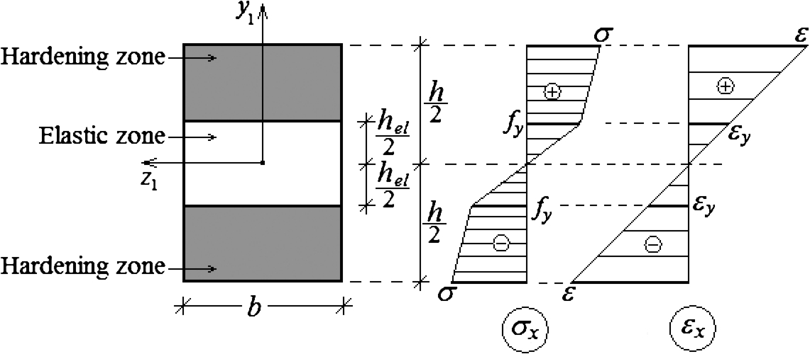
The DCB configuration.
The DCB configuration analyzed in the present paper is illustrated schematically in Fig. 1. There is a crack in the mid-plane of the beam. The external load consists of two moments applied at the free end of the crack arms. The fracture behavior is analyzed by using the J-integral approach. The J-integral is written as [20]
The J-integral is invariant with respect to the integration contour [20]. Therefore, we decide the integration contour, Γ, to coincide with the beam contour as shown in Fig. 1. In this way, the J-integral solution is substantially facilitated. For instance, the J-integral value is non-zero only in segments A and B of the contour (Fig. 1). Due to the symmetry conditions, it is enough to solve the J-integral in segment A and to double the result obtained.
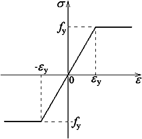
Stress–strain curve of an elastic–perfectly plastic material.
We assume that the mechanical response of the beam can be described by the ideally elastic–plastic diagram for both tension and compression (Fig. 2). When the external load magnitude is relatively low, the beam deforms in linear-elastic stage, i.e. the Hook’s law is valid. In this case, for the components of the J-integral in segment A (Fig. 1), we have
The partial derivative,
By substitution of (2), (3) and (4) in (1), we obtain
It is known that at linear-elastic behaviour of the material, the J-integral value coincides with the strain energy release rate. This fact is used here to verify solution (5). Indeed, (5) coincides with the expression for the strain energy release rate in DCB [21].
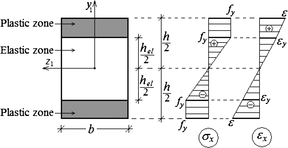
Plastic zones and diagrams of normal stresses and linear strains in the crack arms.
The crack growth will begin when
However, if the fracture toughness is high, the plastic deformation will begin prior to the onset of crack growth. When the moment gradually increases, plastic deformation first will begin in the remotest edges of the crack arms, where the normal stress will attain the yield stress limit,
If
The normal stresses in the elastic zone are distributed linearly
The partial derivative,
The strain energy density is found as
The J-integral in the plastic zones of the crack arm cross-section is written as
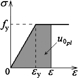
Strain energy density in the plastic zones of the crack arms.
The normal stresses in the plastic zones are equal to the yield stress limit, i.e.
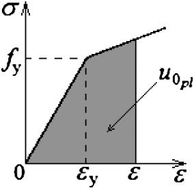
The strain energy density in the plastic zones of the crack arm cross-section is equal to the area enclosed by the stress–strain curve [23–26] (Fig. 4):
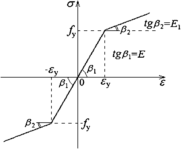
Stress–strain curve with linear hardening.
We analyze the fracture behaviour of the DCB configuration using a stress–strain curve with linear hardening (Fig. 5). At low magnitudes of the external moments, the J-integral solution is expressed by formula (5).
Plastic zones and diagrams of normal stresses and linear strains in crack arms.
If
It should be mentioned that at
We replace
The strain energy density is found as
Strain energy density in the plastic zones of the crack arms in stage of hardening.
In the plastic zones of the crack arm cross-section, the J-integral is expressed by (20). The normal stresses in the plastic zones are obtained as (Fig. 5)
The strain energy density in the plastic zones of the crack arm cross-section is equal to the area enclosed by the stress–strain curve [23–26] (Fig. 7), i.e.

The J-integral value plotted against the proportion,
It should be mentioned that at
The influence of the stress–strain curve slope in the portion with hardening on the non-linear fracture behaviour is analyzed. For this purpose, the J-integral is calculated by formula (49) at different values of the proportion,
Non-linear fracture in the DCB configuration is studied theoretically using two models (ideally elastic–plastic model and model with linear hardening) which are based on the Mechanics of materials. The fracture analysis is carried-out using the J-integral approach. The integration contour is chosen to coincide with the beam contour in order to facilitate obtaining of the J-integral closed form analytical solutions. The influence of the slope of the stress–strain curve in the portion of linear hardening on the non-linear fracture is also analyzed. It is found that the increase of the slope leads to increase of the J-integral value. The J-integral solutions obtained in the present article can be applied to calculate the critical J-integral value with taking into account the material non-linearity using experimentally determined critical load at the onset of crack growth from the initial crack tip position in the DCB specimen. The analytical approach applied in the present study is very useful for parametric analyses, since it captures with simple formulae the fundamental non-linear fracture behaviour of the DCB configuration.