
Abstract
Introduction
The centrifugal compressor is the core equipment of gas deliveries used in energy, petroleum, chemical, and other important industries. High cycle fatigue (HCF) and very high cycle fatigue (VHCF) induced by wake flow and other causes are the main failure modes of impellers which are the key component of centrifugal compressors. Research on the fatigue behavior and mechanism of impeller material in the VHCF regime is beneficial to fatigue design and the remanufacturing of impellers, and it also has important significance to ensure a long operation life of centrifugal compressors.
According to the number of load cycles up to failure, there are three types of fatigue: low, high and very high cycle fatigue. Cracks usually initiate from the surface in low and high cycle regimes, and from the subsurface in the VHCF regime. In the adjacent region of high and very high cycle fatigue, a few cracks in the HCF regime may initiate from the subsurface and a few cracks in the VHCF regime may initiate from surface. The fish-eye is the typical fracture of VHCF [1–5]. VHCF is very different from low and high cycle fatigues. “Hydrogen embrittlement” [6] and “dispersive decohesion of spherical carbide” [7] are the two main theories of VHCF. Since hydrogen surrounding an inclusion was observed [8] by Hydrogen Isotope X-ray Imaging and Secondary Ion Mass Spectroscopy, hydrogen has been widely accepted as having an important role in the VHCF regime. Ultrasonic fatigue testing with very high loading frequency (20 kHz) has become an important method of VHCF research, although there are some disadvantages in this method such as frequency effect and specimen temperature rise.
Chemical composition of FV520B wt%
Chemical composition of FV520B wt%
Mechanical properties of FV520B-I and FV520B-S
Experimental material
FV520B is a type of martensitic precipitated hardening stainless steel with good comprehensive properties. Its main chemical components are shown in Table 1. The density of FV520B-I plate is
Experimental method
Fatigue tests were conducted on a Shimadzu USF-2000 at a resonance frequency of 20 kHz and room temperature in air ambient. The resonance interval was 500 ms per 500 ms (i.e. the machine stops for 500 ms when it has operated for 500 ms), and stress ratio
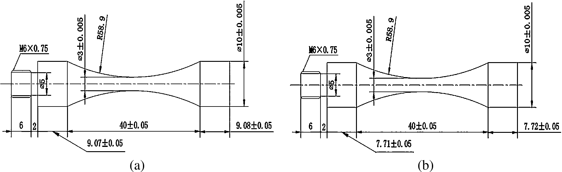
Specimen geometry and dimensions (in mm). (a) FV520B-I. (b) FV520B-S.
Microstructure
The cross-section microstructure of specimens etched by a solution of picral and hydrochloric acid are shown in Fig. 2. Figure 2(a) shows the microstructure of FV520B-I. It can be seen that many white ferrites are distributed in the tempered sorbites. The granular carbides and some small inclusions are observed as distributed within the matrix. Figure 2(b) shows the microstructure of FV520B-S, which is similar to the tempered sorbites.
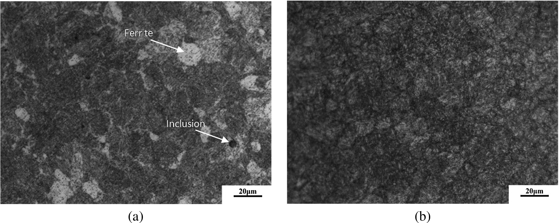
Microstructure observations of FV520B. (a) FV520B-I. (b) FV520B-S.

The S–N curves of FV520B.
Involving the test results of FV520B-I what we obtained before [9] and the S–N curves of FV520B are shown in Fig. 3. For FV520B-I, the test data before 107 cycles and that after 107 cycles are very different. The S–N curve consists of two different sloping lines which were obtained by fitting relevant data via the least squares principle. The S–N curve before 107 cycles is relatively flatter than that after 107 cycles, and the specimen is considered to have no fatigue limit up to 109 cycles. The specimen usually fractures on the surface in a short fatigue life regime while it usually fractures in the subsurface in a VHCF regime. The cracks initiated from the surface or subsurface near the turning point of the S–N curve, and one crack initiated from the surface when the fatigue life was close to 108 cycles. So there was a competition between the surface initiation and the subsurface initiation. For FV520B-S, it can be seen that the S–N curve is composed of the inclined line and the horizontal line, and the specimen always fractured on the surface. When low amplitude stress was applied to the specimen, it did not rupture even up to 109 cycles, so it is considered that the FV520B-S has a conventional fatigue limit. The S–N curve of FV520B-S is far below FV520B-I’s, and the gap between the two S–N curves is up to 200 MPa in the low and high cycle regimes. The two S–N curves gradually become closer to each other as the S–N curve of FV520B-I continuously declines in the VHCF regime.
Fracture surface observation
Some tests were terminated early because the specimen with a surface crack was beyond the resonance condition when the fatigue life was low. In this situation, the specimen became hard to break as the crack insufficiently propagated although it was cooled in liquid nitrogen. This phenomenon appeared in some FV520B-I and all FV520B-S specimens with a surface crack. So, the fracture surfaces of specimen which could be broken were observed by a Scanning Electron Microscope (SEM).
When the fatigue life was less than 107 cycles, cracks in most specimens of FV520B-I and all specimens of FV520B-S initiated from the surface. In this case, the crack initiation site appeared flat and smooth, and some fatigue trench lines radiated outward. The propagation region of the crack looked like an oval leaf and secondary cracks were found in this region as shown in Fig. 4. One crack initiated from the subsurface inhomogeneous microstructure in a FV520B-I specimen, and the fish-eye which is the typical feature in the VHCF regime appeared as shown in Fig. 5. The energy spectrum analysis result of crack initiation site is shown in Fig. 6.
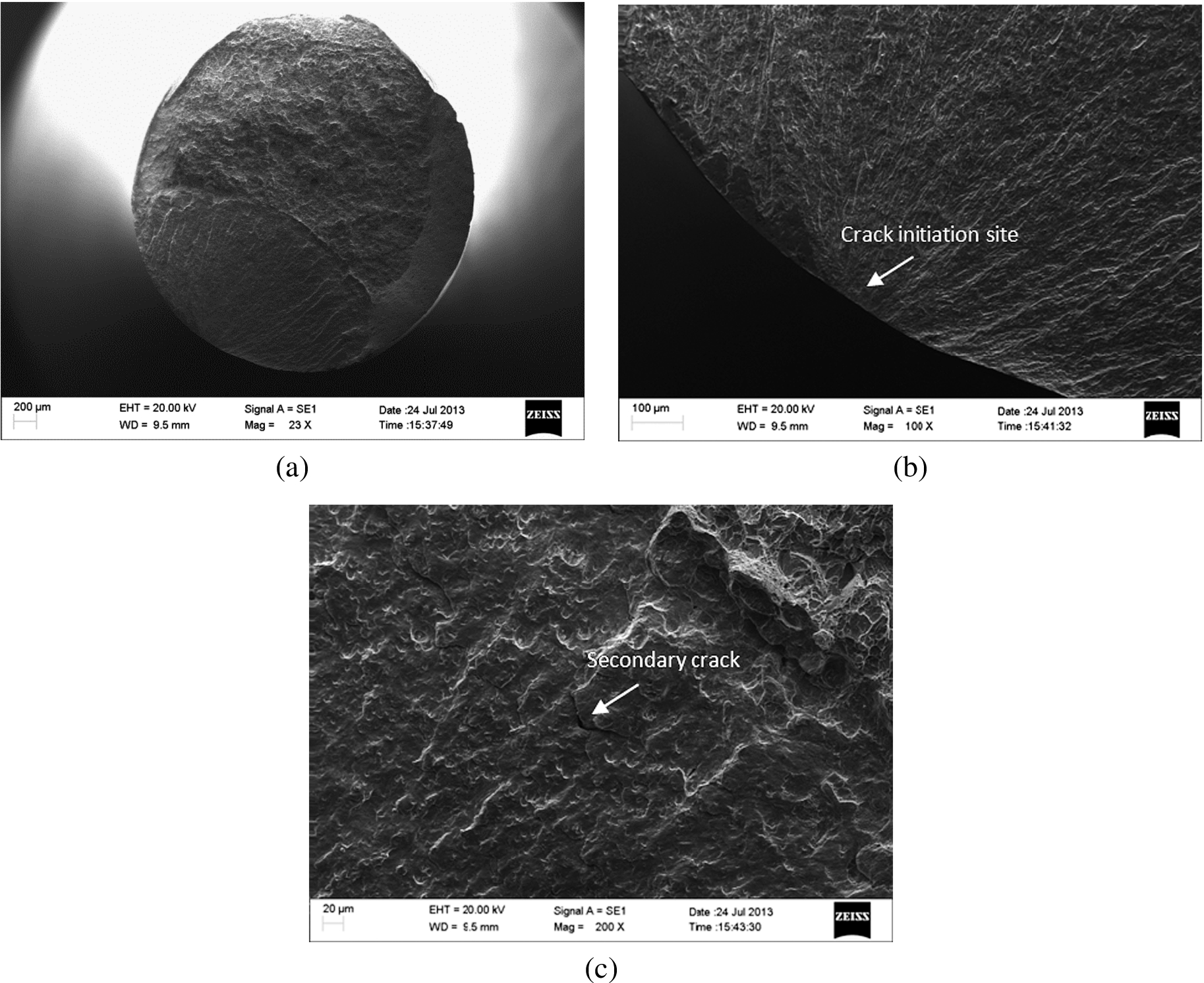
FV520B-I high cycle fatigue crack initiation from surface (
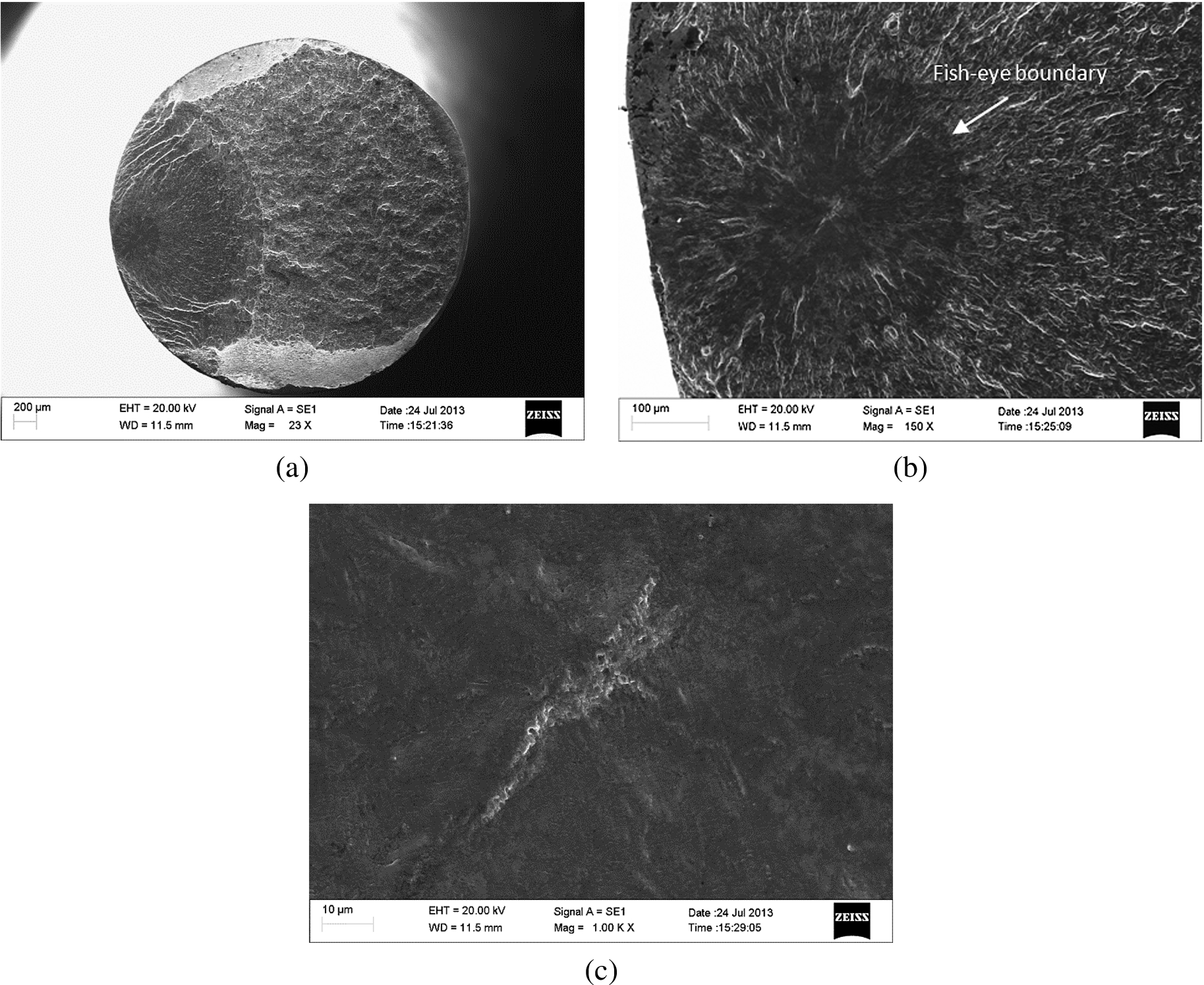
FV520B-I high cycle fatigue crack initiation from the subsurface matrix (

The energy spectrum analysis result of crack initiation site (
Only the FV520B-I specimen fractured when the fatigue life was higher than 107 cycles. The authors had known that most cracks initiated from the subsurface inclusions in the VHCF regime and one crack initiated from the surface when the fatigue life was close to 108 cycles [9]. And the authors further found two cracks initiation from the subsurface matrix. The initiation modes of FV520B-I cracks in the VHCF regime are shown in Fig. 7. The inclusions of the crack initiation sites were identified as Al2O3 by energy spectrum analysis. And the energy spectrum analysis results of crack initiation sites of relevant specimens are shown in Fig. 8.
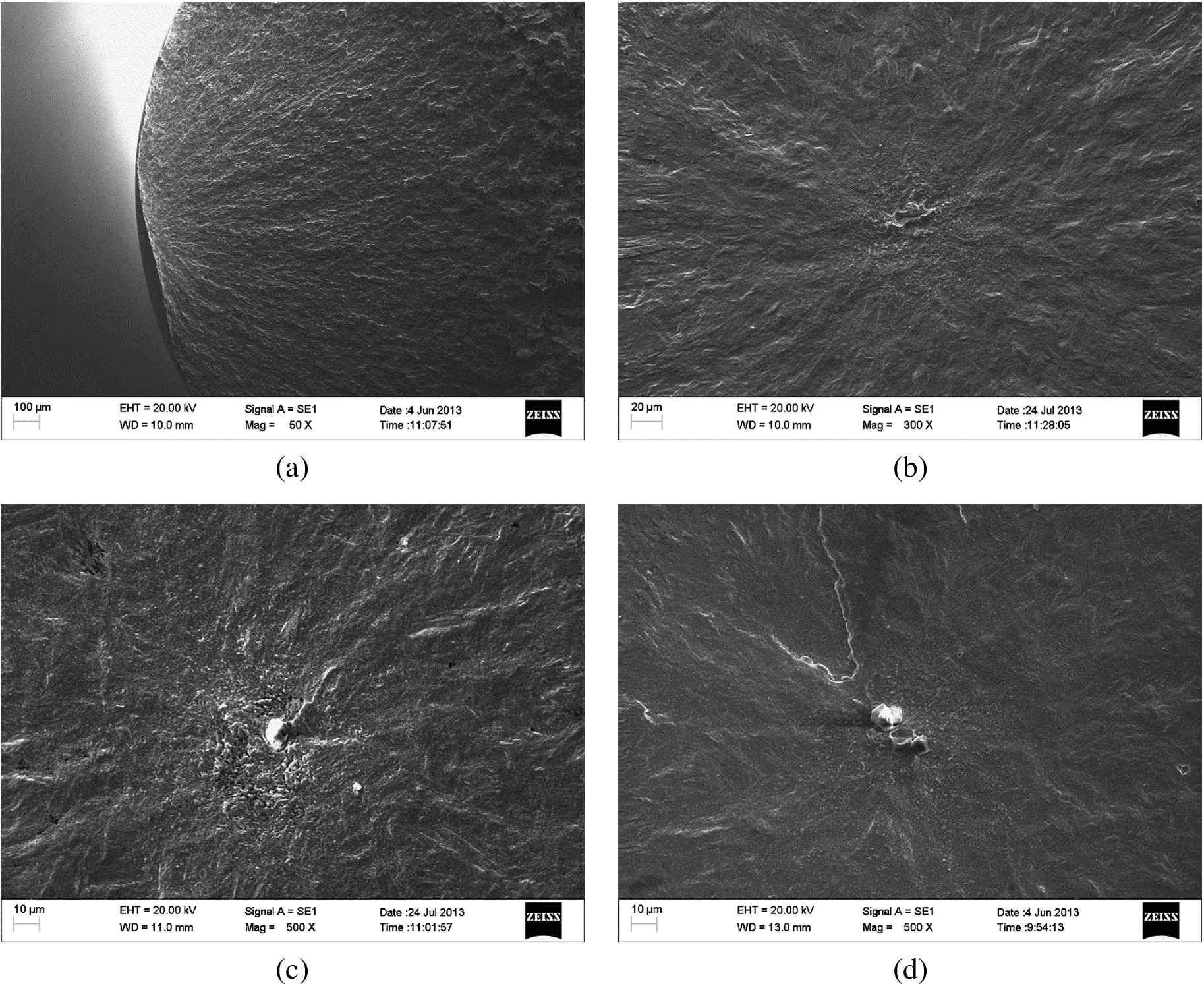
Initiation modes of FV520B-I cracks in the VHCF regime. (a) Initiation from surface (
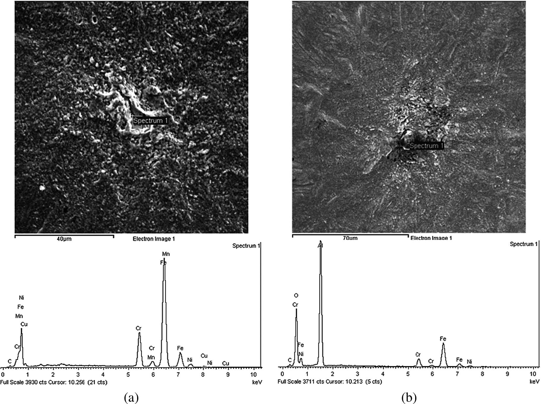
The energy spectrum analysis results of crack initiation sites. (a)
The difference of the subsurface crack initiation sites. (a) Initiation from subsurface inclusion (
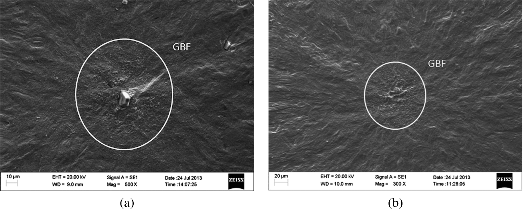
A highlight area (granular bright facet, GBF) around the inclusion seemed relatively rough and different from the flat and smooth region of the usual crack initiation site. This highlight area also appeared when the crack initiated from the subsurface matrix, as shown in Fig. 9.
Characteristic area sizes of the fractures
Characteristic area sizes of the fractures
Effects of heat treatments on S–N curve characteristics and crack initiation modes
The difference of heat treatments has an obvious significance on the microstructure and the mechanical properties of FV520B as shown in Fig. 2 and Table 2. FV520B-I is tempered at lower temperature 470 ± 10°C and thus obtained a higher strength level 1170 MPa, while FV520B-S is ageing at higher temperature 625–640°C and thus obtained a lower strength level 916 MPa. The strength level usually affects the S–N curve characteristics as follows: for low-strength steels, the S–N curve has a horizontal asymptote shape and clearly has a fatigue limit, and for high-strength steels, the S–N curve has step-wise curves of duplex curves or a continuously descending curve [10]. As show in Fig. 3, the S–N curve of FV520B-S resembles the case of low-strength steels, and only the surface fatigue failure mode exists and the plateau corresponds to the surface fatigue limit. The S–N curve of FV520B-I resembles the case of high-strength steels, and it continuously descends. The two sloping lines correspond to the surface fatigue failure mode which occurs in the short fatigue life regime and the subsurface fatigue failure mode which occurs in the VHCF regime. When the stress amplitude is 675 MPa, the scatter of fatigue life is evident, similar to the plateau when the probability of surface crack initiation is equal to subsurface crack initiation. Meanwhile, fatigue resistance usually increases with an increase of tensile strength (or Vickers hardness) [11], so the S–N curve of FV520B-S is far below FV520B-I’s because of the strength difference between FV520B-I and FV520B-S.
Figure 7(c), (d) shows that the subsurface cracks of FV520B-I initiated from the interface of the matrix-inclusion due to debonding, but no cracks appeared in the inclusions. This phenomenon was in accordance with the usual initiation mode of subsurface cracks in high strength steel mentioned by Tanaka et al. [12]. Previous studies demonstrated that the cracks in the VHCF regime of some materials could initiate from the subsurface matrix [13,14]. And in our research one crack initiated from the subsurface matrix in the HCF regime and two cracks initiated from the subsurface matrix in the VHCF regime for FV520B-I as shown in Fig. 5(c) and Fig. 7(b). Since soft ferrites are distributed in the matrix of FV520B-I as shown in Fig. 2(a) for lower temperature tempering, and soft ferrites can easily generate a stress concentration and develop into crack initiation sites under the action of cycle stress. Relevant mechanism that subsurface cracks initiate from a weak microstructure has been proved too [13,15]. So the soft ferrites may be the cause of FV520B-I cracks initiation from the subsurface matrix.
After the cracks initiated from the interface of the matrix-inclusion or the subsurface matrix, the cracks slowly propagated and formed the GBF which appeared to be the major characteristic of the VHCF fracture as shown in Fig. 9. There are different views about the formation of the GBF [6,7], and most scholars generally think that the existence of hydrogen is an important cause of GBF formation [8]. The GBF did not appear when the crack initiated from subsurface matrix under the higher amplitude stress as shown in Fig. 5(c). The authors regard that the stress intensity factor of crack initiation from subsurface matrix caused by higher amplitude stress was larger than the threshold value of stress intensity factor, so the propagation of crack was not need the acceleration of hydrogen and the GBF did not appear. On the contrary, the stress intensity factor of crack initiation from subsurface matrix was smaller than the threshold value of stress intensity factor under the lower amplitude stress, and the GBF appeared for the propagation of crack needed the acceleration of hydrogen as shown in Fig. 9(b).
The relationships of fatigue life in the VHCF regime of FV520B-I with characteristic area sizes
The relationships of fatigue life in the VHCF regime of FV520B-I with characteristic area sizes are shown in Fig. 10. The characteristic area sizes mainly include the inclusion diameter, GBF diameter, fish-eye diameter, and distance from the crack initiation site to the specimen surface.

Relationships of fatigue life in VHCF regime of FV520B-I with the characteristic area sizes. (a) Relationship with the distance from the crack initiation site to the specimen surface. (b) Relationship with the fish-eye diameter. (c) Relationship with the inclusion diameter. (d) Relationship with the GBF diameter.
As illustrated in Fig. 10(a), (b), the relationship of the fatigue life with the distance from the crack initiation site to the specimen surface and the relationship of the fatigue life with the fish-eye diameter are not evident. And we can see that the distributions of data points are similar in Fig. 10(a), (b), and most values of the distance from the crack initiation site to the specimen surface approximately equal to one half of the values of fish-eye diameter. Which support the conclusion in our previous research that the fish-eye is formed by the transition from an interior crack to a surface crack [9]. Meanwhile, these results suggest that the crack propagates fast outside the GBF and the fatigue life in the VHCF regime is mainly used up in the formation of the GBF.
Initiation life of a crack usually occupies the majority of total fatigue life in the HCF regime. Previous studies have demonstrated that the initiation life of a crack which initiates from the subsurface inclusion appears nearly inverse proportional to the inclusion diameter [12]. But the relationship of the fatigue life with the inclusion diameter is not evident, and sometimes even the inclusion diameter seems to increase with an increase of the fatigue life when the load remains constant, as shown in Fig. 10(c). This result suggests that the initiation life may not the main portion of the fatigue life in the VHCF regime, and this phenomenon is different from that the initiation life usually occupies the majority of the fatigue life in the HCF regime when the crack initiates from the surface.
We further investigated the relationship of fatigue life in the VHCF regime with the GBF diameter. As shown in Fig. 10(d), the GBF diameter increases with an increase of fatigue life, and this trend is more obvious under the same load. But a deflection of the increasing trend appears when the load is 650 MPa. Through further investigation, the inclusion diameter of the fracture which caused this deflection was only 4.4 µm. This inclusion diameter is far smaller than the inclusion diameter on the other fractures. This phenomenon reveals that the fatigue life in the VHCF regime is mainly used up in the formation of the GBF too, and the inclusion diameter may have some effect on the GBF diameter. Certainly, the specific relationship of the inclusion diameter, GBF diameter, stress amplitude, and fatigue life in the VHCF regime needs further research. In addition, the GBF diameter under a given stress level is a constant shown by relevant experiments and some empirical formulas [16–18]. But in our research the GBF diameter obviously increases with an increase of fatigue life under the same load. The authors regard that the difference of residual stress of specimens maybe results in the abnormal relationship of GBF diameter with fatigue life under the same load, and this viewpoint is need to verified in the future research.
The models for predicting fatigue life in the VHCF regime were built by relevant theories through correlating several parameters such as the inclusion size, GBF size, and stress amplitude. The Paris law and the Murakami model have been widely applied in numerous researches [19–32]. From Section 4.2, it is known that the fatigue life in the VHCF regime is mainly used up in the formation of the GBF, and the GBF diameter increases with an increase of the fatigue life. On the premise of assuming the fatigue life in VHCF regime is mostly used up in the formation of the GBF, the crack growth follows the Paris law, and the GBF diameter is far larger than the inclusion diameter. The authors had predicted the fatigue life in the VHCF regime of FV520B-I, and Eqs (1) and (2) are the basic relationships [9]:
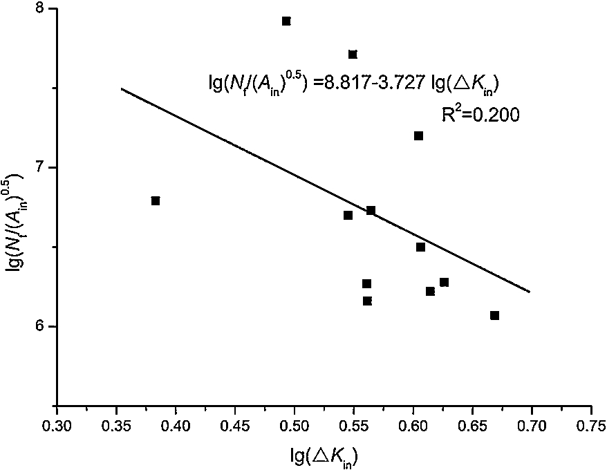
The fitting result of test data by the Paris law.
According to Fig. 11 and Eq. (1),
It can be concluded that:
The fatigue behavior and mechanism of FV520B-I and FV520B-S are very different and determined by heat treatments. The S–N curve of FV520B-I continuously descended and can be divided into two sloping lines for crack initiation site transition from the surface to the subsurface. The S–N curve of FV520B-S was far below FV520B-I’s, and there was a conventional fatigue limit. In the VHCF regime, most cracks of FV520B-I initiate from the subsurface inclusion, and a few cracks initiate from the surface or subsurface matrix. And the soft ferrites seem to the cause of FV520B-I cracks initiation from the subsurface matrix.
The fatigue life in the VHCF regime increased with an increase of the GBF diameter, and the relationships of the fatigue life with the other characteristic area sizes were not evident. The initiation life of crack initiation from subsurface inclusion may not the main portion of the fatigue life in the VHCF regime, and the fatigue life in the VHCF regime is mainly used up in the formation of the GBF.
The prediction of fatigue life in the VHCF regime based on crack propagation in the GBF according to the Paris law is not ideal. A new method for prediction of the fatigue life in the VHCF regime should be developed.
Footnotes
Acknowledgements
The authors gratefully acknowledge the financial support provided by the National Key Basic Research and Development Program (973 Program 2011CB013401). Thanks to Dr. Edward C. Mignot, Shandong University, for linguistic advice.