
Abstract
In this study the finite element method is used to analyse the performances of bonded composite wrap repair in cracked pipelines. Parametric analysis was performed in order to highlight the effects of the geometrical properties on the repair efficiency. The obtained results show that the optimization of the geometric properties of the wrap is still required to best improve the quality of repair.
Introduction
The oil and gas transported by steel pipelines in the industry are better than the storage tanks. The operating conditions are subjected to hard environments and extreme loading conditions. Mechanical damages are common in operating pipelines. They are damaged in the coating, erosion and corrosion which can lead to a principal problem the industry faces, namely an internal and external crack in the structure of the pipeline. According to the gravity of the problem, the harmful effects are the pressure bearing capability in the pipeline and they can reduce its lifespan or cause a failure of the structure [3,4,9,10,15]. The best means of reparation of canalization is the bonded composite wrap because it is installed during the continuous flow of the fluid and no hot work is done in order to avoid the risk of explosion. The use of the composite wrap as an alternative by the replacement of the cracked pipe often saves economical resources to immediately pay behind costs of repair [8,11,13,14,17]. After the realization of 2 to 65 composite wrap repairs on pipelines larger than 300 mm of outer diameter can save 15.000 to 780.000 m3 of natural gas by year. In choosing the composite wrap, 4.106 m3 of gas during 5 years is saved.
Numerical methods, such as the finite element method (FEM), have grown considerably in recent years. Several authors have used this method to analyse the performance of pipe repair by a composite patch [2,5–7,18]. The majority of these authors have used the linear mechanics of fracture approach to evaluate the reduction of stress intensity around the crack front by the composite wrap. Benyahia et al. [5] calculated the stress intensity factor (SIF) at the front of a repaired crack with bonded composite wrap in pipe subjected to internal pressure. They showed that the composite wrap repair leads to a significant reduction of the SIF which improves the service life of the cracked pipe. The same conclusions were made by Bezzerrouki et al. [6] who studied the performances of bonded composite wrap on pipes subjected to traction. However, for pipes subjected to bending moment, the repair efficiency is less significant according to Achour et al. [2]. The design of the bonded composite wrap for repairing damaged pipeline has not been studied extensively in the literature.
The objective of this work was to propose and analyse the technique of pipeline reinforcement cracked by composite wrap. To achieve this objective, a finite element study is used to analyse the performance of cracks repaired with composite patches by calculating the crack stress intensity factors in elastic behaviour. The effect of the geometrical properties on the reduction of the stress intensity at the crack tip is also analysed.
Model description and mechanical properties
Consider material alloy often used in gas pipelines, API 5L grade X65 containing a longitudinal external semi-elliptical crack of length (2c = 15.4 mm) and depth (a = 2.8 mm), it is repaired with a glass-epoxy composite wrap, the fibres are all oriented at 0° stuck around the entire circumference of the pipeline (Fig. 1). The geometrical and mechanical characteristics of the pipeline, the composite wrap and the adhesive are shown in Table 1 and 2, respectively.
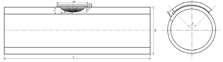
Repair by composite wrap of a semi-elliptical crack in a pressurized cylinder.
Dimensions of typical repair of pipeline
The pipeline is modelled in the commercial finite element software Abaqus [1]. Continuum elements with eight nodes and reduced integration (C3D8R) were used throughout the model. The total number of elements generated for the model was 686950. The mesh is refined at the crack front, composite wrap and adhesive layer. The model is shown in Fig. 2.
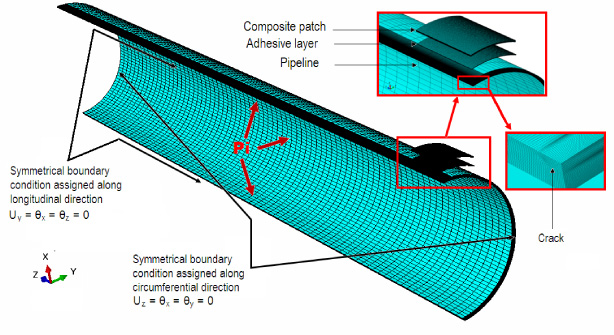
Finite element model of repaired crack by composite wrap.
Due to the symmetrical geometry of the repaired pipe and boundary/loading conditions, the model can be effectively simplified as a quarter symmetry structure (half in length and half in circumference). The internal surface of the pipe is subjected to internal pressure with different amplitudes (Pi = 2; 4; 6; 7.5 and 10.5 MPa), as is shown in Fig. 3. The reflective symmetry conditions are applicable along longitudinal (U Y = 𝜃 X = 𝜃 Z = 0) and circumferential direction (U Z = 𝜃 X = 𝜃 Y = 0) of quarter cylinder, as is shown in Fig. 4.
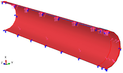
Pipeline under internal pressure.
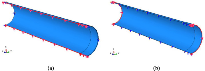
Reflective symmetry conditions. (a) Longitudinal direction, (b) Circumferential direction.
In Abaqus standard, the contact behaviour between three instances in an assembly (pipe, adhesive and composite wrap) can be defined by specifying an appropriate interaction property (normal and tangential) between the surface-to-surface contacts.
The virtual crack closure technique (VCCT) was used to extract the stress intensity factor at the crack front. The VCCT is based on the energy balance proposed by Irwin. In this technique, SIF are obtained for three fracture modes from the equation [12]:
The VCCT method for energy-release rate calculation supports the following material behaviors: linear isotropic elasticity, orthotropic elasticity and anisotropic elasticity.
The accuracy of the VCCT calculation depends on the meshes [12]. To ensure the greatest accuracy, equal element sizes should be used ahead of and behind the crack-tip node. The mesh size affects the solution; therefore, it is helpful to examine mesh-size convergence prior to attempting the finite element solution. Convergence tests on the effect of mesh size and element number were performed to ensure calculation accuracy and optimize computing time.
In our study, three cases were analysed: the first consists to analyse the effects of the geometrical parameters such as the length, the thickness and especially the width or the recovery angle of the composite wrap bonded on longitudinal semi elliptical crack. In the second case, we examined the effect of adhesive thickness on the evolution of the mode I stress intensity factor (K I ). In the third case, the effect of the adhesive shear modulus on the variation of stress intensity factor (SIF) at the crack front is highlighted. The case of the unrepaired pipe is presented as a reference.
Figure 5 presents the variation of the SIF as a function of the internal pressure for different wrap lengths. From this figure, it can be noted that the presence of the composite wrap reduces the SIF at the crack front which can improve the lifespan of the pipe. This reduction of the SIF is due to the stress transfer between the pipe and the composite wrap throughout the adhesive layer. The SIF increases as the service pressure also increases. About the wrap length effects, it can be noted that longer composite wraps give weak stress intensity factors and consequently best repair efficiency. This is because with longer composite wrap the bonded area increases and the stress transfer from the pipe toward the composite wrap will be more significant.
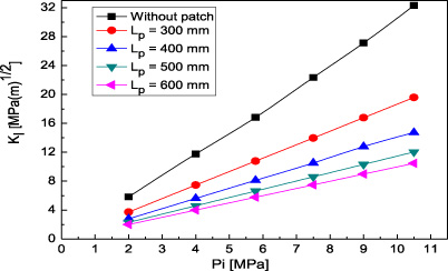
SIF vs internal pressure for different wrap lengths.
We have also analysed the influence of the thickness of the wrap on the SIF variation of repaired crack in pipeline with composite wrap. We considered several thicknesses of the wrap t p which vary between 6 mm to 12 mm, for a wrap length of 600 mm and a total overlap angle 𝛽 of 360°. Figure 6 presents the variation of the SIF at the front of the repaired crack as a function of the internal pressure for different wrap thickness. The analysis of this figure shows that an increase in the thickness of the wrap causes a decrease in the stress intensity factor. These results are in agreement with those of Bezzerrouki et al. [6]. If a thicker wrap is used, the stress level at the crack front decreases. This behaviour can be explained by the fact that the bonded composite wrap significantly reduces mechanical energy, highly concentrated at the crack front which reduces the velocity of propagation of this defect. This reduction is more significant when the wrap thickness increases.

SIF vs internal pressure for different wrap thickness.
The effect of the wrap recovery angle is illustrated in Fig. 7, this parameter varied between 30° and 360°. The length and thickness of this repair material used in this section has the following values: 600 mm and 12 mm respectively. We observed that an increase in this angle leads to a decrease in the stress intensity factor. This effect is more pronounced for a total recovery angle 𝛽 = 360°. Indeed, an increase of 33% in the wrap recovery angle leads to a reduction of the SIF about 37%.
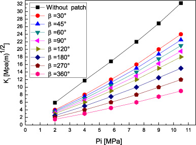
SIF vs internal pressure for different recovering angle.
The effects of the adhesive shear modulus and its thickness on the repair efficiency were also studied. Figure 8 shows the evolution of the SIF as a function of the internal pressure for different adhesive shear modulus G a ranging between 1120 MPa and 4200 MPa, the adhesive thickness t a = 0.1 mm, the wrap length L p = 600 mm, the wrap thickness t p = 12 mm and the total recovery angle of the wrap 𝛽 = 360°. It is observed that the increase of the shear modulus causes the reduction of the SIF at the crack tip. This result is in line with the study by Benyahia et al. [2].
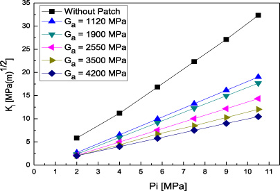
SIF vs internal pressure for different shear modulus of adhesive.
Figure 9 presents the variation of the SIF as a function of the thickness of the adhesive having a shear modulus G a between 1120 and 4200 MPa. It is noted that a reduction in the thickness of the adhesive leads to a decrease in the SIF. The relative difference in the SIF between t a = 0.1 mm and 0.2 mm, is of about 10% (for G a = 4200 MPa), which means that a small thickness of the adhesive increases the load transfer to the composite wrap. An optimization of the adhesive thickness is recommended in order to avoid the failure of the adhesive layer.

SIF vs thickness of adhesive for different shear modulus of adhesive.
The objective of our study was to highlight the performance of the composite wrap repair technique in a pipeline subjected to internal pressure. The effects of the different geometrical parameters of the wrap and the shear modulus of adhesive on the repair efficiency were studied. The increase in the length of the wrap causes the decrease in the SIF of the longitudinal crack; the use of a longer wrap in the axial direction is therefore beneficial for repair structure. An increasing of the wrap thickness leads to a decrease of the SIF at the crack tip. In addition, increasing the recovery angle of the wrap on the outside circumference of the pipeline eliminates the free edge effect and consequently reduces the SIF at the crack front. On the other hand, the SIF decreases significantly for higher adhesive shear modulus because of the load transfer from the repaired pipe to the wrap which can extend the lifespan of this structure. Finally, the reduction of the SIF at the crack tip is greater for small adhesive thicknesses, since the decrease in this parameter increases the magnitude of the stress concentration in the adhesive layer and facilitates their absorption by the composite wrap. All these parameters must be optimized in order to have the best repair efficiency.
Footnotes
Conflict of interest
None to report.