
Abstract
In the present work, the fracturing process in fiber-reinforced concrete beams subjected to seismic or generally repeated loadings is discussed, focusing on local phenomena related to the cracked cross-section. In particular, the residual crack opening in structural elements under cyclic loading is investigated. In this context, the Bridged Crack Model can take into account the concrete fracturing mechanism, as well as slippage and yielding of fiber reinforcement. A rigid-plastic constitutive law will be assumed for fibers, whereas for the matrix a linear elastic law, coupled with a fracturing condition according to Linear Elastic Fracture Mechanics will be utilized. In fact, a realistic fiber-reinforced concrete model should simulate an elasto-softening behaviour with the possibility of crack formation and propagation. The Bridged Crack Model is able to predict with accuracy the order of magnitude of some interesting quantities, such as the crack opening and closure in a beam cross-section, the residual crack opening, and the dissipated energy in the loading cycles.
Keywords
Introduction
In the case of modern, high-technology composite materials for civil engineering, such as fiber-reinforced ceramics and metal-matrix composites, in spite of the deeply different structural utilizations and the very heterogeneous mechanical and physical properties of the component materials, there are many similar features regarding the behaviour of cementitious-matrix and ceramic-matrix composites. In particular, the fundamental secondary-phase role in both cases is that of improving the fracture toughness of the brittle matrix by means of a bridging action affecting the matrix micro- and macro-cracks, so as to prevent their coalescence, opening and growth [17]. These bridging toughening mechanisms are due to debonding, sliding and frictional pulling-out between the matrix and the high-resistance discontinuous fibers or particles, and to yielding of the low-resistance ductile continuous fibers.
Knowledge of the structural behaviour of these new materials can lead to improvements in the material design through an optimization of the components. A fracture mechanics approach makes it possible to analyze the composite post-cracking behaviour and, unlike the classical strength theory, to explain certain discontinuous phenomena, that are experimentally verified, such as the size-scale effects or the snap-back and snap-through instabilities.
In the present work, an application of the Bridged Crack Model [1–4,8–13] is proposed for cyclic loading, which is able to explain and reproduce the constitutive flexural response of brittle matrix fibrous composites [14,16,18]. This response is often discontinuous owing to the presence of virtual catastrophic branches, i.e., snap-through branches with load control and snap-back branches with deflection control [5,7,8,15]. The bridging tractions are assumed as constant plastic forces, whereas the crack runs in an elastic brittle matrix. The effect of the size scale is found to be fundamental for the global structural behaviour, which can range from ductile to catastrophic simply with the variation of a dimensionless brittleness number, which is a function of the toughness of the matrix, of the yielding or slippage limit of the reinforcements, of the volume fraction of the reinforcement, and of a characteristic structural size [4,6,8]. When the matrix is over-reinforced, the crack propagates in a brittle manner across the specimen, while the bridging elements remain intact over most of the crack wake.
In addition, the Bridged Crack Model provides information about the global crack propagation, which, in the case analyzed here, appears unstable for low content of fibers or deep cross-sections, or for limited relative crack depths. More precisely, crack propagation is stable only for relative crack depths greater than a minimum value (varying slightly with the number of fibers), or may become stable only for brittleness numbers greater than a definite value [4,8]. The brittleness number is a dimensionless parameter which depends on the fiber yield strength, the matrix fracture toughness, the element’s size, and the reinforcement percentage:
Hysteretic behaviour of fiber-reinforced concrete elements
When a reinforced concrete beam is subjected to seismic or generally repeated loadings, it deteriorates in a progressive manner and its stiffness and loading capacity decrease sensibly. Such effects are the result of different damage phenomena, like crushing and fracturing of concrete or pulling-out and yielding of the reinforcements. A Fracture Mechanics model is then assumed, and loading and unloading processes will be considered [8,9]. Therefore, the phenomenon of shake-down due to slippage or plastic deformation of the fiber reinforcements can be studied. Up to a certain value of the bending moment, an elastic shake-down occurs; above this value, the shake-down becomes plastic, and a hysteresis loop is described by the stress-strain diagram of the structural element. Thus, the energy released in this dissipative phenomenon can be computed for each loading cycle.
It is worth noting that the assumptions regarding concrete as an elastic-perfectly brittle material and fiber as an elastic-perfectly plastic material, make it possible to avoid laborious iterative procedures, while at the same time they enable representation of the major nonlinear phenomena of the structural response, such as reduction of stiffnesses on account of propagation of the crack and plastic deformation of the reinforcement, the residual rotations upon unloading, and alternating plastic deformation.
Let us now examine a fiber-reinforced concrete beam subjected to a bending moment (Fig. 1) cyclically varying between M = 0 and M =

Fiber-reinforced concrete beam subjected to a bending moment.
In order to analyze the behaviour of the beam during the unloading process, we need to know the situation of the beam at peak load and then to impose suitable compatibility conditions to the crack opening displacement.
In particular, three different situations are possible:
(1) If the peak moment is lower than both the plastic flow (or slippage) moment and the fracture moment, the behaviour of the beam is linear-elastic.
(2) If the peak moment is greater than the fracture moment but lower than both the plastic flow moment and the slippage moment, since during the loading phase the crack remains closed in correspondence with the fiber, the compatibility condition has to ensure that the crack-opening displacement will remain zero during the unloading phase. In particular, when the applied moment is zero, the reaction of the fiber will vanish. Nevertheless, since during the loading phase the crack propagates, the stiffness of the beam will decrease.
(3) If the peak moment is greater than the moment of plastic flow, it is necessary to impose a compatibility condition for which the crack-opening displacement will remain constant during unloading up to reverse yielding. In particular, when the applied moment is set equal to zero, we have
Furthermore, if
From Eq. (1) the fiber reaction takes the form
The moment-versus-localized rotation response of the reinforced beam cross-section can be evaluated applying the above reasoning. In fact, the localized rotation, 𝜑, due to the crack, takes the form
In order to evaluate different moment-versus-localized rotation diagrams for a reinforced concrete section under cyclic loading, a loading control test and a rotation control test are herein simulated using the proposed model, highlighting the difference in local instability phenomena, and the evidences of the residual crack opening in the element cross-section, occurring when each unloading phase has been concluded.

Dimensionless moment-versus-rotation for N P = 1.0, and n = 10. The red curve is obtained by means of the Crack Length Control Scheme, whereas the black one represents the loading control. Blue circles indicate the yielding of the fibers.

Concrete element with ten fiber reinforcements under cyclic loading: Crack propagation from the first to the last fiber. Green fibers are considered as elastic, whereas orange ones are considered as plastic.

As a first case study, a concrete beam reinforced with 10 fibers (n = 10) is considered, and the numerical cyclic test is controlled by the imposed loading. During the unloading phase of the cyclic process, the minimum value of the bending moment is assumed in order to close completely the crack mouth of the damaged cross-section. The brittleness of the structural element is set as N P = 1, involving a hardening post peak branch [8], that is stable in loading control: a series of snap-through instabilities appear, which subtend the local softening responses (red curve in Fig. 2) only captured by the Crack Length Control Scheme [5,8].
Moreover, the phenomenon of shake-down due to slippage or plastic deformation of the fiber reinforcements is pointed out in Fig. 2: a hysteresis loop is described by the dimensionless moment-versus-rotation diagram of the beam cross-section. Thus, the energy released during this dissipative phenomenon can be computed for the hysteretic cycle.
During the loading phase (Fig. 3), the fiber bridging action keeps the crack closed at the fiber level until its yielding force is attained. Then, crack propagation takes place, and the crack jumps from one fiber to another due to snap-through phenomena occurring due to the loading control test, as seen in Fig. 2.
In Figs 3–6, green fibers are considered as elastic, whereas the orange ones are considered as plastic.
At the beginning of the unloading phase (Fig. 5), the fiber behaviour switches back to the elastic field. As a consequence of the rigid-perfectly plastic behaviour, the fibers act as struts, and they keep the crack open until the compression limit is attained. When this condition is reached, the crack opening displacement starts decreasing. At the end of the unloading phase, the crack mouth is closed, but the fracture inside the beam shows a residual crack opening, evidenced by the analysis of the crack opening profile (Fig. 6). At this point, the decrease in the load is not allowed, because a crack mouth overlapping would arise.

Concrete element with ten fiber reinforcements under cyclic loading: Crack closing up. Green fibers are considered as elastic, whereas orange ones are considered as plastic.
Concrete element with ten fiber reinforcements under cyclic loading: Residual crack opening.
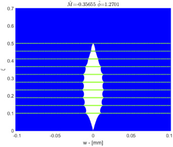
As a second case study, the residual crack opening phenomenon is studied for a concrete beam reinforced with 3 fibers (n = 3), and the numerical cyclic test is controlled by the rotation. The brittleness of the structural element is set as N P = 0.4, involving a softening post peak loading branch [13] that is stable due to the rotation control: a series of snap-back instabilities appear, which subtend the local softening responses with positive slope only captured by the Crack Length Control Scheme [5,8] (red curve in Fig. 7).
Furthermore, the phenomenon of shake-down due to slippage or plastic deformation of the fiber reinforcements is pointed out in Fig. 7: a hysteresis loop is described by the dimensionless moment-versus-rotation diagram of the beam cross-section, and the energy released during this dissipative phenomenon can be computed for the hysteretic cycle.
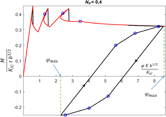
Dimensionless moment-versus-rotation for N P = 0.4, and n = 3. The red curve is obtained by means of the Crack Length Control Scheme, whereas the black one represents the rotation control. Blue circles indicate the yielding of the fibers.
During the loading phase (Fig. 8), the fiber bridging action keeps the crack closed at the fiber level until its yielding force is attained. Then, crack propagation takes place, and the crack slowly grows without jumps, as in the previous case, due to the rotation control test.
In Figs 8–11, green fibers are considered as elastic, whereas the orange ones are considered as plastic.
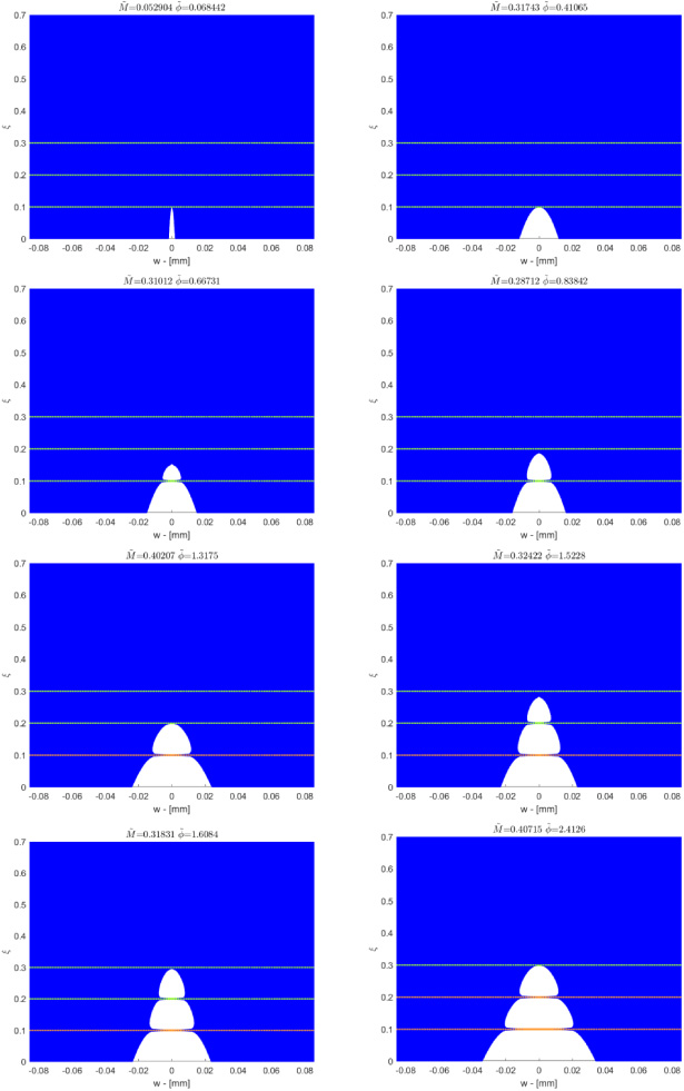
Concrete element with three fiber reinforcements under cyclic loading: Crack opening profiles. Green fibers are considered as elastic, whereas orange ones are considered as plastic.

At the beginning of the unloading phase (Fig. 10), the fiber behaviour switches back to the elastic field. As a consequence of the rigid-perfectly plastic behaviour, the fibers act as struts, and they keep the crack open until the compression limit is attained. When this condition is reached, the crack opening displacement starts decreasing. At the end of the unloading phase, all fibers have reached their inverse plastic strength, and the beam shows a residual crack opening, evidenced by the analysis of the crack opening profile (Fig. 11).

Concrete element with three fiber reinforcements under cyclic loading: Crack closing up. Green fibers are considered as elastic, whereas orange ones are considered as plastic.

Concrete element with three fiber reinforcements under cyclic loading: Residual crack opening.
In this work, the behaviour of a fiber-reinforced brittle-matrix cross-section subjected to seismic or generally repeated loadings is discussed, focusing on the phenomenon of the residual crack opening. This analysis is based on Fracture Mechanics concepts applied to the cyclic loading behaviour of fiber-reinforced concrete cross-sections. The proposed model considers the elementary phenomena of propagation of a crack, yielding or slippage of fibers, plastic shake-down and hysteresis, and defines the structural response by means of a simulation of a process of loading and unloading. Thus, the residual crack opening displacement values are defined on a mechanical basis, and the set of crack opening profiles is discussed for a loading control and a rotation control numerical test. Moreover, the Bridged Crack Model is able to predict with accuracy the order of magnitude of some interesting quantities, such as the crack opening and closure in a beam cross-section, the residual crack opening, and the dissipated energy in the loading cycles.
Footnotes
Acknowledgments
The authors gratefully acknowledge the effective support of their student Giulio Baffa Giusa.