
Abstract
In this paper, the problem of two unequal collinear semi-permeable cracks in a piezo-electromagnetic media is proposed and addressed mathematically using a complex variable technique. The problem is mathematically modeled as a non-homogeneous Riemann–Hilbert problem in terms of unknown complex potential functions. The solutions to the fracture parameters are obtained in explicit forms by solving the Hilbert problem. An illustrative numerical case study is presented for poled BaTiO3-CoFe2O4 ceramic cracked plate to show the effect of volume fractions, prescribed loads and inter-crack distance on fracture parameters.
Introduction
Piezo-electro-elastic/Magneto-electro-elastic (MEE) composite materials are widely used in e.g. magnetic field probes, acoustic, medical ultrasonic imaging, hydrophones, electronic packaging, electromagnetic sensors, actuators and transducers due to their multifield-coupled effects. MEE ceramics are brittle in nature and have low fracture toughness. The presence of defects such as cracks and voids lead to the premature failure of these materials under mechanical/electrical/magnetic loadings. Thus, fracture study becomes essential for such materials to predict structural integrity and to advance the design of MEE devices.
This article reviews extensive work that has been done to better understand the mechanics of MEE materials in the presence of defects such as cracks. As compared to piezo-electric or anisotropic cases, relatively limited work has been done so far in MEE fracture analysis. A large number of publications for a single crack in MEE materials are available in the literature [4,6,7,13–16,20,21,23]. However, few works related to multiple cracks in MEE media are available in the literature. It is also worth noting that problems of collinear cracks have been a typical and active topic in fracture mechanics. With the application of MEE ceramics, the collinear-crack problems in them have drawn the attention of many researchers [1,8,24]. The static and dynamic problems of two collinear interfacial cracks in MEE composites [25–28] have been solved by Zhou et al., who used the Schmidt method. Exact solutions for anti-plane collinear cracks in a MEE strip or layer have been derived by Wang et al. [19], Wang and Mai [18], and Singh et al. [11] under different conditions. Most recently Jangid and Bharagva [5] have derived an analytical solution for two collinear semi-permeable cracks in MEE media using Stroh’s formalism and complex variable technique.
The main objective of this article is to show the effect of volume fraction, inter-crack distance and prescribed loadings on the collinear semi-permeable cracks. For this, the problem of two unequal collinear semi-permeable cracks weakening a MEE media is studied. Only in-plane electromagnetic and mechanical loading conditions are considered. The problem is formulated employing Stroh’s formalism and solved using a complex variable technique. Closed form analytical expressions are derived for various fracture parameters.
Basic equations for piezo-electromagnetic media
The fundamental equations and the boundary conditions for linear piezo-electromagnetic media are defined below.
Constitutive equations
Kinematic equations
Equilibrium equations
Equilibrium equations for stresses, electric displacements and magnetic inductions in the absence of body forces, free electric charges and free magnetic currents, may, respectively, be written as
In the literature, mainly three crack face boundary conditions for MEE ceramics are available. These are represented mathematically as:
Impermeable boundary conditions (proposed by Deeg [2])
The crack faces are assumed to be traction free, electrically and magnetically impermeable
Permeable boundary conditions (proposed by Parton [10])
In this case, the crack is traction free and does not obstruct any electric field from conduction
Semi-permeable boundary conditions
This condition gives a more realistic boundary condition for open cracks. Its modification is proposed by Hao and Shen [3] for piezo-electric solids. These assumptions establish that the medium between the crack surfaces partially conducts the electric and magnetic fields and can be expressed as
For a two-dimensional problem all the field variables depend on x
1 and x
2.Therefore, introduce a generalized displacement vector
The column vectors of matrix
An infinite transversely isotropic piezo-electromagnetic 2D domain is considered for the analysis in the ox
1 x
2-plane. Two unequal collinear cracks L
1 and L
2 are taken along the x
1-axis occupying the intervals [d, c] and [b, a] respectively. The traction free crack face and semi-permeable boundary condition are taken for the analysis. The remote boundary of the plate is prescribed in-plane mechanical load
where, D c and B c are the electric and magnetic fluxes through the crack regions (d, c) and (b, a), which can be determined with the help of Eq. (8).

Schematic representation of the problem.
The continuity of
Consequently Eq. (19) may be written in component form for 𝛺2(z), 𝛺4(z) and 𝛺5(z), which yield the following scalar Hilbert problems
X 1(z), P 1(z) etc. are listed in Appendix A.
In this section, closed form analytical expressions are derived for crack opening displacement (COD), crack opening potential drop (COPD), crack opening induction drop (COID), stress intensity factor (SIF), electric displacement intensity factor (EDIF), and magnetic induction intensity factor (MIIF).
Crack opening displacement (COD)
The jump displacement vector 𝛥
Comparing the fourth component from Eq. (27) and using the value of 𝛺4(x
1) from Eq. (25) and integrating one obtains the COP drop, 𝛥𝜙(x
1), between the two faces of the crack as
Comparing the fifth component from Eq. (27) and using the value of 𝛺5(x
1) from Eq. (26) and integrating one obtains the COI drop, 𝛥𝜑(x
1), between the two faces of the crack as
Open mode stress intensity factor K
I
at the crack tips x
1 = d, b, c and a is obtained using the following formulae
Similarly, open mode EDIF, K
IV
, at the crack tips x
1 = d, c, b and a may be obtained as
Analogously, MIIF, K
V
, at the crack tips x
1 = d, c, b and a may be obtained as
In this section, the effect of inter-crack distance, volume fraction, and electric and magnetic loads are shown on various fracture parameters (discussed in the previous section).
Piezo-electromagnetic composite BaTiO3-CoFe2O4 is selected for the numerical case study considering BaTiO3 as inclusion and CoFe2O4 as matrix. The volume fraction of the inclusion is denoted by V
f
. The proportion of the two phases can be varied by adjusting the volume fraction of inclusion and the matrix. The elastic constants, dielectric permittivities and magnetic permeabilities, as well as piezo-electric and piezo-magnetic constants, are obtained by fraction rule (taken from Wang and Mai [17])
This rule cannot be applied to the determination of electromagnetic constants, since no electromagnetic coupling is present in any of the single phases. We assume the crack faces are semi-permeable (𝜅
r
= 𝛾
r
=1). The length of the bigger crack, L
1, smaller crack, L
2, prescribed mechanical load, electric displacement and magnetic induction are 2a
01(= 5mm), 2a
02(= 4mm),
Material constants for BaTiO3-CoFe2O4 for different volume fractions
Figure 2 depicts the COD profile over the crack surfaces for different inter-crack distances. It may be seen that the COD profile is increased as the inter-crack distance decreases; this is because of the mutual interactions between the two cracks. It may also be seen that the two cracks may get coalesced if the inter-crack distance decreases. Similarly, Figs 3 and 4 depict the COPD profile and COID profile over the crack surfaces for different inter-crack distances.
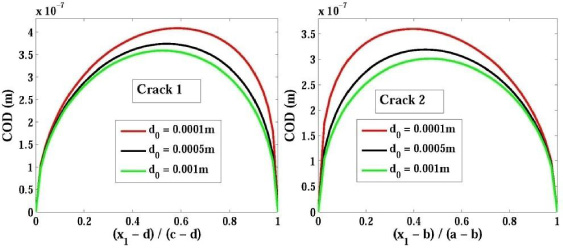
COD profile over the crack surfaces for different inter-crack distances.
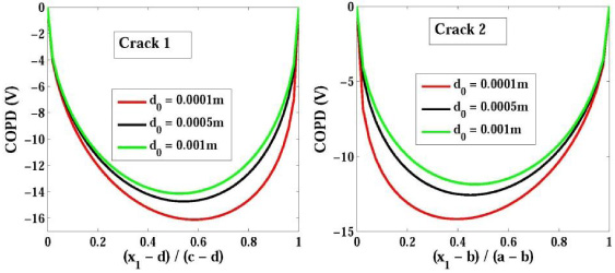
COPD profile over the crack surfaces for different inter-crack distances.
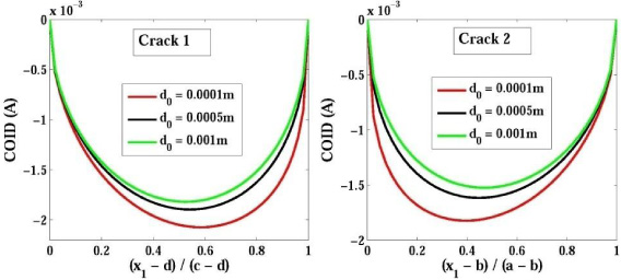
COID profile over the crack surfaces for different inter-crack distances.
Figure 5 shows the variation of stress intensity factors (SIFs) versus normalized inter-crack distance for different volume fractions. It may be seen that due to the mutual interactions of two cracks, the SIFs at the crack tips are increased as the inter-crack distance decreases. It may also be seen that SIF at the inner crack tips (at x 1 = c and x 1 = b) is higher compared to that at the outer crack tips (at x 1 = d and x 1 = a), which implies that the cracks will open more at the inner tips as compared to outer tips. Moreover, K I stabilizes for d 0∕a 02 ≥ 3. Also, SIF is decreased as the volume fraction increases. Similarly, Figs 6 and 7 show the variations of EDIF and MIIF versus inter-crack distance for different volume fractions.

Effect of normalized inter-crack distance on SIF for different volume fractions.

Effect of normalized inter-crack distance on EDIF for different volume fractions.

Effect of normalized inter-crack distance on MIIF for different volume fractions.
The effect of crack length a 02 on the stress intensity factor (SIF), K I , for different volume fractions is shown in Fig. 8. It may be seen from the figure that at the interior and exterior tips of the longer crack, K I increases at both tips as the crack length is increased. an increase in K I at the interior tip is more steep compared to the exterior tip. A similar variation is observed at the interior and exterior tips of the shorter crack. It should also be noted that for the half length of the crack equal to 2.5 mm (i.e., the length of both cracks is equal), the curves for K I at the interior tips of both cracks and exterior tips of the cracks become equal. Figures 9 and 10 show the same variations for EDIF and MIIF.
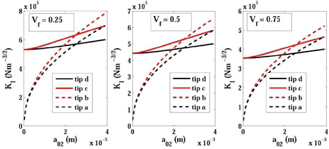
Effect of crack length a 02 on SIF for different volume fractions.
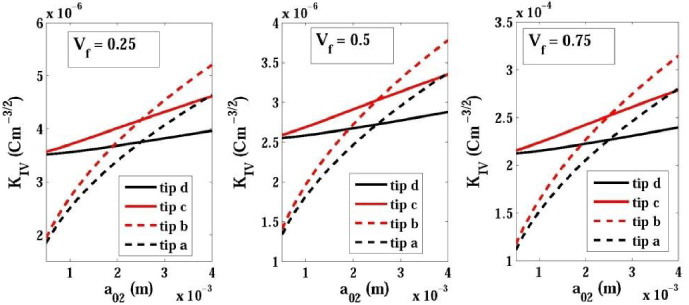
Effect of crack length a 02 on EDIF for different volume fractions.
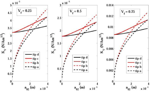
Effect of crack length a 02 on MIIF for different volume fractions.
Considering the aforementioned analytical and numerical studies done on the proposed model, the following conclusions can be drawn. A complex variable and Stroh’s formalism technique are successfully applied to study the two unequal collinear semi-permeable cracks in a piezo-electromagnetic media. The closed form analytic expressions are derived for the various fracture parameters such as COD, COPD, COID, SIF, EDIF and MIIF for the proposed model. To obtain the electric displacement and magnetic induction inside the crack gap media, two non-linear equations are derived. The effect of volume fraction is observed on the fracture parameters. All parameters are decreased when the volume fraction is increased. The effect of the inter-crack distance is observed on the fracture parameters. All parameters are increased when the inter-crack distance is decreased. The effect of crack length is observed on the fracture parameters. All parameters are increased when the crack length is increased.
Footnotes
Acknowledgements
The author would like to show his gratitude to the editor of this esteemed Journal. He is also immensely grateful to the reviewers for their comments on an earlier version of the manuscript.
Appendix A.
Appendix B.