
Abstract
The stability of bridges in the face of earthquake hazards has always been the focus of construction engineering. At present, a large number of bridge construction has begun to use isolation rubber bearings to increase the seismic capacity of bridges. However, in the face of high-intensity earthquake disasters, the seismic performance of the bridge is gradually unable to meet, the main reason is the lack of relevant research on the seismic performance of the bridge in high seismic intensity area. Therefore, this study will explore the changes of the bridge in the face of high-strength earthquake, and try to use high damping rubber bearings for the isolation design of the bridge. By establishing the finite element model of continuous bridge combined with isolation rubber bearing, the numerical calculation of bridge element is carried out on this basis, and the isolation effect of isolation rubber bearing is analyzed. The results show that the compression resistance and shear resistance of the isolated rubber bearing are strong. Under the influence of different seismic waves, the maximum displacement of the bearing is 0.131 m and the maximum horizontal force is 389.6 kN, which are lower than the allowable value of the bridge, and the overall seismic performance of the bridge has been significantly improved, which can play a good theoretical support in the construction of continuous bridges in high seismic intensity areas.
Introduction
As an important link in the traffic system, the bridge quality control and the shock absorption effect in the high earthquake area are particularly important, and the earthquake also has randomness and suddenness, so how to reduce the seismic impact of continuous beam bridge in the high earthquake area has become the research focus of the current construction industry. Liu et al. proposed a theoretical calculation method of constrained layer damping (CLD) bridge vehicle vibration and structural noise in 2018 by using modal strain energy method and statistical energy analysis, so as to increase the service life of the bridge and help the bridge face slight earthquake [12]. In the same year, Feng et al., using a group of real ground motions with different incidence angles, carried out the nonlinear time history analysis of a typical curved concrete bridge in China. It was found that with the increase of limit state, the influence of seismic excitation direction is more and more serious, which provides theoretical support for bridge earthquake prevention [4]. Shoushtari et al. studied the influence of vertical ground motion and biaxial excitation on the seismic response of bridge elements and connection elements. It was found that near fault earthquake had significant influence on some response parameters, and the design scheme was proposed [7]. Zhong et al. evaluated the optimal parameters of fluid viscous damper and proposed a system level brittleness evaluation method to evaluate the optimal parameters of fluid viscous damper of cable-stayed bridge, so that the bridge has better performance as a system [17]. Billah et al. have studied the establishment of seismic fragility curve of typical multi span continuous girder bridge in BC area, and used the seismic action corresponding to seismic risk as the input excitation of vulnerability evaluation to evaluate the seismic fragility of existing bridges, so as to optimize the bridge design [1]. In order to study the seismic response characteristics of Long-span Railway Continuous Girder Bridge located in high intensity area, Li et al. carried out nonlinear seismic response analysis on the research object. After seismic design, the difficulty of seismic design is reduced [9].
In addition to the study of bridge design to reduce the impact of earthquake, there are also many studies on the optimization of the damping device in the bridge to reduce the impact of earthquake. In 2020, Chang et al. conducted a comparative evaluation on the basic performance of existing isolation devices, and carried out compression test and compression shear test respectively, in order to achieve the balance between the cost-effectiveness and expected performance of the bridge under extreme load [2]. Wang et al. studied the hysteretic behavior of high damping rubber bearings under different non proportional plane loading paths, and found that non proportional plane loading would make the rubber of high damping rubber bearings have additional regional shear strain, resulting in different mechanical properties and hysteretic properties, so as to establish a model correction [13]. Olivier et al. studied the lateral stability and shear failure of natural rubber components used as bearings and isolation devices of bridges under actual axial compression [5]. In 2019, Xiang et al. observed that the earthquake disaster will cause the concrete shear key failure and bearing slip in the bridge, significantly increasing the risk of span instability, and proposed the economic yield steel damper to replace the traditional shear key as the restraint device on the bridge. It is verified that the proposed design method is quite effective in the seismic performance of the bridge [16]. In the same year, the team used energy dissipation devices to retrofit the existing bridges with lead rubber bearings (LRBs). Considering four different reinforcement measures, the team conducted brittleness analysis, evaluated the relative effectiveness of these devices in minimizing the seismic vulnerability of bridges, and selected the most effective reinforcement method [15]. By studying the seismic performance of high pier bridge system under near fault ground motion in earthquake prone areas of Southwest China, Chen established relevant numerical models. The results show that the performance of bridge is mainly determined by rubber bearings, and it is proposed that bearing failure should be carefully considered in engineering practice [3].
To sum up, bridge safety has always been the focus of international engineering research. Not only a large number of studies have analyzed bridge design problems to ensure the stability of bridges in earthquake, but also studies have pointed out that the performance of bridges is closely related to isolation devices. However, most of the studies only compare the performance of various isolation bearings, but few study the stability of rubber bearings in the face of high intensity earthquake. Therefore, this study will carry out isolation design for bridges in high seismic intensity area, select high damping rubber bearing as its isolation device, and carry out simulation numerical calculation, to explore whether its changes in isolation meet the isolation requirements, and analyze its performance. It is hoped that this paper will bring some theoretical support to the bridge construction in high earthquake intensity areas in China, and also promote the development of bridge engineering in China.
Design method of isolated structure
Dynamic principle of isolated structure
When the earthquake comes, the seismic wave will gradually transmit to the superstructure and cause the vibration of the structure, and the bridge is also affected by the earthquake. Combined with the high damping isolation rubber bearing structure, the bridge damage caused by seismic wave can be well isolated. The action principle of high damping isolation rubber bearing is to use the hysteresis characteristics of rubber layer to consume the excess energy, and at the same time, with the help of the characteristics of the structure, reduce the effect of seismic force through the natural vibration period [10]. The rubber can be reset by its own recovery ability. When an earthquake occurs, the mechanical model of the high damping isolation rubber bearing can be simplified as shown in Fig. 1.
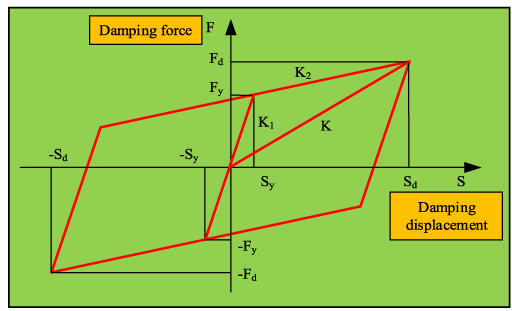
Restoring force model of high damping rubber bearings.
K in Fig. 1 represents the horizontal equivalent stiffness of the bearing, K
1 represents the stiffness before yielding, K
2 represents the stiffness after yielding, S represents the yield displacement of the rubber bearing, the designed damping displacement is expressed as S
d
, the yield force of the rubber bearing under stress is expressed as F
y
, and F
d
is the design damping force. The calculation formula of K, K
1 and K
2 is shown in Eq. (1).
The commonly used isolation structure design is divided into overall design and distributed design. The two design methods have their own advantages and disadvantages; distributed design is to model the components of the structure separately and use the unified damping coefficient to design [14]. The isolation design process of high damping rubber bearing is shown in Fig. 2. The figure that the high damping rubber structure is designed by using the distributed design method. Firstly, based on the design objective, a horizontal damping coefficient is set, and then the superstructure is arranged. Secondly, the rubber bearings and dampers are selected for the design and layout of the isolation layer, and the corresponding calculation method is selected to determine the isolation coefficient of the rubber bearings. The vibration mode decomposition response spectrum method and the time history analysis method are respectively used to calculate the damping coefficient of the rubber bearings, and then compared with the assumed value. If the requirements are met, the seismic simulation calculation will be carried out. If not, the seismic isolation layer layout will be redesigned. At the same time, if the simulation calculation does not meet the requirements, the seismic isolation selection and layout design will be redesigned until the requirements are met. Finally, the upper structure is designed, and the final isolation structure is adjusted, and the connection mode of isolation rubber structure is designed.
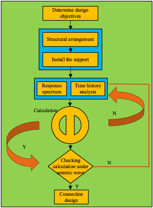
Design process of high damping rubber bearing isolation structure.
For the high damping isolation structure, it is divided into the upper and lower structure. The two parts of the structure are separated by the rubber bearing isolation layer as a sub structure of the whole. In the analysis, only the influence of the basic vibration mode can be considered, so the structure is simplified as Fig. 3. This figure is a simplified diagram of the bridge structure with high damping rubber bearings, which has been simplified as a regular structure with two degrees of freedom. As can be seen, the bridge isolation structure is divided into upper and lower parts by high damping rubber bearings. The upper part is the main beam structure, and the lower part is the cap beam and pier structure. Under the action of seismic wave, the dynamic motion equation of two degree of freedom isolated bridge can be expressed as follows:
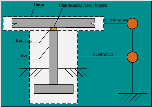
Simplified calculation model of isolated structure.
Taking 4 cases in Xinjiang as an example, modeling and analysis are carried out for a 40 m prestressed concrete beam bridge, which is simply supported and then continuous. The total length of the bridge is 160 m. The finite element software is used to establish the beam bridge model, as shown in Fig. 4, in which the main beam and pier are three-dimensional beam elements. As shown, the model of continuous beam bridge is established by designing five piers, and the main beam and piers are connected by high damping isolation rubber bearings. The coordinate system used in the model is the world coordinate system, with X axis along the bridge direction, Y axis perpendicular to the bridge direction, and Z axis in the longitudinal direction. When an earthquake occurs, the displacement change of high damping rubber bearings is calculated by Eq. (5).
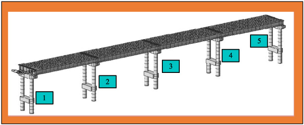
Finite element model of bridge.
The response spectrum represents the maximum displacement and velocity response curves of the structure in the single degree of freedom system in each period, and the acceleration response is also included, which changes with the change of the particle. That is to say, if we can get the maximum response of structural mass and damping of multi degree of freedom system in each single degree of freedom in the strong earthquake environment, then the natural frequency of the border is taken as the X axis, and the response changes of velocity, acceleration and displacement are taken as the Y axis to draw the curve, we can get the seismic response spectrum curve, and the acceleration is generally used as the Y axis in the research.
In the calculation, the seismic action is regarded as the internal force of calculating the seismic response of the vibration mode, and it is regarded as a kind of lateral load attached to the isolated rubber bearing structure. The traditional static calculation method is used to calculate the seismic response, and the displacement and internal force of the structure under the vibration mode can be obtained in this way. When an earthquake occurs, the maximum horizontal shear force on the structure is the seismic horizontal force, and its calculation method is shown in Eq. (7).
Generally, in software analysis, we need to choose according to the rigid body and flexible response of the structure itself, and also need to consider the duration of the earthquake, which can make the calculation simple, the requirements of hardware are not high, and the requirements of the operator’s theoretical knowledge are not strict, but the single use of response spectrum modal analysis still has some shortcomings. Therefore, the time history analysis method is also added to analyze the seismic response of the structure.
The time history analysis method uses step-by-step integration. By directly integrating the ground acceleration at a certain time in the seismic wave with the vibration system equation, the velocity, acceleration and displacement of each particle at this time can be obtained, and then by analogy, from the direct integration of the earthquake to the disappearance of the seismic wave [11]. Through the time history analysis method, the amplitude, frequency spectrum and duration of seismic wave can be considered at the same time, and the influence of seismic environment on the structure can be calculated. The collapse damage and energy consumption that cannot be calculated by response spectrum can be obtained by nonlinear structural analysis. The dynamic equilibrium equation of time history analysis method is as follows:
Strength calculation results of rubber bearing materials
Before the isolation rubber bearing is applied to the actual pier, the performance of the isolation rubber material needs to be analyzed first, in order to ensure that the structural performance of the isolation rubber bearing can meet the design requirements, including the vertical compression stiffness and horizontal shear performance of the material, as shown in Fig. 5. Figure 5(a) is the compression stiffness test curve of the isolation rubber bearing. From the curve change, it can be seen that with the increase of vertical load, the growth rate of vertical displacement of the bearing begins to decrease, that is, under the trend of increasing pressure, the vertical displacement of the isolation rubber bearing will gradually reach a stable value, indicating that the isolation rubber bearing has good vertical bearing capacity. Figure 5(b) shows the horizontal shear performance analysis of the isolation rubber bearing. The curve shown is a hysteretic curve. From the change of the curve, it can be seen that in each overload test, the slope of the curve is inversely proportional to the load growth, and the curve recovers quickly during unloading, which directly shows that the isolation rubber bearing has strong shear resistance. In conclusion, the isolation rubber bearing designed in the study has strong compressive capacity and shear capacity, and has high stability in the face of vertical bridge load and horizontal shear caused by earthquake.
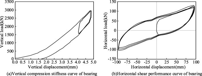
Structural performance analysis of isolation rubber bearing.
According to the design information of a bridge in Xinjiang used in the model design, the relevant literature shows that the continuous bridge belongs to B bridge, the basic vibration peak acceleration is 0.213 g, the characteristic period is 0.45 s, and the site coefficient is 1. The corresponding parameters of the bridge are added to the finite element model, and two seismic waves are selected to test this time. The waveform selection of seismic wave is shown in Fig. 6.
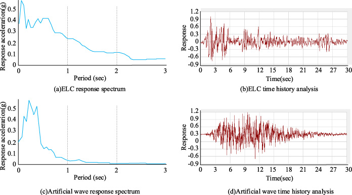
Seismic wave selection results.
Figure 6(a,b) are ELC seismic waves, in which Fig. 6(a) is the response spectrum curve of ELC seismic wave, and the ordinate is the acceleration of seismic wave. It can be found that the acceleration of the seismic wave is great at the initial stage of occurrence, the acceleration is large, the propagation is fast, and then the acceleration gradually decreases; Fig. 5(b) is the time history curve of ELC seismic wave. It can be seen that the response time of seismic wave reflected by the time history curve of ELC seismic wave exists and has obvious duration. Figure 6(c,d) are artificial seismic waves. Figure 6(c) is the response spectrum curve of artificial waves. Acceleration is also used as the ordinate. The acceleration does not increase as much as ELC, but increases slightly in the initial stage of seismic waves, rises to the highest point suddenly, and then drops precipically, and tends to zero between them; Fig. 6(d) is the time history curve of artificial wave. It can be seen that the response in the time history curve of artificial wave is mainly reflected in the first half of seismic wave, and shows a high response. Most of the responses of the two kinds of seismic waves are the same. The reason why we choose the two kinds of seismic waves is that we hope to verify the effect of high damping rubber bearings in bridge damping through two different seismic waves. In this way, two kinds of seismic waves are applied to the structural checking calculation, and the displacement checking calculation results of rubber bearing under the action of two kinds of seismic waves are shown in Table 1. As can be seen, under the action of ELC seismic wave, the maximum displacement of the rubber bearing installed in the transition pier along the bridge direction is 0.106 m, the maximum displacement of the vertical bridge direction is 0.088 m, and the allowable displacement of the bridge is 0.225 m, which indicates that the support displacement on the transition pier meets the requirements; The allowable displacement of the intermediate pier is 0.300 m, and the maximum displacement of the bearing in the forward direction and transverse direction under the action of ELC seismic wave is 0.115 m and 0.101 m respectively, which also meets the design requirements. In addition, under the action of artificial wave, the maximum displacement along the bridge direction of the transition pier is 0.114 m, and the maximum displacement across the bridge direction is 0.097 m, which also meets the design requirements; The maximum displacements along the bridge direction and across the bridge direction on the intermediate pier are 0.131 m and 0.112 m respectively, which are also within the allowable displacement. Based on the above data, it can be seen that the maximum displacement of the bridge structure with high damping isolation rubber bearing is far less than the allowable displacement, and the surplus displacement is large, which indicates that the rubber bearing has a strong isolation ability. At the same time, the anti-sliding ability of high damping isolation rubber bearing is analyzed, and the results are shown in Table 2. As can be seen, under the action of ELC seismic wave, the maximum horizontal seismic force along the bridge direction on the bridge transition pier is 214.8 kN, and the maximum horizontal seismic force across the bridge direction is 213.5 kN, which meets the allowable horizontal force; the maximum horizontal seismic forces along the bridge direction and across the bridge direction are 371.6 kN and 366.1 kN respectively, which also meet the allowable horizontal force of the intermediate pier. Under the action of artificial waves, the maximum horizontal seismic forces along the bridge direction and across the bridge direction of the transition pier are 218.6 kN and 216.3 kN respectively, which meet the allowable horizontal forces of the pier; in addition, under the influence of artificial waves, the maximum horizontal seismic forces along and across the bridge are 389.6 kN and 381.2 kN respectively, which also meet the allowable horizontal force of the intermediate pier. In conclusion, the use of high damping rubber bearings can well meet the seismic requirements of the bridge, and has a large allowable space under the influence of strong earthquake.
Checking calculation of bearing displacement under the action of ELC seismic wave and artificial wave
Checking calculation of bearing anti sliding ability under ELC seismic wave and artificial wave
The strength of bridge pier is checked by calculating the interface bending bearing capacity of pier under the influence of seismic wave. The change of bending bearing capacity of pier after installing isolation rubber bearing is judged by checking the strength of 5 piers of continuous bridge in the model. There are five piers in the bridge model, and each pier is divided into two piers at the same time. The average value of piers is not obtained from the checking calculation results, and the results are shown in Fig. 7. The average values of dead load axial force on piers 1–5 in Fig. 7 are 4032.8 kN, 6026.3 kN, 4845.3 kN, 6107.8 kN and 4002.5 kN respectively, and the average values of bending moment are 7181.2 kN/m, 7279.3 kN/m, 7176.1 kN/m, 7213.5 kN/m and 7188.8 kN/m respectively. It can be seen that the bending moment and dead load axial force of each pier are different, but the dead load axial force of No. 3 pier in the middle pier is slightly smaller than that of transition pier, but slightly larger than that of No. 1 and No. 5 pier; The bending moment of intermediate pier is similar to that of No. 1 and No. 5 pier, but slightly smaller than that of No. 2 and No. 4 transition pier. And it is not difficult to find that the dead load axial force and bending moment of all piers meet the requirements, which indicates that the pier after the installation of isolation rubber bearing has strong strength, which can reduce the occurrence of accidents and reduce economic losses. At the same time, the results of pier displacement checking calculation under the action of seismic wave ELC are shown in Table 3.
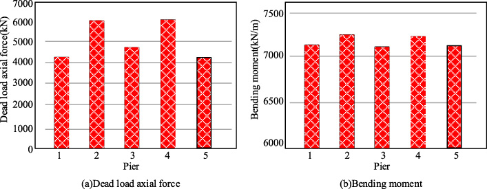
Checking calculation of pier strength under two kinds of seismic waves.
Checking results of pier displacement
It can be seen from Table 3 that the displacement along the bridge direction of the five piers under the influence of ELC seismic wave is small, and far less than the allowable displacement, which indicates that the isolation rubber bearing can play a good role in reducing vibration.
In order to verify the performance changes of the bridge after the installation of high damping rubber bearings, we can simulate the model, compare the changes of the bridge before and after the impact of strong earthquake, and discuss the damping effect of the bridge. In this study, simulated earthquake will be used to test the change of horizontal shear force on the bridge, and the difference between before and after isolation will be observed to judge the isolation effect of rubber bearings. The specific test results are shown in Fig. 8. Figure 8(a) shows the shear force comparison results before and after seismic isolation of the bridge along the bridge direction. It can be seen that the two seismic waves of seismic isolation act twice respectively. The shear force of the bridge before seismic isolation shown twice is larger, and the maximum shear force is 4931 kN, which appears at Pier 2; The minimum shear force is 4204 kN, which occurs in No. 1 pier, and the shear force of No. 1 pier and No. 5 pier is similar, the shear force of No. 3 pier and No. 4 pier is also similar, and the shear force of middle pier is 4655 kN. The shear force of the bridge before seismic isolation is far beyond the allowable shear force, which does not meet the requirements. The maximum shear force of the bridge after seismic isolation also appears in Pier 2, but its value is only 1701 kN, which is lower than the allowable shear force of 2282 kN. Figure 8(b) shows the comparison results of the shear force of the bridge in the transverse direction before and after seismic isolation. Similarly, the minimum shear force of the bridge before seismic isolation has reached 4461 kN, which is greater than the allowable shear force. When the rubber bearings are installed for seismic isolation, the maximum shear force in the transverse direction of the bridge is 1942 kN, which is less than the allowable shear force in the transverse direction of the bridge 2564 kN.

Comparison of horizontal shear force changes of bridge before and after seismic isolation.
Some studies have shown that the high damping performance of isolation rubber bearings has a good effect in isolation [8], and relevant studies have pointed out that the application of isolation rubber bearings in bridge design can well improve the seismic capacity of pier bridges [6]. However, the above research does not deeply analyze the design of rubber bearing under high and strong earthquake. In view of this, in the face of continuous bridge construction in high seismic intensity area, this paper puts forward a design method of using high damping isolation rubber bearing for bridge damping. By establishing the relevant model, the corresponding calculation method is proposed, and the effectiveness and feasibility of the new design method are verified by numerical calculation of bridge elements in the model. This new design method is based on the isolated rubber bearing, and then designs the bridge structure, through the damping device to reduce the impact of high-strength earthquake. The final experimental analysis results show that the material and structural properties of the isolation rubber bearing are good. In addition, only from the change of the isolation rubber bearing, under the influence of seismic waves, the maximum displacement of the rubber bearing is 0.131 m, which is within the allowable displacement of the bridge design, and has a large margin. In addition, the calculation results of bridge piers show that the bending moment and dead load axial force of bridge piers under the action of seismic wave also meet the requirements. By comparing the shear force before and after seismic isolation, it can be seen that the building size of the bridge after seismic isolation has been greatly reduced. To sum up, the seismic isolation rubber bearing device can be used in the seismic reduction design of bridges in high seismic intensity areas, which can well cope with the impact of high-intensity earthquakes. It has a good guiding significance for the construction of bridges, and is conducive to the development of high seismic intensity areas, and promotes the overall economic development of our country.
Footnotes
Conflict of interest
None to report.