
Abstract
High speed photography by Caustics method using Cranz-Schardin camera was studied for crack propagation and divergence in thermally tempered glass. Tempered 10 mm thick glass plates were used as a specimen. Two types of bifurcation and branching as the crack divergence could be observed and clarified even in 10 mm thick tempered glass. The difference of the shadow spot sizes between bifurcation type and branching type could be confirmed.
Keywords
Introduction
Tempered glass is a glass product which is manufactured of the glass surface layer under large compressive stress and the inner layer under large tensile stress. Due to these characteristics, it has 3–4 times the strength of ordinary flat glass, and it becomes fine fragments when fractured. The fragmentation phenomenon of the tempered glass at the time of fracture mainly contributes greatly to social recognition as a safety glass [7]. Analysis of crack propagation and divergence are extremely important, since the fragmentation is a phenomenon which is caused by crack propagation and divergence at the fracture of tempered glass.
However, there are many unclear points about fracture phenomena, especially the crack propagation and the divergence in tempered glass. The crack bifurcation as shown in Fig. 1 has been basically considered for the crack divergence of glass. Based on this bifurcation concept, the divergence mechanism of glass is often explained by two main approaches. One is “the concept as a means to release elastic energy after reaching the critical velocity” [9] and the other is “the concept based on the union of p-crack and s-cracks which were generated in a place not on the extension of the p-crack” [10]. The two concepts have not always been established, and there are many unclear points regarding crack divergence of glass.
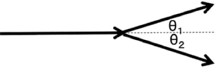
Ordinary crack divergence called bifurcation.
Oka [12] showed that there are two divergence types of bifurcation and branching for divergence phenomena in blood vessel, and stated that the divergence angle can be calculated from the principle of optimal design. The divergence angle of bifurcation was 51°, and that of branching was 90°. Also, the diameter dependence of the two blood vessels was clearly stated, namely bifurcation can occur when the diameters of two blood vessels after divergence have approximately the similar values, and branching can occur when those have greatly different values.
Aratani [2] also reported that the bifurcation as shown in Fig. 1 was confirmed to exist and the branching as shown in Fig. 2 also exists, relating to the divergence in tempered glass with a plate thickness of 3.5 mm. The divergence angle of tempered glass was about 28° on average for a bifurcation, and was about 52° for branching, that is smaller than the values calculated by Oka from the principle of optimal design, 51 and 90°. The large variation of divergence angle also could be confirmed in addition to its sharpening phenomenon.

Crack divergence of branching types.
Although two types of bifurcation and branching could be observed on the fracture in tempered glass, details of the difference are not known for sure. It is also necessary to investigate the energy of the propagating crack, including the consideration of the blood vessel diameter difference described by Oka. Cranz-Schardin high-speed camera [17] which was used for this observation can measure up to 1 million frames/s with 30 frames. Due to its measurement principle, there is always a time interval between the photographs taken. For this reason, there are many cases being impossible to make reliable analysis, especially the crack divergence and propagation direction.
Caustics method [15,21] is widely known as a method for measuring the dynamic stress intensity factor from the size of the shadow spot generated at the tip of the propagating crack. It started with the measurement polymer materials which stress optical coefficient is large. Schardin [14], who was involved in the development of this method with Manogg [11], used a shadowgraph method for high-speed photography of bending fracture for annealed flat glass. Takahashi et al. [16,20] reported shadow size change with crack propagation, by applying this method to annealed flat glass subjected to three-point bending impact.
Aratani et al. [4] also observed the dynamic stress intensity factor in tempered glass, and reported that the value of the dynamic stress intensity factor decreased to about 1/2 after the bifurcation. There is a possibility of more detailed estimation with conventional high-speed crack propagation by adding shadow spot information generated at the crack tip using the Caustics method. Few papers concerned with crack propagation in tempered glass which has a relatively thick of 10 mm reported. Research of the shadow spot information by the Caustics method and the crack propagation phenomenon were investigated by using tempered glass with a plate thickness of 10 mm as a specimen.
Specimens
Ordinary tempered glass that has passed the British standards BS-5282 [7] and the Japanese standard JIS-R3206 was used as a specimen. The specimen used was 900 × 400 × 10 (mm) in size, and a soda–lime–silicate float glass plate was used [2,4] produced by Central Glass Co. Ltd.
Test equipment and method
Figure 3 shows the experimental setup. It was observed using a Cranz-Schardin high speed camera [20] which was developed at the Research Institute for Applied Mechanics, Kyushu University. An extremely light impactor of 0.2 g and an air gun were used to minimize the deformation of the sample at the fracture start.
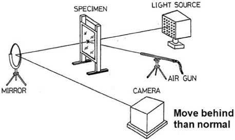
Experimental setup.
Figure 4 shows the principle of the Caustics method. The crack propagates from the bottom to the top of the figure, and stress due to crack propagation is generated at the front of the crack. Based on the generated stress, the parallel light incident in front of the propagating crack is refracted. A shadow spot can be observed at the reference plane by making the focus behind the ordinary specimen plane. In this measurement, the distance between the specimen plane and the reference plane was set to about 1.5 m.
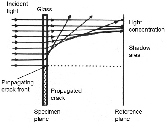
Principle of Caustics method.
Conventionally, a technique of sensitized development (ASA 200 → 800) has been used in order to make photographs clear. Photographs were captured with a film scanner 400-SCN024 made by Sanwa Supply Inc. and were analyzed by clarifying using image processing software. The image quality of photographs could be improved significantly by adopting above method, compared with the conventional method of sensitized development.
Furthermore, black and white colors were reversed and analyzed for making the state of shadow spots and crack propagation as clear as possible in many photographs. Namely, it should be noted that shadow spots and propagated cracks are shown in white.
Results and discussion
Occurrence of shadow spots and crack divergence
Figure 5 shows a high-speed photograph which was photographed by Caustics method and processed by reversing black and white for clarifying shadow spots and crack propagations. Figure 5(b) is a photograph about 5 μs after Fig. 5(a). By comparing the two photographs, it is possible to observe crack propagation in tempered glass. Using Caustics method, dynamic stress intensity factor, that is, the propagation energy of the crack can be estimated, in addition to “propagation situation at crack tip” and “crack pattern after crack propagation” which information obtained by general high-speed photography.
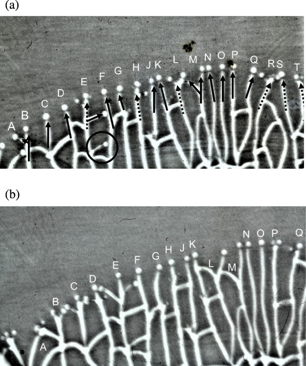
Example of black and white reversed photograph observed by Caustics method.
Focusing on 19 cracks named from crack A to crack T, they were marked with arrows that indicated the direction of propagation as shown in Fig. 5(a). Crack A could be confirmed that it diverged from crack B and then propagated. Since the propagation direction of crack B before and after divergence was the similar, it could be determined that the divergence of cracks A and B was a branching type. Cracks C, D, F, G, J, K, M, N, O, P and Q were observed to propagate without divergence and also they only had one shadow spot each.
In addition to the size of the shadow spot, its occurrence state is also important, but there were some aspects that were difficult to observe and judge by the analysis by Caustics method. Therefore, the information with shadow spots generated was clarified by using the arrows which indicate the direction of crack propagation. That is, it was indicated by the solid line when the number of shadow spot at the tip of a propagating crack observed was one, and that was indicated by a dashed arrow when the numbers of shadow spots were two or more.
Although generation of a shadow spot was observed at the tip of crack E, generations of a small shadow spot on the left side and a smaller shadow spot on the right side of crack E were also observed. From the position of the shadow spot, it can be estimated that the left-side shadow spot would be generated and then the right-side shadow spot would be generated.
Small shadow spots were observed on the tip of crack H and on the right side thereof. A shadow spot of the crack diverged to the left side from crack M was also observed on the crack slightly rearward from the tip of propagated crack L. After the bifurcation of crack M, the crack on the left side collided with crack L and stopped.
It was confirmed that the shadow spots generated at the tip of each propagating crack had crack divergence information. Namely, cracks A, B, C, D, F, G, J, K, M, N, O, P and Q were indicated by a solid arrow and were confirmed to propagate without divergence by the next photograph as shown in Fig. 5(b). On the other hand, cracks E, H and L were indicated by a dot arrow and were observed to generate crack divergence immediately by the next photograph. Furthermore, the cracks after the divergence would propagate to the direction of the shadow spot generated. It could be confirmed that the generation of multiple shadow spots indicated the new crack generation and the subsequent crack propagating direction. The divergence type of crack L could be judged bifurcation type from the pattern of divergence.
It was possible to easily observe a secondary crack [5] that was generated with a time delay. The crack circled in Fig. 5(a) was the secondary crack. Since the generation of shadow spot could be observed at the tip, the crack was observed to be propagating in this photograph. It could be also estimated that this was a secondary crack, because there was a large distance from the propagating cracks concentrically at the tip, and this crack could not observe in the photograph before 5 μs. The number of cracks after fracture in tempered glass is extremely large, and it is not easy to understand the occurrence of secondary cracks even when taking a technique of high-speed photography. Using Caustics method, however, the generation of secondary cracks can be detected easily from the generation of shadow spots.
It could be observed of “generation of divergence” and “propagating direction” using Caustics method in addition to “propagating situation at crack tip” and “crack propagated pattern” which information is obtained by general high-speed photography. As the propagated direction would be inferred from the position of shadow spot generated in the high-speed photograph and could be confirmed in the next photograph, highly accurate crack propagating information can be obtained. Namely, it is also possible to estimate the crack propagating direction thereafter in adding with the measurement of dynamic stress intensity factor, using shadow spots generated by Caustics method.
However, it is necessary to be careful about shadow spot change after divergence. As a large tensile stress is applied to cracks during propagating in tempered glass, the crack propagation phenomenon and increase of the propagation energy basically proceed at the same time. Therefore, even if the propagation energy temporarily drops due to divergence, the propagation energy sometimes increases as the crack propagates. This means that the size of the shadow spot after divergence changes with the crack propagating condition, especially the crack propagational distance and the stress field. The location of shadow spots will be discussed in detail in Section 3.5.
The specimen of this experimental used was 10 mm thick, which is belonged in a relatively thick category as a tempered glass. Two types of divergence which are called bifurcation and branching, could be observed even in tempered glass that belongs such in a thick category.
It could be seen that some cracks had a bifurcated divergence appearance, observing in the previous section. For example, it could be inferred from the crack propagation pattern that crack L and crack M were bifurcated. On the other hand, crack P had the occurrence of bifurcation which could be estimated from two shadow spot generation and the observation of the next high-speed photograph.
Focusing on crack L, the shadow spot immediately after the crack divergence could be observed in Fig. 5(a) which 5 μs before Fig. 5(b). The enlarged view is shown in Fig. 6. Figure 6(a) is an enlarged view of Fig. 5(a), and Fig. 6(b) is an enlarged view of Fig. 5(b). The size of the shadow spot of crack L was about 4.3 mm and about 4.5 mm, respectively. While confirming that divergence of crack L was the bifurcation type, the size of the shadow spot at the crack tip on the right side was about 4.6 mm after propagating about 15 mm. On the other hand, the crack on the left side collided with the preceding crack K, and the crack could be observed in a stopped state.
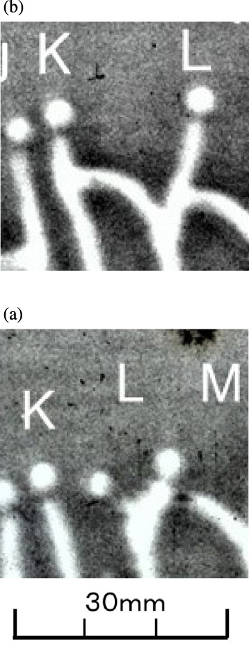
Magnified photographs of crack L.
Figure 7 shows an enlarged photograph of the shadow spot of crack M. Figure 7(a) is a photograph immediately after divergence, and Fig. 7(b) is a photograph 5 μs after that. The sizes of the shadow spots which propagated 5 mm after crack divergence were both about 3.9 mm. After 5 μs, the sizes of shadow spots after divergence were about 4.2 mm on the left side and about 3.9 mm on the right side from Fig. 7(b).
Magnified photographs of crack M.
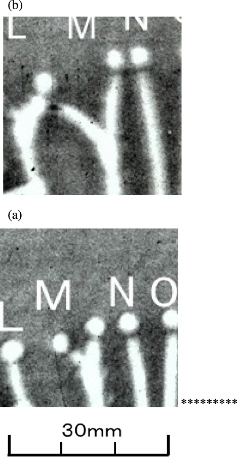
Figure 8 shows an enlarged photograph of the shadow spot of crack P. The sizes of the shadow spot were about 3.6 mm and about 3.9 mm in Fig. 8(a), respectively. The shadow spots in Fig. 8(b) after 5 μs were both about 4.2 mm, and the crack propagation distance was about 10 mm from the crack divergence.

Magnified photographs of crack P and crack Q.
As shown in the above example, the shadow spots at the tip of the bifurcated crack had almost the same size, and this tendency was the similar in other bifurcations.
It was reported [2] that not only bifurcation type but also branching type occurred in the crack divergence phenomenon of 3.5 mm thick tempered glass. A similar tendency was recognized even 10 mm thick tempered glass belonging to the relatively thick category. The crack Q shown in Fig. 8 corresponds to the branching type. The size of the shadow spot of the trunk crack was 4.9 mm, and that of the branch crack was 2.6 mm from measuring as shown in Fig. 8(a). On the other hand, three shadow spots were observed at the tip of the trunk crack after branching from Fig. 8(b). Since the shadow spot of the branch crack overlapped with crack P, there were something unclear. However, it could be inferred that the propagation energy in trunk crack recovered until the branching generating level.
The crack divergence of branching in crack E is shown in Fig. 9. Figure 9(a) is a photograph immediately after branching, and Fig. 9(b) is a photograph 5 μs after that. Two shadow spots were observed at the tip of the propagating crack as shown in Fig. 9(a). The size of the shadow spot that would be become a trunk crack was about 4.9 mm, and there was a shadow spot with a size of about 2.3 mm on the right side that would be become a branch crack. In addition, a shadow spot of about 3.6 mm was also observed in front of these shadows. On the other hand, the shadow spot size of the trunk crack and the branch crack was both about 4.2 mm from Fig. 9(b). In addition, the shadow spot the size of the branched crack in the foreground was approximately 3.9 mm. It was also inferred that the propagation energy of the branch crack immediately after divergence was much smaller than that of the trunk crack.
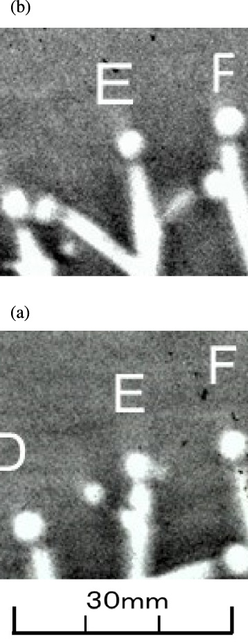
Magnified photographs of crack E.
The crack divergence of branching in crack G is shown in Fig. 10. Figure 10(a) is a photograph immediately after branching, and Fig. 10(b) is a photograph 5 μs after that. These photographs are about 35 μs before the photographs as shown in Fig. 5, and crack divergence in Fig. 10 could not be observed in Fig. 5. Three shadow spots were observed at the tip of the propagating crack in Fig. 10(a). The sizes of shadow spots were about 2.4 mm on the left side, about 3.2 mm in the center, and about 2.1 mm on the right side. These three shadows after 5 μs were about all 3.0 mm in size. The results seem to be different from the relationship between the trunk crack and the branch crack described above. As for the three shadow spots, it was observed from Fig. 10(b) that the crack in the center and the crack on the right diverged first, and the central crack and the crack on the left side diverged immediately after. The trunk crack propagating in the center was branched into right and left branches in a short time. Therefore, it is thought that there was no significant difference of relation between the trunk crack and two branch cracks.
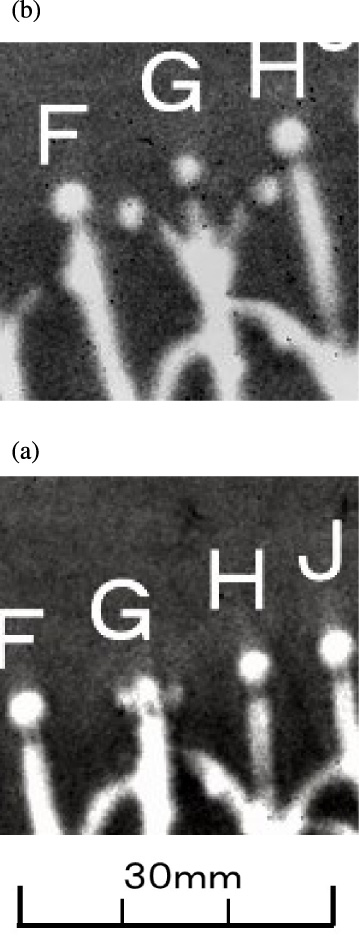
Magnified photographs of crack G.
From the above, it was presumed that there was a difference between the shadow spot which would be propagated as a trunk crack and that propagated as a branch crack. That is, there was a difference between the propagation energy of the trunk crack and branch crack immediately after divergence, and the propagation energy of branch crack was considerably smaller than that of the trunk crack in branching divergence.
Two divergence types of bifurcation and a branching, could be confirmed even with 10 mm thick tempered glass, as same with 3.5 mm thick tempered glass. Differences of the size of shadow spots generated by Caustics method were also observed in the two types of bifurcation and branching. It was inferred that the two cracks after the divergence had bifurcations based on the propagation energy values close to each other, since the similar sizes of shadow spots were observed at the bifurcation. On the other hand, the propagation energy of the branch crack immediately after divergence was estimated to be much smaller than that of the trunk crack, since the shadow spot formed on the branch crack was much smaller than that on the trunk crack and pre-divergence crack. Despite the small energy, the presence of energy that propagates in a different direction with the direction of trunk crack and pre-branch crack is important.
It was reported [12] that the divergence pattern of blood vessels was due to its diameter. Namely, bifurcation occurs when the diameter of blood vessels after divergence was almost the same, and branching occurs when the diameter of blood vessels after divergence was almost different. If the diameter of the blood vessel after divergence is similar, it would become a blood vessel that divides into two directions. When there was a large difference in the diameters of blood vessels, small blood vessels of small diameter divided from the trunk blood vessels. Expanding this concept into crack divergence, the bifurcation would occur when the propagation energies of the cracks immediately after the divergence had similar values, and the branching would occur when the propagation energies of the cracks immediately after the divergence had different values.
The observation result of this experimental shows that the divergence phenomena in tempered glass and that in blood vessels were similar. The difference in shadow size between the two divergence types which obtained by the Caustics method seems to correspond to the diameter of the blood vessel described by Oka [12]. It means that the divergence is not only caused by reaching a certain propagation energy, but also the difference in energy state at the divergence place creates the different divergence types.
Principal stresses 𝜎1 and 𝜎2 were determined by residual stress in tempered glass. It is also known that propagating crack in glass depends on “the normal stress law” [8]. Namely, the propagating crack propagates in a direction perpendicular to the large principal stress 𝜎1 (direction of 𝜎2). It was reported [18] that extremely high followability even when propagating in terminal velocity and the principal stress direction changes rapidly in center area of zone-tempered tempered. This means that the stress field is the one of the largest factors affecting crack propagating direction at critical or terminal velocities, such as fracture of tempered glass.
It was also reported [1,3] that the stress 𝜎
CR
formed by the propagating crack acts to add to the large principal stress in crack propagation of tempered glass. Considering this 𝜎
CR
, the crack propagation direction will be determined by the stress 𝜎 shown as below,
The model of bifurcation and branching is shown in Fig. 11. Figure 11(a) shows the case of a bifurcation, and Fig. 11(b) shows the case of a branching. Before the crack divergence, there was no big difference between the bifurcation and the branching as described above, the crack propagates based on the stress given by (𝜎1 + 𝜎 CR ). However, the stress field in tempered glass seems to be different at the location where the bifurcation occurs or the branching.
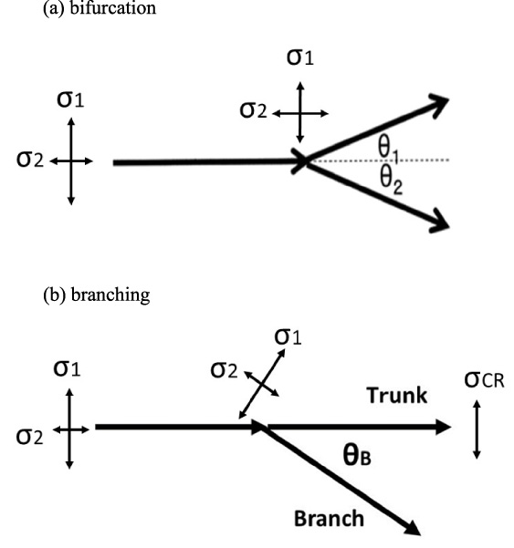
Stress fields at the crack divergence of bifurcation and branching.
Figure 11(a) shows that the force based on 𝜎2 equivalent to a repulsive force and the two cracks propagate in the separating direction. When a crack diverges, a repulsive force is indispensable to propagate for separating of two cracks. The principal stress 𝜎2, which acts perpendicularly to the principal stress 𝜎1 that has greatly affected the crack propagation before divergence, is essential for the repulsive force. This means that the repulsive force is generated at a place where the stress field 𝜎1 > 𝜎2 up to then changes to 𝜎2 > 𝜎1. It is assumed that the stress field given by 𝜎1 and 𝜎 CR has changed to the stress field given by 𝜎2 and 𝜎 CR at the divergence point generated bifurcation. After the crack divergence, the crack propagates straight based on 𝜎 CR .
Figure 11(a) shows that the case where the principal stress 𝜎1 exists at the divergence point in a direction different from the principal stress direction before divergence. At the divergence point under this condition, there is also a principal stress (𝜎1 > 𝜎2) whose direction is completely different from that before divergence, in addition to 𝜎 CR which is generated due to crack propagation before divergence. Since 𝜎 CR exists due to crack propagation before branching, the trunk crack propagates in the conventional direction even at the divergence point. On the other hand, a branch crack is generated and propagates based on the principal stress 𝜎1. Propagation energy is released by divergence based on the principal stress direction before divergence. It can be assumed that 𝜎 CR ≫ 𝜎1, considering the observation that the shadow of the branch crack was smaller than that of the trunk crack.
In case of branching, the large number of divergence phenomena were observed in which there were divergences in three directions of left side, center, and right side under a relatively short propagation distance. In general, crack divergence causes the propagation energy temporarily loss. For example, in the case of bifurcation, it was reported that the dynamic stress intensity factor decreased to about half [4]. Even in the case of branching, the reduction phenomenon of the propagation energy has also occurred, however, the energy loss is considered small because the change in the size of the shadow spot of the trunk crack was small. When the distance between two branch cracks was short, the divergence angle of the two branch cracks was close to 90°as shown in Fig. 9. This means of a high possibility that two step-divergence occurred at branching type. Namely, a branch crack based on the principal stress 𝜎1 diverged in first, immediately after that, the branch crack based on the principal stress 𝜎2 is diverged.
In this way, there will be a possibility of explaining the bifurcation and branching mechanism by combining a shadow spot information from the Caustics method and Eq. (1). In tempered glass, it can be assumed that the values of two principal stresses affect crack divergence. Namely, the bifurcation will occur at 𝜎1 ≒ 𝜎2, and branching will occur at 𝜎1 > 𝜎2. The crack divergence in tempered glass is likely to be affected by the stress field change at that divergence point. The results imply that crack divergence in tempered glass is close to “the concept as a means to release elastic energy after reaching the critical velocity” [9]. However, there are many unclear points about the relationship between elastic energy and crack divergence, since the shadows obtained by the Caustics method are not always clear, and quantitative analysis is difficult. Also, it is not easy to understand the stress field in tempered glass, and there is a problem in the reliability for the stress measurement. Regarding crack divergence in tempered glass, it is necessary to study it including detailed understanding of the stress field.
Since the shadow spot observed in this experimental was much ahead of the crack tip, it seems that the positional relationship between the shadow spot and the crack tip were different with conventional knowledge. Manogg [11] reported that there was a difference in the generation state of shadow spots depending on the material, for example, between resin and glass as shown in Fig. 12. The cracks in Fig. 12 have propagated from left to right in the figure. The dot line shows the case of resin, and positional relationship between the center of shadow spot and the crack tip almost coincided. On the other hand, in the case of the glass indicated by the alternate long and short dash line, the center of the shadow point occurs at a position ahead of the crack tip. It is not only glass that shadow spots are generated before the crack tip. Sakurada et al. [13] experimentally confirmed that the center position of PMMA was about 10.3% forward.
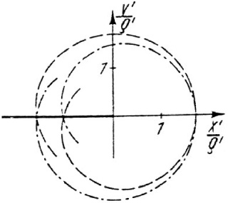
Position of shadow spots with propagating crack front.
The crack propagation in tempered glass is caused by the large tensile stress, and so propagates at a high velocity of about 1.500 × 10³ m/s which is near the terminal velocity. On the other hand, lots of experiments by Caustics method were measured by the double torsion method (DT method) or the double cantilever beam method (DCB method) that applies a load from the outside. The load applied to the crack tip in the plate thickness direction is thought different between the former and the latter. In the former case, the load in the plate thickness direction is not uniform but maximum in the center of the sample thickness, whereas in the latter case, it is almost uniform. Therefore, the stress state generated at the crack tip during propagation is thought different, and it has a possibility of being affected.
The authors reported that the existence of stress 𝜎 CR occurring at the propagating crack tip was suggested [3] and its value [13] for explaining the connecting phenomenon of cracks [18,19] observed in zone-tempered glass which is a kind of tempered glass. It was also reported that the stress field changed several millimeters ahead of the crack tip propagating in the zone-tempered glass. It is considered that this change in stress field occurs even in ordinary tempered glass at a similar or larger magnitude. This experimental observation of shadow spots being present in front of all the propagating cracks means that there is always a stress which changes the index of refraction distribution. It is speculated that the generation of shadow spots is closely related to the existence of stress 𝜎 CR , but the detailed examination seems to be a future research topic.
The crack divergence phenomenon in a 10 mm thick tempered glass was investigated using the shadow spots obtained by the Caustics method. As a result, the following findings were obtained: Two patterns of divergence which was bifurcation and branching, were also observed in the 10 mm thick tempered glass. In the case of bifurcation, the sizes of shadow spots generated at the two crack tips after divergence were similar. In the case of branching, a difference was observed in the size of shadow spots between the trunk crack and the branch crack, and the shadow spots on the branch cracks were much smaller than those on the trunk cracks. In tempered glass, it can be assumed that the values of two principal stresses affect crack divergence. Namely, the bifurcation will occur at 𝜎1 ≒ 𝜎2, and branching will occur at 𝜎1 > 𝜎2. From the above results, it is surmised that crack divergence in tempered glass is close to the concept based on energy release. However, the shadows obtained by the Caustics method are not always clear, and it is necessary to study them including a detailed investigation of the stress field.
Footnotes
Acknowledgements
The author is grateful to Professor Emeritus A. Toshimitsu Yokobori, Jr. of Tohoku University, Professor Emeritus Kiyoshi Takahashi, the late Mr. Haruo Komatsu and Mr. Toshio Mada of Kyushu University for making suggestions and performing the experiment, as well as to Central Glass Company Ltd. for providing glass specimens.
Conflict of interest
None to report.