
Abstract
In this paper, limiting the damage zone length in mode II during the interaction between a main crack and a surrounding dislocation in a brittle material is considered. This study is mainly based on the strain and stress field generated by varying the distance between the dislocation and a main crack by taking into consideration several cracks’ length.The proposed model is a dish element having an edge crack surrounded by an arbitrarily dislocation anduniformly loaded under the shearing mode II. The problem is then analyzed using Finite Element Method (FEM) along with the software ABAQUS. For each distance between the main crack and the dislocation, stress and strains fields are determined and then, the limiting length of damage zone is drawn. The results are compared with those found for the opening mode I.
Introduction
During the propagation of a crack, several researchers found that there are three zones in the vicinity of a crack tip [14,19,23,26]. The first zone is located at the end of the main crack, called “damage zone” being very difficult to study, because the strains and stress concentration is very high [15,18,20]. The following zone is known as a “singular zone” in which displacements and stress fields are continuous and infinite at the proximity of the crack tip. The third zone is very far from the crack tip, called “external zone”, in which the stress, strains and displacement fields can be determined, while respecting the boundary conditions. For the damage zone (DZ) with a very small size, researchers find that this area is difficult to determine by a classical elasticity approach [2,6,13]. Based on the theory of dislocations, Benzahar and Chabaat [12] limited the length of DZ as a function of the main crack’s length under the first mode of rupture (Mode I). In this present paper, a deep study is devoted to determining the length of DZ under a loading shear which corresponds to the second mode of rupture (Mode II). Numerically, the length of DZ can be obtained using the presence of a neighbouring dislocation at the crack tip. In this research work, we consider a dislocation that varies in the vicinity of a main crack. The model chosen is an element made of a brittle material with a rectangular shape (B = 700 mm, H = 500 mm and e = 2 mm). The element is initially cracked at one of its ends under a shearing load according to mode II. The model is discretized by finite elements in small squares and other triangular forms located at the end of the main crack. By applying a load that varies from 5 to 35 N/mm, for each crack length and distance between the dislocation and the main crack, plane strain and stress field (𝜀11, 𝜀12, S 11, S 12) are assessed all over the material. Based on these strain and stress fields, a length of DZ is determined function of the main crack’s length. Figure 1 represents the cracked model loaded in modes II.
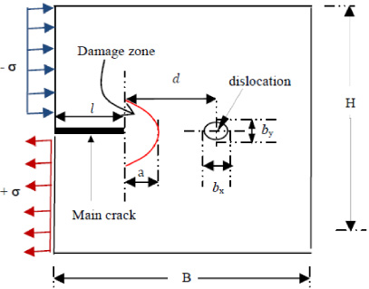
Fracture model under Mode II loadings.
Here, H and B are the width and length of the element, respectively. d is the distance between the main crack and the dislocation and l is the length of the macro crack. b x and b y are the dimensions of the dislocation along the x and y axis, respectively. +𝜎 and −𝜎 correspond to the tensile and compression loading applied according to the mode II.
The stress, strain and displacement fields can be characterized in the vicinity of a main crack [1,24]. In the case of a planar element with a thin thickness, the stress distribution is given by the following relation [3]:
The dislocation is a micro-crack having an infinitesimal size compared to the main crack [21]. It is easily detected by an electronic microscope device with a high resolution [5,8]. It is known that dislocations or defects can influence the main crack by reducing or amplifying the stresses generated during the crack dislocation interaction. Consequently, this phenomenon can accelerate or delay the crack propagation [10]. Generally, each micro-crack is endowed with an action force created by the movement of atoms and their interactions [4,25]. The displacement of a dislocation is determined by a Burgers vector noted by b
e
= b
x
+ b
y
[16]. In case of existing dislocation nearby a crack tip, the following complex analytical functions can be used:
An existing dislocation in the vicinity of a main crack can have an effect on the crack propagation. The interaction problem is formulated during the propagation of a main crack in the DZ [7,22]. The components of strain, stress and displacements of a dislocation near the main crack can be obtained using the theory of the complex potentials of Muskhelishvili [17]. Using a superposition of complex analytical functions, the interaction between the main crack and the dislocation is expressed by the following functions:
Using Eqs (2), (3) and (5), plane stresses generated during the interaction between the dislocation and the main crack are determined as follows [9]:
For the numerical study, a model of a rectangular element with a thin thickness and an edge crack is shown in Fig. 2. A dislocation of a circular shape having an infinitesimal size with respect to the macro crack size is considered. To proceed in this research work, several cracks’ length (l 1 = 50 mm, l 2 = 100 mm, l 3 = 150 mm, l 4 = 200 mm, l 5 = 250 mm, l 6 = 300 mm, l 7 = 350 mm) are taken in consideration. In order to find the stress and strains fields, for each crack length, one changes the position of the dislocation with a distance d. The numerical problem is then analyzed by FEM using ABAQUS where the cracked model is discretized by square and triangular elements. The chosen material has a Young’s modulus E = 70000 N/mm2 and a Poisson’s ratio 𝜐 = 0.20. The shearing fracture Mode II requires a loading parallel to the faces of the openings of the main crack.

Loaded model according to Mode II.
The chosen model is subjected to a shearing load that grows from 0 to 50 N/mm. By varying the dislocation’s position with respect to the main crack, the plane stress and strain are determined for each length of the main crack. On the other side, varying the length of the main crack, Figs 3 and 4a, b, c, d represent the plane stress and strain in case of a crack’s length of 50 mm and 350 mm subjected to a loading of 10 N/mm.
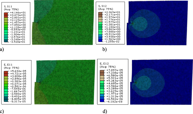
Stress and strain values for a short main crack (l = 50 mm). (a) S 11, (b) S 12, (c) 𝜀11, (d) 𝜀12.

Stress and strain values for a long main crack (l = 350 mm) (a) S 11, (b) S 12, (c) 𝜀11, (d) 𝜀12.
The values of the stress and strain can be positive and sometimes negative delimiting the zones between compression and tension. Applying a shearing load from 0 to 50 N/mm and then changing the dislocation’s position with respect to the main crack, values of stress and strain are obtained for each main crack’s length as illustrated in Figs 5, 6, 7 and 8. These figures represent the variation of strain and stress as a function of the distance of main crack dislocation for each main crack’s length.
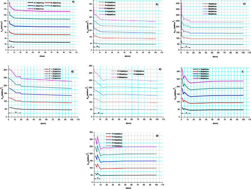
Variation of stress (S 11) versus the distance (d) between the main crack and the neighboring dislocation. (a) l = 50 mm, (b) l = 100 mm, (c) l = 150 mm, (d) l = 200 mm, (e) l = 250 mm, (f) l = 300 mm, (g) l = 350 mm.
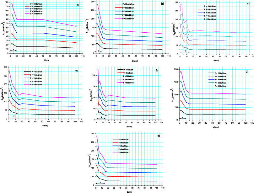
Variation of stress (S 12) versus the distance (d) between the main crack and the neighboring dislocation. (a) l = 50 mm, (b) l = 100 mm, (c) l = 150 mm, (d) l = 200 mm, (e) l = 250 mm, (f) l = 300 mm, (g) l = 350 mm.

Variation of strains (𝜀11) versus the distance (d) between the main crack and the neighboring dislocation. (a) l = 50 mm, (b) l = 100 mm, (c) l = 150 mm, (d) l = 200 mm, (e) l = 250 mm, (f) l = 300 mm, (g) l = 350 mm.
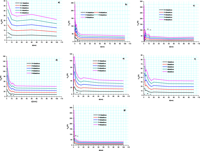
Variation of strains (𝜀12) versus the distance (d) between the main crack and the neighboring dislocation. (a) l = 50 mm, (b) l = 100 mm, (c) l = 150 mm, (d) l = 200 mm, (e) l = 250 mm, (f) l = 300 mm, (g) l = 350 mm.
In this research paper, the length of the DZ (a) is limited by the area whose stresses and strain increase sharply in the vicinity of the main crack. Strain and stress components generated during the main crack-dislocation interaction are represented in Figs 3 and 4.
In Figs 5 to 8, the main crack length varies from 50 mm to 350 mm while applied shearing load increases from 0 to 50 daN/cm. Taking in consideration the distance between the crack and a nearby dislocation (d), strain and stress components undergo change at the same rate. One can notice that value of s 11, s 12, 𝜀11 and 𝜀12 increases sharply in the vicinity of the main crack, which reflects that the dislocation has reached the DZ.
Figures 5 and 7 represent the variation of the plane stress and strain s 11 and 𝜀11, function of the distance (d), parallel to the applied load. It is seen that the stress field changes their speed from the distance d𝜖] 0,10] mm, d𝜖] 0,15] mm, d𝜖] 0,20] mm whose the length of the DZ a = 10 mm, a = 15 mm and a = 20 mm, respectively.
Figures 6 and 8 show the variation of S 12 and 𝜀12 function of the distance (d). Stress and strain components increase when the distance d𝜖] 0,10] mm and d𝜖] 0,15] mm whose the length of the DZ a = 10 mm and a = 15 mm, respectively.
For applying several shearing loads and varying the main crack’s length, the obtained lengths of the DZ are summarized in Table 1.
DZ length size for different main crack lengths
DZ length size for different main crack lengths
The percentage of length of the DZ relative to the main crack can be calculated by the following formula:
Whatever the loading applied in mode II for a given crack’s length, the ratio of the length of the DZ with respect to the main crack, calculated by Eq. (8), is shown in Fig. 9.
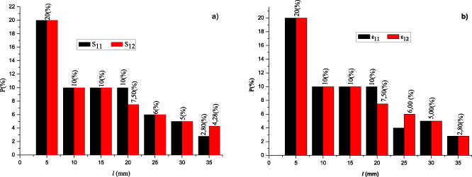
Percentage variation of the length of the DZ with respect to the main crack as a function of the generated stress and strain (a) stress, (b) strain.
One can notice in Fig. 9 that whatever the loading applied, the percentage P (%) is inversely reduced with the length of the main crack. In each stress and strain, the mean value of P (%) is given as follows: P m (S 11) = 9.11%, P m (S 12) = 8.96%, P m (𝜀11) = 8.82% and P m (𝜀12) = 8.75%. This percentage is very comparable with that found in mode I where P (%) = 8% (refer to [12]). Considering all stresses and strains (s 11, s 12, 𝜀11, 𝜀11), it is proven that whatever the length of the crack and the applied force, the percentage does not exceed twenty percent (20%).
The objective of this research is to determine the percentage of the length of the DZ compared to that of the main crack in mode II. Using different main crack lengths subjected to loadings according to mode II and taking in consideration the orientation of an existing dislocation in the vicinity of the main crack tip, stresses and deformations are found to be very high compared to the other places in the material. This small area is considered as a damage area. The stresses and deformation generated by the interaction between the main crack and the dislocation vary at the same rates depending on the main crack’s length, the distance between the crack and the dislocation and also on the applied loading. In mode II, the length of the DZ gets closer to nine percent (9%) of the length of the main crack which is almost comparable to that found in mode I [12] where the percentage is equal to eight percent (8%). It is obvious that the DZ maintains its size regardless of the type of loadings.
Footnotes
Conflict of interest
None to report.