
Abstract
BACKGROUND:
Structural integrity assessment of components containing cracks is of paramount importance when they are part of critical structures. In this context, the fracture behavior of components containing cracks is crucial.
OBJECTIVE:
To investigate the effect of the diameter, number and position of holes drilled in the vicinity of the centre crack in a finite plate on the mode I stress intensity factor (SIF).
METHODS:
A 2D model with central horizontal crack was created in ABAQUS® simulation software and validated with the analytical results after performing mesh convergence. Circular holes of different diameters and at different positions were then introduced in the vicinity of the crack.
RESULTS:
By increasing the diameter of the hole and its number, the SIF reduced significantly. An optimum amount of distance between the crack and the hole was found at which the SIF was minimum, beyond it increased and asymptotically approached that of the plate without holes.
CONCLUSION:
The diameter of the hole and the spcacing between the hole-centre and the crack axis has a major influence on the mode I SIF. By introducing multiple holes, the mode I SIF significantly reduced.
Introduction
The failure of many engineering structures are due to fatigue crack initiation and propagation. Hence, the identification of crack and arresting crack growth are very important for ensuring safe and reliable operation of the components. The structural integrity and residual life of components containing cracks are often evaluated by employing fracture mechanics. The severity of stress situation at the crack tip is quantified using fracture parameters like Stress Intensity Factor (SIF), J-integral and Crack Tip Opening Displacement (CTOD) [1,16]. Of the above, SIF is used for components subjected to linear elastic loads while J-integral and CTOD are used for plastic loads [4,9]. A crack when initiated in a component during its service requires to be repaired for extending the service life. Otherwise, the component fractures when the fracture parameter reaches its critical value [3]. It is therefore imperative to keep the magnitude of the fracture parameters well below the critical value for arresting the crack propagation and to prevent catastrophic failure [2,15].
Several techniques have been employed for arresting the crack propagation, all of which focuses on reducing the crack driving force, i.e., fracture parameters. To name a few, strip or patch repair method, stitching, indentation, artificial crack closure by crack filling, introducing residual stress, welding repair etc. [10,12]. Inducing compressive residual stresses around the hole (by applying pressure on its surface and upon removing the applied pressure) which resists the crack growth is one of the commonly used technique [5,13]. On introducing dimple at the crack tip by pressing hard steel balls, it was found to enhance the fatigue life the component by 220%, due to the residual compressive stress induced by the dimples [6]. The method of drilling stop holes is another technique to seize the crack growth. The crack tip blunts when it approaches the hole and thereby arresting the crack growth. Numerical simulation was carried out [11] by drilling two stop-holes at the tip of centre-crack and few multiple holes besides the stop-holes (ancillary holes) in a finite plate subjected to uniaxial load, to study the effect of these holes on the SIF. The results revealed that by increasing the diameter of the ancillary hole at a particular orientation (𝜃 = 0°), the fatigue life of the component was enhanced by nearly six times that of the base the component. Similar, analysis was performed in the case of a finite plate with double-edged crack by drilling two holes asymmetrically with reference to horizontal and vertical axes of the plate. The larger the horizontal distance between the crack and the hole, the more crack propagation was arrested [8]. Drilling of an additional hole near the crack to arrest its growth combined with pinhole interference is another technique. It is found that when an optimum diameter of additional hole placed at an appropriate position, reduces the crack driving force considerably [14]. The effect of collinear and parallel cracks on fracture strength and their interaction in an elastic solid is presented by Ichikawa, Ohashi and Yokobori [7]. It was found that the fracture strength always reduced in case of collinear cracks independently of loading type. While in the case of parallel cracks, the loading type affected the magnitude of the fracture strength. For the elastic solid under tension, anti-plane strain shear, the fracture strength increased. But under plane strain shear, it reduced the fracture strength.
In previous studies many attempts were made to understand the influence of stop-hole and additional drilled holes on the SIF. Accordingly, in this work, the investigation of the effect of multiple holes (not stop-holes) drilled along the vertical axis symmetrically about the centre crack in a finite plate on the mode I SIF is carried out. The effect of number of circular holes, its diameter and position from the centre crack introduced in a finite plate (along the vertical axis) on the stress intensity factor is analysed numerically in the context of arresting the crack propagation.
Finite element modelling
The present work considers a finite plate containing centre crack with circular holes introduced symmetrically on either side of the crack for the analysis.
Geometry: A two dimensional model of a finite plate with through the thickness centre crack subjected to uniaxial loading was developed in ABAQUS® simulation package. Due to negligible thickness relative to other dimensions, plane stress condition prevails in the plate. The geometry of the model and dimensional details are presented in Fig. 1 and Table 1 respectively. The results of plate with holes are then compared with the plate without holes (Fig. 2).
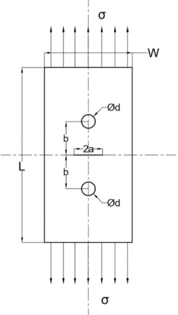
Geometry of the finite plate with centre crack and circular holes.
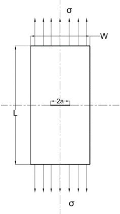
Standard geometry finite plate.
Geometry of the plate and load value
Constitutive model: The analysis was performed using a linear elastic and isotropic material. The material properties are Elastic modulus = 200 GPa and Poisson’s ratio = 0.3.
Element type: The domain was discretized with CPS4 (CPS4—Continuous stress/displacement Plane Stress 4 node bilinear element), which is well suited for elastic and small displacement problems [2]. To ensure small displacements, the crack-tip singularity is modelled using 8 node quad elements by collapsing one side (Fig. 3), so that one of the node moves to crack tip. By specifying quarter point mid-side node to merge with crack tip and selecting “Collapsed element, single side node”, in the software, square root singularity is ensured in the simulation. The meshed model with circular holes is shown in Fig. 4.
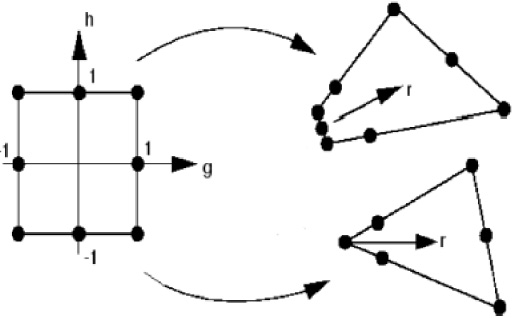
Collapsing of 8 sided second order quad element with centre crack without holes.

Meshed model with d = 2 mm and b = 10 mm.
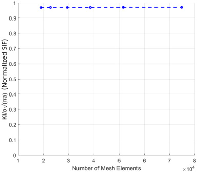
Mesh convergence plot.

Comparison of normalized Mode I SIFs obtained from Analytical equations and finite element modelling.

Effect of hole diameter on the Normalized Mode I SIF (K I/𝜎√(𝜋a)) located at constant distance (b = 10 mm).
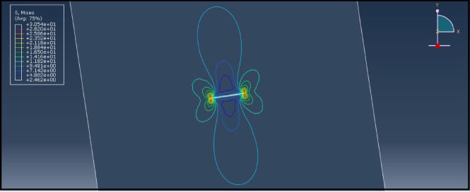
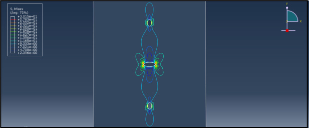
von Mises stress distribution around the crack without any hole.
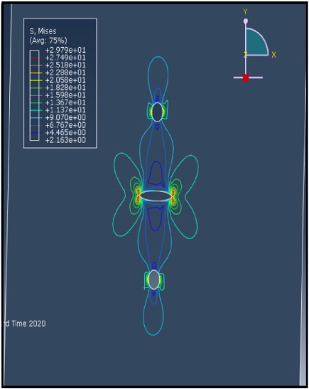
von Mises stress distribution for d = 2 mm and b = 10 mm.
Model validation: The finite element model without circular holes was first developed and validated against the standard model as presented in Ichikawa, Ohashi and Yokobori [7] for uniaxial loading conditions. The mode I stress intensity factor (KI) of a plate containing single centre horizontal crack is given by the following equation:
To ensure grid independency, the effect of number of elements on the normalized mode I SIF was monitored. As seen from Fig. 5, the normalized mode I SIF remains constant from 18000 elements to 75000 elements. In this analysis, 30000 elements were used to discretize the domain. To validate the model against the literature results, the mode I SIF was estimated for the current finite element model for different (a∕0. 5W) ratio and compared with analytical results as given by Tada, Paris and Irwin [17]. The deviation of the numerical results from the analytical one (Fig. 6) was under 2%, which shows that the model chosen is in good agreement with standard model. Further investigations are carried out using this validated model.
Effect of diameter of the hole
In the first step, the finite plate containing two circular holes situated symmetrically about the horizontal central crack is considered for studying the effect of diameter of the hole on the mode I SIF (as shown in Fig. 1). The influence of diameter of the hole on the mode I SIF with constant distance b (10 mm) is depicted in Fig. 7. As the diameter of the hole is increased, the SIF decreases in comparison to plate without any hole. To understand this trend, the stress distribution (von Mises) in all the cases of circular hole diameters were examined. In the case of finite plate with only centre crack, the maximum value of von Mises stress was 30.54 MPa with severe stress concentration around the crack, as shown in Fig. 8. As the hole diameter is increased from 2 mm to 10 mm as shown in Figs 9–13, the maximum value of the von Mises stress decreases as these holes reduces the stress concentration. In addition, the reducing stress concentration around the crack, SIF also decreases. The analysis can be further continued by increasing the hole diameter beyond 10 mm provided the boundaries of the plate do not interfere with the stress field around the hole and the integrity of the plate is not affected. However, further investigations are required to affirm this finding.
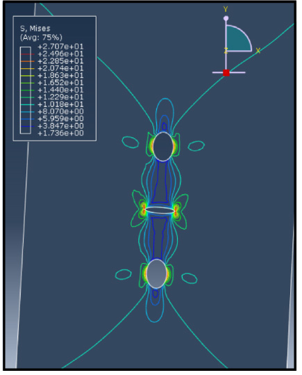
von Mises stress distribution for d = 4 mm and b = 10 mm.
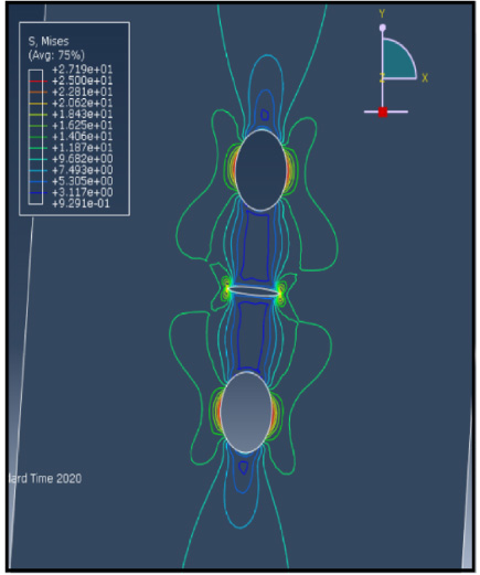
von Mises stress distribution for d = 6 mm and b = 10 mm.
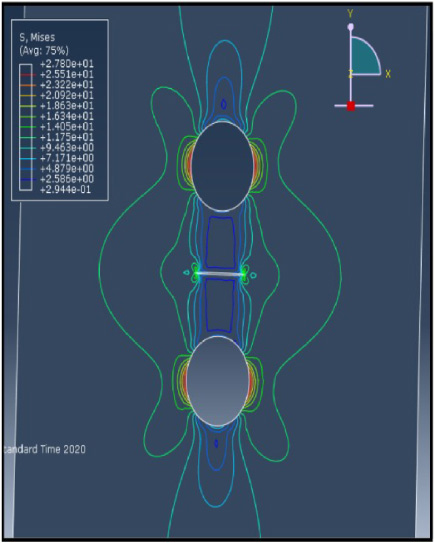
von Mises stress distribution for d = 8 mm and b = 10 mm.

von Mises stress distribution for d = 10 mm and b = 10 mm.
The influence of the distance between the centre of the hole and the crack on the mode I SIF for different diameters of hole is shown in Fig. 14. For the case of 2 mm diameter hole, as the distance b is increased, the SIF initially decreases up to certain value at a distance of around 5 mm and then increases up to 12 mm after which it asymptotically approaches that of a plate without hole. Similar trends were observed for larger hole diameters, as depicted in Fig. 14. This may be due to the non-interaction of the stress fields between the hole and the crack as the distance between them is increased (which is evident from Figs 15 and 16). That is, up to a certain distance b, there will be stress field interaction because of proximity of the holes. As it crosses some limit, the possibility of stress filed interaction becomes remote.
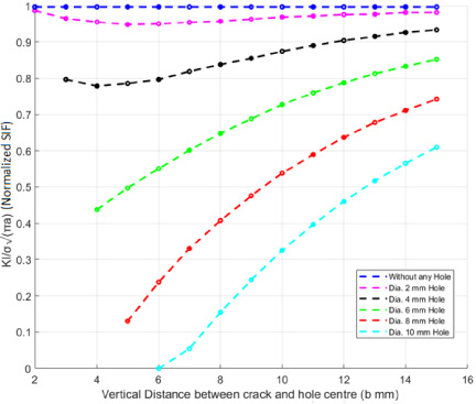
Plot of (K I/𝜎√(𝜋a)) Vs. Vertical distance (b mm) with different circular hole diameter (d mm).

von Mises stress distribution for b = 5 mm, d = 2 mm.
von Mises stress distribution for b = 15 mm, d = 2 mm.
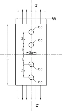
Geometry of finite plate with centre crack and multiple circular holes.
The configuration of finite plate with two holes symmetrically situated on either side of the crack with constant diameter and located at constant distance from the crack is shown in Fig. 17. The distance between the any two adjacent holes is 2b. Due to the limitation of plate dimensions, a maximum of ten holes were introduced in the plate. The effect of the number of holes and the distance b on the mode I SIF is shown in Fig. 18. By introducing ten holes spaced at 3 mm, around 30% reduction in SIF was observed in comparison to plate without any hole. While with respect to the case of a plate with two hole spaced at 3 mm, around 12% in SIF was observed. Thus, the introduction of multiple holes without affecting the integrity reduces the SIF of the plate.
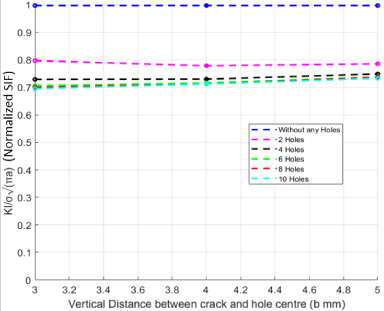
Plot of (K I/𝜎√(𝜋a)) vs. Vertical distance (b mm) for multiple circular holes of diameter (d = 4 mm).
The fracture analysis of a finite plate with horizontal central crack in the presence of multiple holes is performed in this work. Following are the conclusions drawn based on the results obtained:
As the diameter of the hole is increased, the maximum von Mises stress and the mode I SIF decreases significantly making smooth flow of stress lines around the crack. Further studies are required understand this observation. An optimum amount of spacing between the crack and the hole exists at which the mode I SIF is minimum, beyond which the SIF increases up to a certain distance and after that it asymptotically approaches that of a plate without hole. By introducing multiples holes symmetrically about the horizontal crack, the mode I SIF reduced significantly.
Footnotes
Conflict of interest
None to report.