
Abstract
Weld repairs of castings during manufacture is a well-known and acceptable practice if conducted in accordance with approved standards and procedures. However, either original casting induced cracks or cracking of these weld repairs in high temperature and aging plant is not uncommon. Structural integrity assessments of such components must not only consider reduced material toughness, due to temper embrittlement, but also the stress intensities generated during transient thermal events such as start/stops and quenching incidents. In the first of two case studies the acceptability of weld repair defects in a high pressure turbine outer casing is presented. Metallurgical assessments concluded significant temper embrittlement had occurred which was taken into account in a finite element based structural integrity assessment that considered design operating conditions as well as a hypothetical quenching event. Low pressure turbine bypass valves are considered in the second case study. In this case the material temper embrittlement was found not to be as severe but the criticality of pre-warming to reduce transient thermal stress and by extension crack stress intensities during trips or shutdowns was clearly demonstrated. Remaining life assessments concluded the defects to be acceptable for operation to the next planned outage.
Introduction
Weld repair of large cast components such as steam turbine casings (Fig. 1) and valve casings is a common practice that is acceptable, within limits as agreed between the supplier and the user, provided it is conducted in accordance with qualified welding procedures and quality is controlled. However, it is also common to detect large casting or welding induced defects in later life, often in these weld repaired areas.
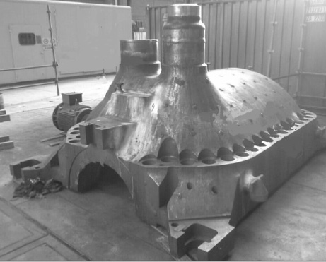
Top half casing showing two inlets with replaced right-hand side steam penetration.
This may be, in part, due to the higher sensitivity of current non-destructive-testing (NDT) techniques or the fact that these manufacturing flaws were subsurface, and not detected initially, and have broken through the surface due to normal (or out of normal) operating conditions. When such a defect is detected the user has primarily four options each with its own advantages, dis-advantages and requirements. These options are replacement, repair, excavation or qualification by fitness-for-service (FFS) assessment. Two case studies illustrating the last option are presented. In addition to normal transient and steady state loading a hypothetical quenching incident is also investigated. Time dependent stress intensity responses were calculated by finite element analysis using Ansys 17.1.

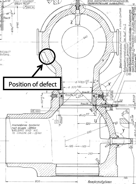
Position and surface extent of internal defect near the right-hand side steam inlet. Note partial excavation of defect.
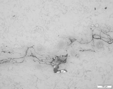
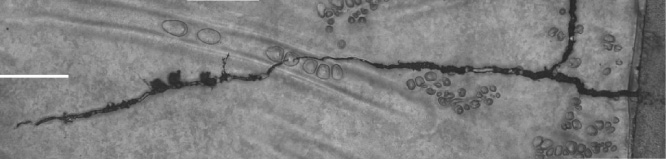
Photomicrograph showing the crack tip of the internal crack. [200× Magnification, 5% Nital Etch].
Background
Inspection of the high pressure (HP) turbine outer casing of a 618 MW power generation unit (Fig. 1) by magnetic particle inspection (MT) during a planned general overhaul detected two defects. These defects were found to have been related to original casting processes and weld repairs of the turbine casing. It is suspected that these manufacturing defects were subsurface, and thus not detectable by surface inspection, but broke through with operation. Due to energy supply capacity constraints at the time the unit was required to return to service with the defects provided it could be demonstrated that it would be safe to operate albeit for a reduced inspection interval.
Design and operating conditions
The 1980’s vintage casing was manufactured from GS17CrMoV5-11 (CrMoV). At the time of the discovery of the defects the unit had accumulated a total of 212 kh and 328 starts. Nominal operating pressure and temperature of the casing is 4.3 MPa and 330 to 430 °C. The casing top (Fig. 1) and bottom halves are bolted together and have two inlets on both sides. The minimum specification for the material Charpy impact energy at room temperature is nominally between 24 and 27 J [1]. However, embrittlement of these components is known to occur over time as a result of elevated operating temperatures where impurities migrate to grain boundaries. Material samples were cut from the front of the casing for Charpy impact testing. Three samples were tested at 230 °C (upper shelf) and one at room temperature. The average impact energy at 230 °C was found to be 95 J. From the room temperature result (7 J) it can be concluded that temper embrittlement likely occurred. These measured values are similar to what was found in other cases of post service casings e.g. [3].
Defect descriptions
The first defect was found on the inner surface of the casing at the right-hand steam inlet (Fig. 2). The defect was oriented in the longitudinal direction w.r.t. admission line. Phased array ultrasonic testing (PAUT) was performed and the maximum depth was found to be 49 mm with a total length of 120 mm. The internal area was etched where the defect was located and a previous weld repaired area was found. The wall thickness in this area was reported to be 114 mm and the remaining ligament was reported to be clear of subsurface defects. Metallographic replication indicated that the top part of the crack in Fig. 2 ran through a weld repaired area while the bottom part of the crack ran in casting parent material. The crack in the parent material was interpreted to be a solidification defect as indicated by decarburization around a defect with multiple intergranular facets especially at the crack tip where the crack was partially removed by localized grinding (Fig. 3). No signs of crack growth were observed at the crack tips. It was postulated that the crack a subsurface manufacturing defect (solidification and weld repair cracking) not detected by NDT during and after the weld repair. Only the small remaining ligament between the defect and the surface broke through with operation to make it detectable by MT during the outage.
PAUT was performed on the external defect to determine the depth, direction and orientation and to assess the remaining ligament below and around the crack for subsurface defects. The external defect consisted of two regions; one on top of the casing protrusion nominally in the horisontal direction and the other running along the vertical side of the casing protrusion with a total length of 200 mm (Fig. 4). The crack in the vertical region was found to be intermittent with a depth of approximately 78 mm. The remaining wall thickness below the vertical region was measured as 26 mm and no signs of other defects were observed in this area. The horisontal defect depth was measured to be 63 mm with a remaining wall thickness of 45 mm. No other indications were detected in the remaining ligament. Metallographic replication indicated that this crack was associated with a weld repair and areas of multiple intergranular microcracking along the weldment (Fig. 5). It was postulated that the defect is reheat/stress relief cracking associated with the weld repair and no conclusive sign of crack growth was found at the crack tip and in areas of micro damage. Similar to the internal crack it was probably subsurface manufacturing defects (weld repair stress relief and reheat cracking) not detected by NDT after the weld repair. Only the small remaining ligament between the defect and the surface broke through with operation to make it detectable by MT during the outage.
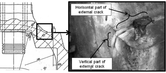
Position and surface extent of external defect with partial excavation.
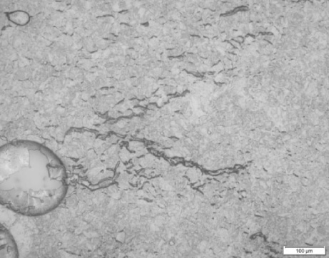
Photomicrograph showing stress relief damage in an area away from the main crack (200× Magnification, 5% Nital etch).
A 3D finite element model of the top casing was developed using commercial software Ansys 17.1. Material parameters used in the analysis are summarised in Table 1. The internal and external defects were modeled directly into the 3D model using the pre-meshed crack functionality in Ansys. Direct FE modelling of a ∼200 × 80 mm crack in the vertical direction at the external position resulted in a stress intensity of ∼5.6 MPa
GS17CrMoV510 (1.7706) mechanical and physical properties
GS17CrMoV510 (1.7706) mechanical and physical properties
1. Determined from measured Charpy impact results using correlations.
A FE based plastic collapse analysis was conducted to determine the reference stress in the remaining ligaments below the internal and external defects modelled directly in Ansys. Plastic collapse analysis was conducted using an elastic-perfect-plastic material model and by increasing the internal pressure until ‘rupture’. Plastic collapse did not occur at either of the defects but in the top cylindrical section of the casing. The reference stress was calculated to be 40.5 MPa. The nominal equivalent stress below the defects will thus be lower than this value. The yield strength of the material at an operating temperature of 430 °C is 326 MPa [1]. Using this value as the flow strength (conservative approach) the load parameter (Lr) can be calculated as 0.12 which is below the Level 1 required value of 0.8 as per BS 7910:2013 [2].
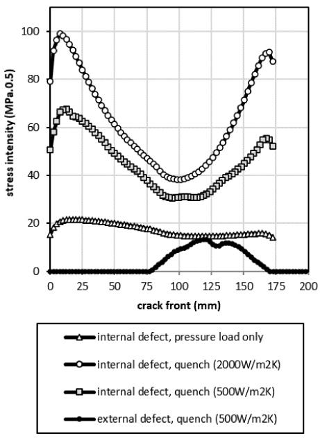
Peak calculated stress intensities along crack fronts (from surface to surface) for steady state and quenching cases.
A leak before-break assessment aims to demonstrate that a crack in a component will remain stable if it propagates through wall, i.e., a leak will occur and not a brittle fracture. The condition of leak before break was demonstrated by showing stability for a through wall crack with a length of at least twice the wall thickness (i.e. 200 mm long through wall). Applied stress intensities for the two defect positions were calculated as 23 and 39 MPa
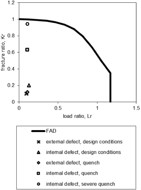
Level 2 failure assessment diagram (FAD).
Quenching of the HP outer casing can occur under certain conditions during start-up. During extended periods of full speed no load conditions the HP outer casing will reach a uniform temperature of 400 to 430 °C. When the turbine is then synchronised and loaded manually at faster than normal ramp rates the HP turbine exhaust temperature can drop suddenly by up to 200 °C. This type of incident can be avoided by careful manual run-up or run-up in full auto mode. A quench of this magnitude was none the less investigated as it cannot be completely discounted. A transient thermal static structural analysis was conducted to determine the peak stress intensity for the internal crack. An initial uniform temperature of 430 °C was assumed followed by a sudden convection heat transfer with a bulk temperature of 230 °C applied to the internal surfaces. It was assumed that the steam temperature will decrease by 200 °C (to 230 °C) in 60 s.
Convection heat transfer coefficients in steam turbines for dry steam conditions can range from 50 to 5000 W/(m2⋅K) [9] depending on the steam pressure, temperature and velocity as well as the casing geometry and wall temperature, amongst others. Although a heat transfer coefficient of ∼100 W/m2⋅K was calculated based on [6] a value of 500 W∖(m2⋅K) was applied. An additional case using a convection heat transfer coefficient of 2000 W∖(m2⋅K) was also calculated. As a result of the stress gradient (highest stress on the internal surface) the stress intensity at the tips of the internal and centre of the external defects tend to increase proportionally more than the rest of the crack front (Fig. 6). The peak stress intensity reached during the quenching incident assuming a coefficient of 500 W∖(m2.K) is 13 and 67 MPa.
Low pressure turbine bypass valve
Background
Surface inspection by MT of a low pressure (LP) turbine bypass valve of a 686 MW power generation unit detected a 67 mm long surface breaking defect just below the valve insert attachment face (Fig. 8). Further analysis indicated the defect to be a manufacturing defect related to a weld repair. In order to allow for proper planning and preparation for a weld repair the acceptability to operate with the defect as is for a limited duration was investigated.

Position and surface length of defect.
Replica micrograph of the manufacturing induced macro crack.
Position of the defect in the bypass valve casing.
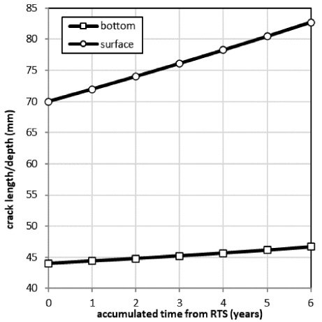
Calculated creep crack evolution over a 6 year period.
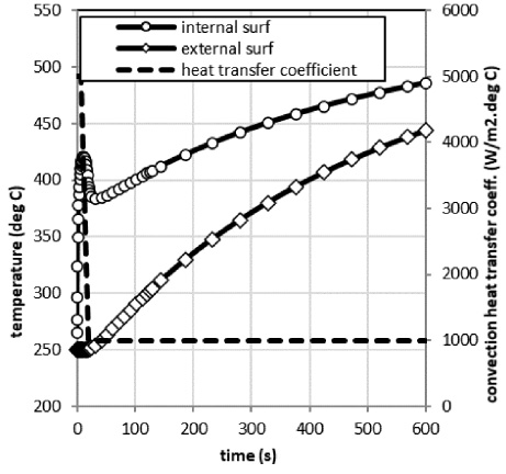
Temperature increase for 1st 10 minutes after shutdown.

Stress intensity response for a unit shutdown with crack extent as calculated for 6 years of operation.
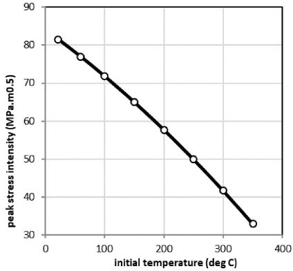
Effect of an increasing pre-warming temperature on the peak transient stress intensity during unit shutdowns/trips.

Stress intensity response for a hypothetical quenching incident.
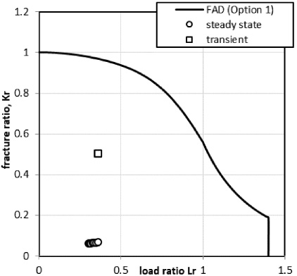
Failure assessment diagram showing assessment point for both steady state and transient operating conditions.
The LP bypass valve operates only during start-ups and shutdowns at an internal pressure of 4 MPa and a temperature of 535 °C. When the unit is on-load the valve is kept at an elevated temperature of approximately 250 °C by a warming line. The power generation unit has operated for a total of 189 kh and has accumulated 30 cold starts and 125 hot starts. This defect was not detected or reported during a previous inspection, however, it is likely that this weld defect existed at the time but was sub-surface and hence not detectable by surface inspection. Further operation and transient cycles are expected to have caused the defect to ‘break through’ to the surface. The material of manufacture is GS17CrMoV5-11 (1.7706). Three Charpy impact samples were cut from the valve casing and tested at room temperature to find mean impact energy of 62 J. However, as a conservative approach the minimum tested value of 46 J was used in calculations. This correlates to a lower shelf material toughness of ∼99 MPa
Defect description
An external MT inspection was conducted and a 67 mm long surface breaking defect was identified just below the valve insert attachment face (Fig. 8). PAUT inspection was conducted and the depth of the defect was found to be 44 mm. Wall thickness in the area of the defect was found to be 64.8 mm. This correlates well with the original design dimension of 60 mm in this area. Evaluation of material replicas indicates the defect to be a manufacturing macro crack in a weld repair area with no signs of active creep crack propagation (Fig. 9). The macro crack was oxide filled, surrounded by micro cracks and stress relief voids.
Fit-for-service assessment
No evidence of active in-service creep crack propagation could be found during the evaluation of the material replicas. It was nonetheless assumed that creep crack propagation will ensue as soon as the valve casing is put in service. As a conservative approach it is also assumed that the valve stays in service during unit steady state operation. The defect is positioned in an area in the casing that can be simplified as a sphere (Fig. 10). Nominal stress in this position was calculated to be ∼23 MPa. Creep reference stress for the component with a crack was calculated using the remaining ligament thickness below the crack as the wall thickness (e.g. creep reference stress is 82 MPa for a 44 mm deep crack). Stress intensities for a thumbnail crack were calculated finite element analysis using the ‘arbitrary’ crack object in Ansys 17-1. Stress intensity at the two end-points of the crack on the surface was found to be higher than at the deepest point. This suggests that if creep crack propagation was active the crack will grow faster in the length direction than in the depth direction. Creep crack propagation rates were calculated using simplified formulations in [2, equation S.5 in] which is based on the stress intensity, the reference stress and the creep rupture time at the reference stress. Iterative calculations and FEA were conducted to estimate the creep crack evolution over a period of 6 years, assuming a load factor of 100% (Fig. 11). The stress intensities and reference stress after 6 year of operation were calculated to be lower than the material toughness and proof strength. As such no brittle fracture or overload failure during normal steady state operation is expected.
Transient thermal analyses were conducted to consider the structural integrity of the valve casing during shutdown/trip conditions as well as for a hypothetical thermal quenching incident. Convection heat transfer coefficients were based on measured results reported in [9]. Initial transfer coefficients can be very high when the casing metal temperature is below the saturation temperature of the steam. For a steam pressure of 4 MPa the saturation temperature is 250 °C, the pre-heating temperature. A convection heat transfer coefficient of 5000 W/m2 ⋅°C was assumed for the first 20 s after which a value of 1000 W/m2 ⋅°C was assumed. No heat transfer was assumed from the external surface i.e. perfectly insulated. The internal and external temperature increase for the 1st 600 s is shown in Fig. 12 and the stress intensity response for the crack dimensions calculated to exist after 6 years of operation (i.e. ∼83 mm long and 47 mm deep) is shown in Fig. 13. Note that the peak transient stress intensity is significantly higher than the steady state stress intensity. However, it is still well below the material room temperature toughness which implies that brittle fracture is not expected for shutdowns/trips with the postulated crack size after 6 years of operation, provided the valve temperature is maintained at 250 °C or higher during steady state operation. The effect of varying initial temperatures (i.e. pre-warming temperature) on the peak transient stress intensity is shown in Fig. 14. Note that for an initial temperature of 22 °C the peak transient stress intensity is 82 MPa
A hypothetical quenching incident was simulated assuming a valve temperature at 535 °C, a steam temperature of 200 °C and a convection heat transfer coefficient of 1000 W/m2 °C. The calculated peak transient stress intensity for the described hypothetical quenching incident was found to be low and is not expected to pose a risk of brittle fracture. Note that the highest stress intensity in this case occurs at the bottom of the crack (Fig. 15).
Fatigue crack propagation due to start/stops are possible considering the values of stress intensities. However, the number of these cycles is very low and fatigue crack propagation is considered to be negligible for the conditions considered over a period of 6 years.
A failure assessment diagram in accordance with [2] confirms that no brittle fracture or plastic collapse is expected for steady state operation or transient operating conditions (i.e. shutdown/trip) for a period of at least 6 years (Fig. 16).
Conclusions
Two case studies where fitness-for-service assessments were used to demonstrate the acceptability of operating for limited durations with original manufacturing (casting or weld repair induced) defects in castings were presented. The reliability of such assessments depends heavily on non-destructive-testing to properly characterise the flaws and check the soundness of the remaining ligament as well as metallurgical analysis to confirm the damage mechanism and state of the material. Careful consideration of the loading conditions experienced is required and adequate margins of safety, depending on level of confidence of input parameters, must be applied. Realistic worst case out of normal conditions e.g. quenching should also be assed. In the two cases presented acceptability for limited further operation was demonstrated successfully on a failure assessment diagram considering both fast fracture and plastic collapse.
Footnotes
Acknowledgements
The authors wish to acknowledge inputs from Mr. Philip van der Meer and Me Felicia Ramela for assistance with the metallurgical analyses. Eskom is thanked for the opportunity to report and present this work.
Conflict of interest
None to report.