
Abstract
Blowout preventer reliability is important for safe drilling operation. In order to study the sealing mechanism and failure mechanism of conical blowout preventer, a numerical model of conical blowout preventer was established based on the theory of large deformation of rubber, and the deformation law, stress distribution and sealing performance of rubber core in well shut-in operation were studied. The results show that there are stress concentrations in the contact area between the rubber core and the piston, the grooves in the middle of the adjacent support ribs, and the chamfered corner of the inner wall of the rubber core, the main form of failure at these locations is rubber cracking. Higher stress is present in the neck region of the upper plate and the back region of the lower plate of the support ribs. The inner wall surface of the rubber core gradually produces stripes of wrinkles, and the smaller the size of the sealed drill pipe, the more obvious the wrinkles are. When the drill pipe joint is sealed by the rubber core, there is a sealing buffer zone at the shoulder, and the contact pressure change abruptly. The lower portion of the rubber core’s inner wall serves as the primary sealing area. Increasing the piston displacement appropriately can enhance the sealing performance of the rubber core. The results can provide a theoretical basis for the optimization design of the conical blowout preventer.
Introduction
In oil and gas exploration and development, once the formation fluid is out of control, it will lead to blowout accidents, resulting in catastrophic consequences [14]. The annular blowout preventer is one of the most important devices in well control equipment, which can effectively control the internal pressure of oil and gas wells and prevent blowout accidents [17]. The rubber core is the most important component of the blowout preventer to achieve sealing, which is vulcanized by rubber matrix and support ribs. Therefore, it is of great significance to study the sealing performance and failure mechanism of the rubber core to improve the safety of drilling operation and extend the life of the rubber core.
Many scholars have carried out research work on annular blowout preventers. For example, Gu et al. [4] developed the FHZ28-105 annular blowout preventer rubber core, and analyzed the sealing performance and failure location of the rubber core through experiments and simulations. Deng et al. [2] established a finite element model of the rubber core sealing drill pipe, analyzed the main reasons for the failure of the rubber core, and optimized the height of the inner cylinder of the rubber core. Xu et al. [18,19] carried out mechanical experiments on spherical rubber core materials, studied the data processing methods of the rubber intrinsic structure model, and summarized the main failure forms of rubber cores. Li [23] studied the force and deformation law of the rubber core under several typical working conditions, and summarized the common failure forms of the rubber core. He et al. [6] established a finite element model of drill pipe sealed with rubber core, and analysed the factors affecting the fatigue life of rubber core. She et al. [13] combined the advantages of Shaffer and Hydril annular blowout preventers to design a claw type spherical rubber core, which has the characteristics of reliable sealing, long service life and easy disassembly and assembly. Based on the theory of rubber large deformation and the sealing mechanism of rubber core, Dong et al. [3] established a finite element model of rubber core sealing drill pipe joint, and proposed a small-angle, long-shoulder joint structure. Wu et al. [16] optimized and analyzed the stress concentration area of the rubber core to obtain the optimal structural parameters. Liu [7] established a finite element model for dynamic sealing of the rubber core of the rotating blowout preventer, optimized the rubber core structure, and obtained the best rubber hardness. Guo et al. [5] established a finite element model of dynamic sealing of the rubber core of the rotating BOP, studied the sealing performance of the rubber core, and obtained the optimal combination of the structural parameters of the rubber core. Zhang et al. [22] established a numerical model of dynamic sealing of spherical blowout preventers to explore the stress distribution and failure modes of the rubber core during the well sealing and drilling processes. Wang et al. [15] proposed a research method based on uniaxial compression experiments to address the constitutive modeling problem of anti-spray rubber core, which is used to determine a reasonable rubber constitutive model. Liu et al. [9] established a numerical model of the full-size spherical blowout preventer and proposed a structural optimization design scheme for the spherical rubber core.
At present, the majority of researchers’ studies primarily focus on the spherical core within annular preventers, with less research conducted on the deformation patterns, stress–strain behavior, and sealing performance of conical rubber core annular preventers during the well sealing process. Therefore, based on the theory of large rubber deformation, a full-scale numerical model for conical blowout preventer was established, the mechanical behavior and sealing performance of the rubber core during the well-sealing process were investigated. It is of great significance for optimizing design of conical blowout preventer and ensuring the safety and stability of operational process.
Conical blowout preventer model
Working principle
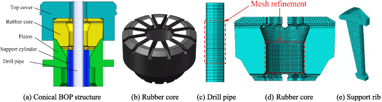
As shown in Fig. 1, the conical blowout preventer is mainly composed of top cover, rubber core, piston, support cylinder and other components. When sealing the well, the hydraulic oil enters from the closed oil chamber, pushes the piston upward movement, under the restriction of the top cover, the rubber core deforms and shrinks to the center, the support ribs move closer to each other, and the extruded rubber fills the annular space between the rubber core and the drill pipe, and finally sealing the wellhead. When the well is opened, the hydraulic oil enters from the opening oil chamber, pushes the piston downward movement, the piston extrusion force on the rubber core is relieved, the rubber core returns to its original state under the action of its own elasticity, and finally opening the wellhead.
Geometric model and finite element model.
In order to accurately describe the hyperelasticity of rubber materials, it is necessary to establish a suitable form of strain energy density function. There are two main forms of strain energy density function for rubber materials under isotropy conditions:
The relationship between I
i
and 𝜆
i
is:
The strain energy density of isotropic materials can be decomposed into partial strain energy density and volumetric strain energy density in the following form:
Let
The reduced polynomial model is a special expression of the complete polynomial model, let all C
ij
= 0(j ≠ 0) obtain the reduced polynomial model:
(1) Mooney–Rivlin model [10]
For a complete polynomial, when N = 1, the Mooney–Rivlin model is obtained as:
(2) Neo-Hookean model
For reduced polynomials, when N = 1, the Neo-Hookean model is obtained as:
(3) Yeoh model [21]
When N = 3, J = 1, the Yeoh model is obtained as:
(4) Ogden model [11]
Yeoh model is more suitable to simulate large deformation process of rubber filled with carbon black [12,20]. Due to the significant overall deformation of the rubber core during the well-sealing process, the Yeoh model for simulation is selected.
The rubber core has material nonlinearity, geometric nonlinearity and boundary condition nonlinearity during the sealing process [1]. Due to the complexity of simulating the sealing process, the following assumptions are made for the model:
(1) The rubber core material and the parts of the blowout preventer are isotropic.
(2) During the blowout preventer well-sealing process, the piston maintains a constant speed movement, ignoring the influence of hydraulic oil and drilling fluid on the rubber core.
(3) Ignoring the influence of external environmental factors such as temperature and fluid medium during the sealing process of the blowout preventer.
Analytical model of conical BOP
The conical BOP structure is shown in Fig. 1(a), the support ribs are evenly distributed in the rubber core and vulcanized with the rubber. The Yeoh constitutive model [8] was used to simulate the mechanical behavior of rubber materials, C 10 = 3.777 MPa, C 20 = −4.696 MPa, C 30 = 7.093 MPa, the density was 1500 kg/m3. The top cover, support ribs, piston, drill pipe and support cylinder are all elastoplastic materials, with an elastic modulus E = 210 GPa, Poisson’s ratio 𝜇 = 0.3, and a density of 7800 kg/m3. A load of 220 mm along axial displacement is applied to the piston.
The top cover, drill pipe, support cylinder and piston are meshed with hexahedral elements. The rubber core and support ribs are meshed using tetrahedral elements. The mesh in the sealing regions of the rubber core and drill pipe is refined, as shown in Fig. 1(c), (d).
Working condition of rubber core sealing the drill pipe
During the well sealing process, the sealing performance of the rubber core is mainly affected by the dynamic load, fluid medium and ambient temperature. Dynamic loads lead to areas of high stress inside and on the rubber surface, where is prone to crack. With the opening and closing of the well, the cracks gradually expand and eventually cause the rubber core to fail due to extensive damage. The fluid medium produces physical swelling and chemical corrosion to the rubber core, causing the rubber material to age, weakening its mechanical properties and shortening the service life of the rubber core. When the ambient temperature is high, the rubber material will soften and structural failure, resulting in a decrease in mechanical properties. When the ambient temperature is low, the rubber material will appear glassy, which is hard and brittle, and loses its original elastic characteristics.
Mechanical behavior of the rubber core
Deformation of the rubber core
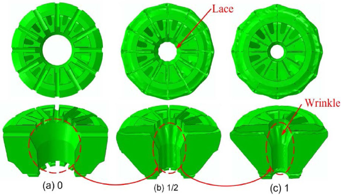
Figure 2 shows generation process of surface wrinkles on the inner wall of the rubber core. The deformation of the rubber core is uniform before the 1/2 process, then a uniform lace shape is produced on the inner surface of the rubber core in the 1/2 process. As the rubber is continuously extruded, the lace-like projections are self-contacted to produce wrinkles. The rubber in the wrinkled area is in a compressed state, while between two adjacent wrinkles, the rubber protrudes toward the center in a stretched state. As the well sealing process proceeds, the rubber core wrinkles become more and more obvious.
Generation process of surface wrinkles on the inner wall of the rubber core.
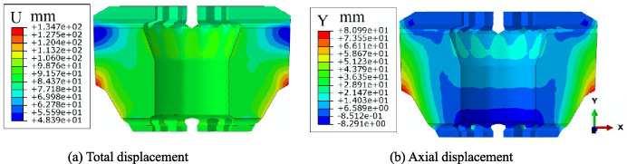
Figure 3 shows the displacement contour of rubber core. In Fig. 3(a), the displacement on the inner wall of the rubber core is relatively uniform. The corner and conical surface of the outer wall of the rubber core have larger displacement, which is prone to fatigue damage. The upper end of the outer wall of the rubber core is less displaced, because the rubber in this area is squeezed upward during the sealing process of the rubber core, causing it to move away from the direction of the centerline. In Fig. 3(b), the displacement of the rubber core gradually decreases from the outside to the inside. The displacement at the corner of the outer wall of the rubber core is the largest, which is due to the friction exerted on the rubber by the piston’s conical surface, resulting in a large axial displacement. Since the axial displacement of the upper end of the inner wall of the rubber core is positive and the axial displacement of the lower end is negative, the inner wall of the rubber core is stretched axially.
Displacement contour of rubber core.
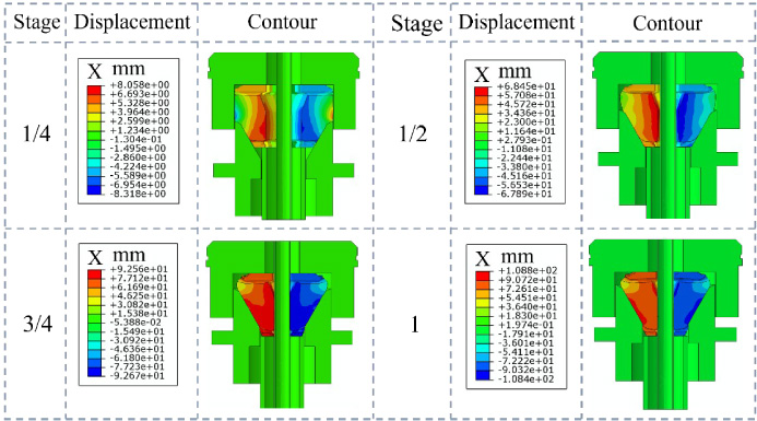
Figure 4 shows the radial displacement contour of the rubber core at different stages. In the well-sealing process, the maximum radial displacement of the rubber core is 108 mm. The displacement gradually increased from top to bottom, among which the displacement of the rubber core near the lower part of the support rib is the largest, indicating that the rubber at the lower end of the inner wall of the rubber core is deforming downward, so more rubber is extruded in the cylindrical area of the inner wall of the rubber core. At the 1/2 process, the lower end of the rubber core approaches the lower end of the piston’s conical surface. At the 3/4 process, the rubber core has been completely in contact with the drill pipe, and the lower end of the rubber core slides to the piston’s inner cavity. After the lower space of the inner wall of the rubber core is filled with rubber, the subsequently extruded rubber fills the upper space of the rubber core in the axial direction, and finally forms a funnel-shaped at the upper end.
Radial displacement contour of the rubber core at different stages.
Figure 5 shows the strain distribution of the rubber core during the well-sealing process. On the whole, the area of contact between the rubber core and the piston exhibits higher strains, with the greatest strains occurring around the lower end of the support ribs. At the 1/4 stage, clear striped strains emerge on the inner wall of the rubber core, aligning with the subsequent appearance of wrinkles. At the 1/2 stage, the ravine between the support ribs is a low-strain area, and 12 locally larger strain areas appear on the conical surface of the outer wall of the rubber core. These areas correspond to the number of support ribs and are evenly arranged along the circumference, indicating significant deformation of the rubber around the support ribs. At stage 3/4, the chamfer strain of the ravines between the support ribs and the inner wall of the rubber core continues to rise, and the strain value is close to the contact area between the piston and the rubber core. At the end of the well-sealing process, the upper chamfered section of the inner wall of the rubber core exhibits higher strains, coinciding with the location of the rubber core’s cracking.
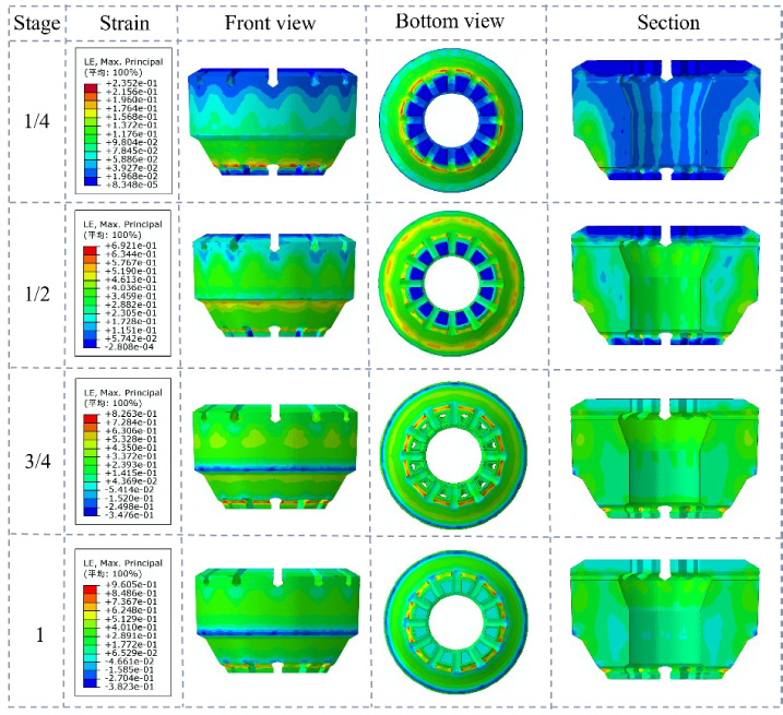
Strain distribution of the rubber core during the well-sealing process.
Figure 6 shows the stress distribution of the rubber core after the well is sealed. The area of stress concentration corresponds with the failure position of the rubber core in actual working conditions. In Fig. 6(a), because the rubber at the wrinkles is compressed, and the rubber between the adjacent two folds is stretched. At the chamfer of the inner wall of the rubber core, the stress is distributed along the circumferential array, and the stress in this part extends down the inner wall to the chamfer. As a result, during repeated well-sealing operations, cracking will appear on the upper surface of the inner wall of the rubber core. In Fig. 6(b), there are two main reasons for the rupture of the rubber at the bottom of the rubber core, the first reason is that the inner wall of the piston is conical in shape, and the bearing area is limited, the lower part of the rubber core is gradually extruded below the bearing surface of the piston when extruded to the center, then the corner of the inner cavity of the piston cylinder and the cone surface further squeezes the rubber core. The second reason involves a sudden change in material properties at the contact region between the lower end of the outer wall of the rubber core and the piston, which produces obvious stress concentration during compression. It is easy to cause rubber rupture at the bottom of the rubber core under the coupling of these two unfavorable factors. The lower end of the inner wall of the rubber core serves as the main sealing area, and the degree of shrinkage to the center is greatest during the sealing process, which is prone to fatigue failure.
The three edges of the rubber core are selected as the analysis objects, and the stress curves of the three edges at the end of the well-sealing are shown in Fig. 7. The stress along three edges demonstrate fluctuation in a circumferential direction, with the maximum stress occurring near the area of the support ribs. Due to the contact between edge 2 and the piston, the stress generated by compression is higher compared to the other two edges. Edges 1 and 3 are situated on the sealing surface and have direct contact with the drill pipe, resulting in similar stress values.
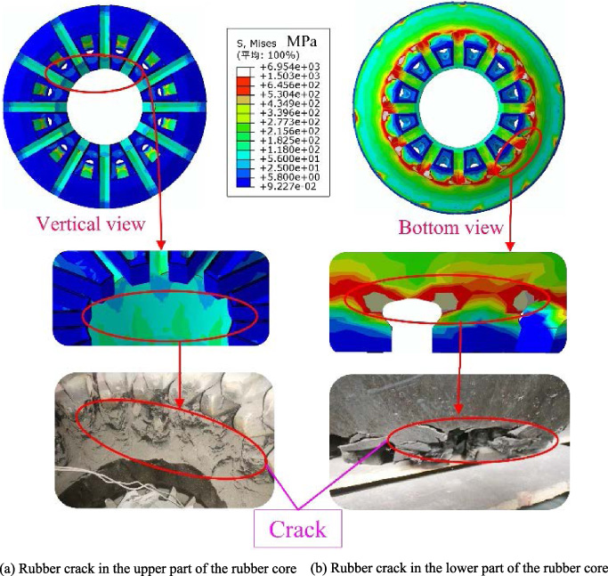
Stress distribution and failure location of the rubber core.
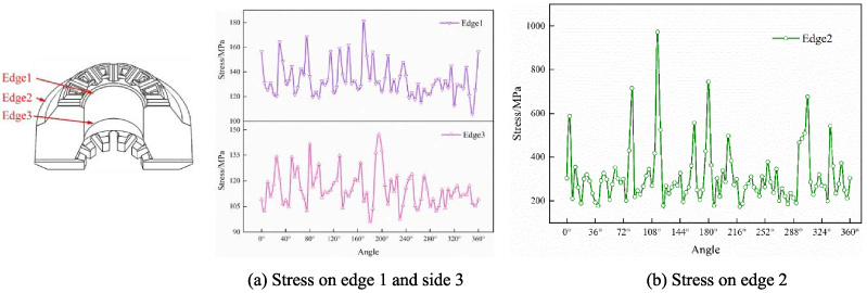
Stress on the three sides at the end of well-sealing.
In order to further study the stress variation law of the rubber core with the well-sealing process, four areas where the rubber core is prone to cracking were selected, and four key nodes were selected in the area. Figure 8 shows the stress changes of the four key nodes during the well-sealing process. Before the rubber core contacts the drill pipe, stress at Node 4 increases gradually. After contact, due to the compression forces between the piston and the rubber core, as well as between the rubber core and the drill pipe, stress exhibits parabolic growth. As the support ribs approach each other, the rubber between the grooves comes into self-contact. Consequently, stress at node 2 steadily increases with the advancement of the well-sealing process. Nodes 1 and 3 are located on the sealing surface, and the stress variation is linked to the rubber core’s interaction with the sealed drill pipe. After the rubber core comes into contact with the drill pipe, the stress initially increases slowly and then becomes stable.

Stress of four nodes.
Figure 9 shows the contact pressure distribution between the rubber core and the drill pipe during the well-sealing process. Due to the presence of wrinkles on the inner wall surface of the rubber core, there are variations in the sealing length along the circumference. The locations with wrinkles have shorter sealing lengths and lower contact pressure, resulting in a contact pressure distribution composed of a combination of high-stress and low-stress regions. From the contact pressure distribution on the surface of the drill pipe, it can be preliminarily judged that the lower end area of the inner wall of the rubber core is the main part of sealing the drill pipe.
Figure 10 shows the contact pressure distribution of the drill pipe along the axial and circumferential directions. Figure 10(a) depicts the contact pressure curve for edge 1, with the rubber core’s sealing length approximately 300 mm. The nodes with the highest contact pressure values appear at two locations: the first at 28 mm and the second at 238 mm. Selecting the edges along the circumferential direction corresponding to these two nodes as edge 2 and edge 3, the primary sealing regions of the rubber core contacting the drill pipe are analyzed. Figure 10(b) represents the contact pressure curves of side 2 and side 3. Due to the uniformly spaced vertical strip-like distribution of contact pressure along the circumferential direction of the inner rubber core wall, minor fluctuations are observed in the contact pressure curves of edges 2 and 3, and the contact pressure ranges between 20 and 46 MPa. The contact pressure of the minimum contact of side 3 is greater than that of side 2, indicating that the main part of the rubber core sealing drill pipe is the lower end area of the inner wall.
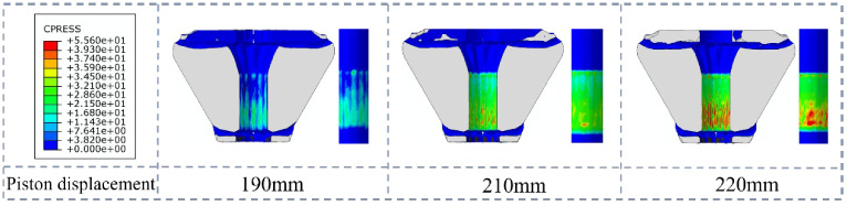
Contact pressure distribution of rubber core and drill pipe during well-sealing.
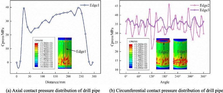
Contact pressure of the drill pipe.
Nodes from the high-stress region around the support ribs are selected, and the stress at each point changes with the displacement of the piston as shown in Fig. 11. The support ribs primarily bear radial and axial loads while regulating uniform deformation of the rubber core. The stress distribution is largely consistent across each unit, hence any one of them can be chosen for study. The upper plate of the support rib is a cantilever structure, which is subjected to the combined action of rubber extrusion and top cover limit during sealing, resulting in high stress in area 2. The rubber at the rear end of the lower plate of the support rib is thin, and it is in indirect contact with the piston. Stress generated here is much greater than in the rest of the positions, which is prone to fatigue damage. Before the displacement of the piston is 137.5 mm, the stress of nodes 1, 2 and 3 increases slowly, the stress of node 4 increases parabolically. After the displacement of the piston is 137.5 mm, nodes 2 and 4 have different degrees of stress mutation, node 2 experiences a relatively minor decrease in stress, whereas node 4 shows a sharp and abrupt decline in stress. This is due to the fact that the lower end of the rubber core is level with the lower end of the piston cone surface, with continued piston movement, the lower end of the rubber core slides into the piston chamber, resulting in the lower part of the support ribs no longer having indirect contact with the piston.
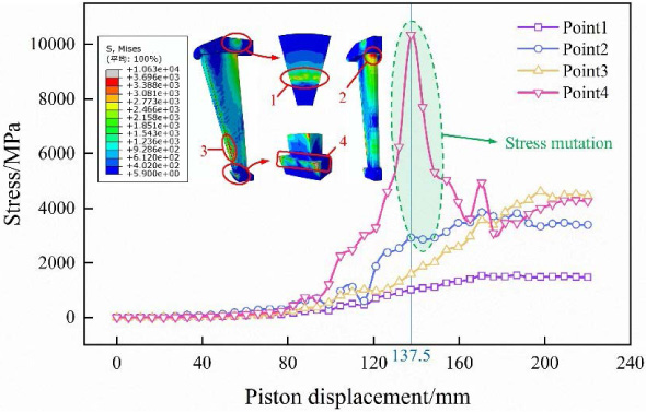
Stress at key nodes of support rib.
Radial displacement of the rubber core.
Comparison of the rubber core deformation
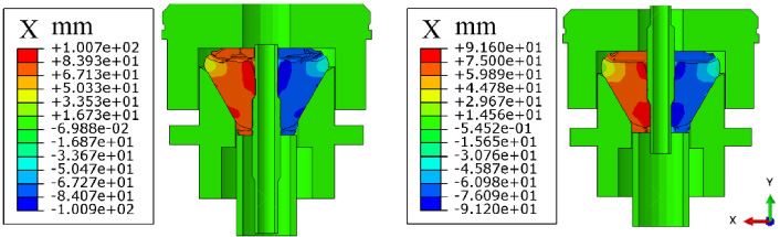
Due to the distinct structural characteristics of the drill pipe joint and the middle section of the drill pipe, the state also differs when the rubber core is sealed in these two different locations. Figure 12 shows the radial displacement of the rubber core at the end of the well-sealing. The rubber core’s sealing joint upper shoulder exhibits a maximum displacement of 100.9 mm, while the sealing joint’s lower shoulder experiences a maximum displacement of 91.6 mm. The larger displacement positions for both are located at the upper end chamfer of the drill pipe and the inner wall of the rubber core.
Figure 13 shows the strain of the rubber core sealing joint. Figure 13(a) represents the strain of the upper shoulder of the rubber core sealing joint, Fig. 13(b) represents the strain of the lower shoulder of the rubber core sealing joint. The strain distribution of both is similar to that of the sealed drill pipe. Greater rubber strain is observed around the support ribs. The difference lies in the strain of the inner wall cylindrical region, where the rubber core exhibits lower strain in the contact region with the joint and higher strain in the contact region with the drill pipe.

Strain of the rubber core.
Figure 14 shows the strain curves of the two paths of the rubber core. In path A, the strain of the rubber core sealing the upper and lower shoulders is close, and in path B, the strain of the rubber core sealing the lower shoulder is greater than that of sealing the upper shoulder, indicating that the deformation is greater when the rubber core sealing the lower shoulder of the joint. Strain in path A is greater than that in path B, indicating that the upper chamfer of the inner wall of the rubber core is more deformed than the lower chamfer.
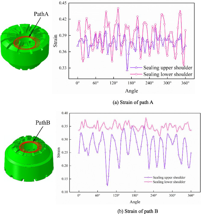
Strain on two paths of the rubber core.
Figure 15 shows the stress of rubber core path C. Path C1 is the path to the upper shoulder of the rubber core sealing joint, and path C2 is the path when the lower shoulder of the rubber core sealing joint. In Fig. 15(a), point a is located in the contact area between the chamfer of the inner wall of the core and the drill pipe, point b is located in the contact area between the rubber core and the upper shoulder of the drill pipe joint, and point c is located in the chamfer area of the lower end of the inner wall of the rubber core. In Fig. 15(b), point a is located in the contact area between the rubber core and the lower shoulder of the drill pipe joint, and point b is located in the chamfer area of the lower end of the inner wall of the rubber core. After passing through the shoulder, the stress of both paths shows a change of decline and rise, which is due to the greater degree of extrusion at the lower end of the rubber core, resulting in greater stress near the chamfer of the lower end of the inner wall of the rubber core. Therefore, when the rubber core sealing the shoulder of the drill pipe joint, it is prone to damage and reduces the service life.
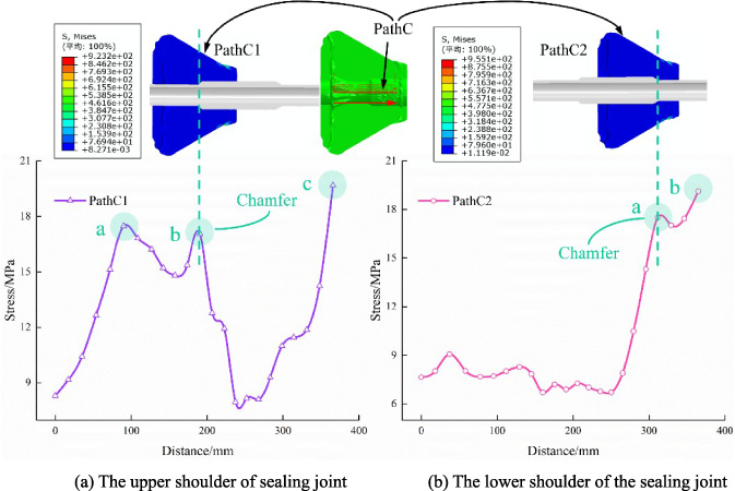
Stress of path C of the rubber core.
Figure 16 shows the contact pressure of the rubber core path C. As the outer diameter of the joint is larger than the outer diameter of the drill pipe, a gap is formed when the rubber core sealing the shoulder, which resulting in a decrease in the contact pressure. As a result, when the drill pipe is sealed by the rubber core, a sealing buffer zone is formed at the joint’s shoulder, leading to a degradation in the sealing effectiveness.

Contact pressure of path C of the rubber core.
Deformation of the rubber core
In the actual working situation, the blowout preventer needs to seal the drill pipe of different sizes. Strain of the rubber core sealing the drill pipe of different sizes is shown in Fig. 17. When the 5 in and 5.5 in drill pipes are sealed by the rubber core, the overall deformation of the rubber core remains consistent. When the 4 in drill pipe are sealed by the rubber core, the inner wall of the rubber core appears obvious striped wrinkles, leading to the sprouting of cracks, which seriously affected the sealing performance of the rubber core.
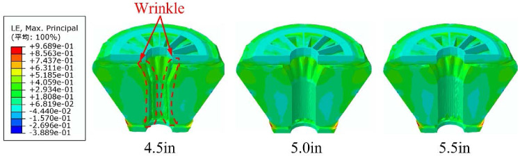
Strain of the rubber core.
Figure 18 shows the contact pressure of the rubber core sealing drill pipe of different sizes. When the rubber core sealing drill pipes of different sizes, the variations in contact pressure on the rubber core sealing surface follow a similar pattern. This is because the condition for wellbore sealing requires the contact pressure between the rubber core and the drill pipe to be greater than the annular pressure in the wellbore. During the well sealing process, the deformation of the rubber core follows a consistent pattern, while the annular pressure in the wellbore remains constant. Under the condition that the piston moves up with the same stroke, as the size of the drill pipe increases, the contact pressure on the rubber core sealing surface also increases.
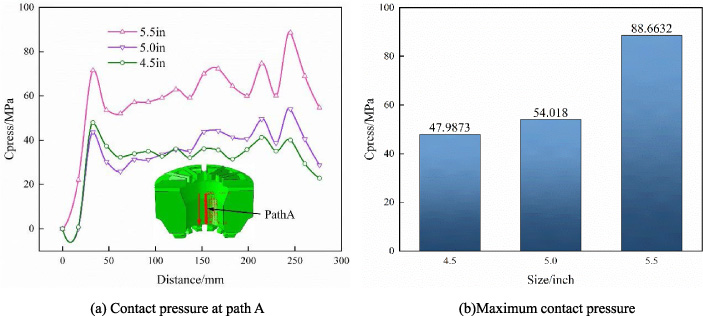
Contact pressure of the rubber core.
Contact pressure of the drill pipe.
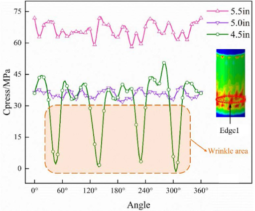
Figure 19 shows the contact pressure of edge 1 for drill pipe with different sizes. When the 5.5 in and 5.0 in drill pipes are sealed, the fluctuation amplitude of the contact pressure on the surface of the drill pipe is small. When the 4.5 in drill pipe is sealed, there are four regions on the drill pipe surface where the contact pressure undergoes significant changes, corresponding to the wrinkled regions on the inner surface of the rubber core. This indicates that the sealing performance is poorest at the locations where the rubber core exhibits wrinkles.
(1) The phenomenon of stress concentration is evident at various locations, including the contact area between the rubber core’s tapered surface and the piston, the grooves between the upper and lower ends of adjacent support ribs, and the chamfers on the inner wall of the rubber core. These factors are significant contributors to the failure of the rubber core. Additionally, the upper plate’s neck region and the lower plate’s back region of the support ribs experience higher stress levels, making the support ribs prone to fatigue fractures.
(2) When the rubber core sealing the drill pipe joint, the contact pressure of the sealing buffer zone at the shoulder of the joint will decrease, and the sealing effect become worse. The deformation of the rubber core sealing joint is greater than when sealing the drill pipe. The deformation of the lower shoulder of the rubber core sealing joint is greater than that of the upper shoulder. The lower end of the inner wall of the rubber core is the main sealing area.
(3) In the process of sealing the well, due to the support ribs close to each other to squeeze the rubber, the inner wall of the rubber core will produce strip wrinkle, weaken the sealing performance of the rubber core. The phenomenon of wrinkles becomes more pronounced as the size of the sealed drill pipe decreases. When the displacement of the piston is the same, the larger the drill pipe size, the better the sealing effect. Therefore, appropriately increasing the piston displacement can improve the sealing performance of the rubber core.
Footnotes
Acknowledgements
This research work was supported by Key Core Technology Research Projects of China National Petroleum Corporation Limited (2021ZG08).
Declaration of competing interest
The authors declare that they have no known competing financial interests or personal relationships that could have appeared to influence the work reported in this paper.