
Abstract
The main goal of this research is to evaluate the strain energy in a brittle material during the interaction of the semi-infinite crack with a neighboring micro-crack. The problem is formulated by considering a cracked thin plate having a micro-crack that rotates around itself and around the semi-infinite crack whose the cracked plate is subjected to a uniform load under mode I. During the interaction between the semi-infinite crack and micro-crack, the strain energy and stress field can be generated at the crack tip of semi-infinite crack. The theoretical analysis of this interaction is treated mathematically by the complex potentials functions. It is shown that the positioning of the micro-crack relative to the semi-infinite crack leads to amplification, reduction and absorption of the strain energy at the crack-tip. The theoretical results agree with those found numerically.
Introduction
The interaction between semi-infinite crack and micro-crack has a significant impact on stress intensity factors, resulting in change in strain energy in the vicinity of main crack. However, in the case of brittle materials, the strain is very small, leading many researchers to neglect the strain energy in their study. The interaction between a semi-infinite crack and neighbouring micro-crack has been extensively studied by various authors [14,20,22,23]. The different methods, including analytical analysis, potential and variable complex method as well as numerical analysis, have been used to investigate these interactions. Recently, considerable attentions has been devoted to investigating the influence of micro-cracks on the stress and strain distribution in the vicinity of the semi-infinite crack [6]. Emiel et al. [4] experimentally investigated the strain energy release rate in metallic alloys. This study show that the similarity parameter was proportional to the cyclic strain energy release rate and the crack extension during cyclic loading was determined by the range of this strain energy.
In this paper, the research aims to evaluate the strain energy by determining their values for each position and orientation of the micro-crack with respect to the semi-infinite crack. Based on using the stress fields approach developed by Hamli [5], the problem is formulated for a thin plate composed by brittle material. The plate is cracked at the end with a surrounding micro-crack that rotates around itself by an angle α and also around the main crack by an angle θ as shown in Figure 1. The cracked model is subjected to a uniform load according to the first mode of fracture. The stress and strains fields for the case of a micro-crack interacting with a semi-infinite-crack are determined using the complex potentials functions [3]. This research work is divided into three parts, the first one is devoted to the determination of the strain energy; based on stress field which the equation of strain energy was developed mathematically by considering the strain field. The second part is for the study of the orientation (θ) of the micro-crack around the main crack, where the strain energy is obtained for each position of the micro-crack. In the third part, the orientation of the micro-crack around itself (α) is taken in consideration in the analysis during the interaction.
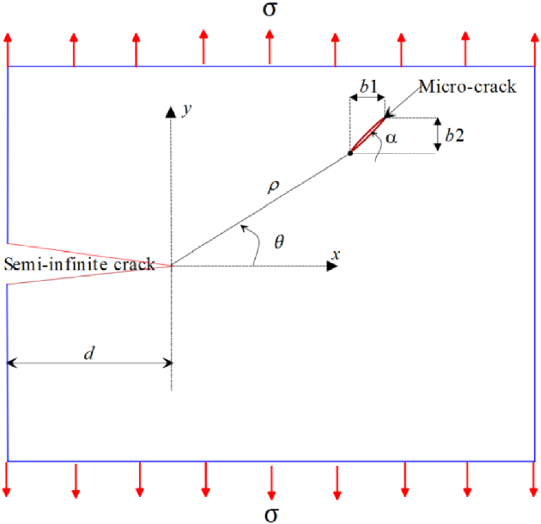
Existing micro-crack in the vicinity of a semi-infinite crack where ρ is the distance between the semi-infinite crack and micro-rack. d is the semi-infinite crack length. b1 and b2 are the dimensions of the micro-crack along the x and y axis successively.
On the basis of obtained strain energy results, the position of the micro-crack leads to amplification, reduction and absorption the strain energy. The theoretical model is numerically analyzed by the finite element method (FEM) using the ABAQUS, whose numerical and theoretical results of strain energy are compared between them.
The brittle failure occurs suddenly by cleavage generated during separation of the atoms forming the material. In brittle materials, it is experimentally observed that failure only occurs if the material suffers plastic deformation, which shows that micro-cracks or defects are created during the plastification of the material [10]. The sudden failure strength of a brittle material is determined by the critical value of the stress intensity factor in mode I [1,9,16], it varies according to the chemical composition and the property of the cracked material. The stress intensity factor in mode I, can be linearly calculated by the stresses which tend towards infinity at the end of semi-infinite crack [11]. It makes to determine the size of micro-crack and effective in stopping of the cracking and consequently controlling the necessary and sufficient qualities [12]. K
I
represents a physical characteristic of the material determined experimentally under conditions. In linear elasticity, the distribution of the plane stresses in the vicinity of the semi-infinite crack is expressed in polar coordinates [21];
For an element of brittle material having a semi-infinite crack, the propagation of this one modifies the surface of their lips [7]. The total energy conservation of the cracked system is given as follows [19]

Interaction between a micro-crack and a semi-infinite crack generates a high concentration of stress at the crack tip [8,24]. The semi-infinite crack is determined by their length d. On the other hand, the micro-crack is defined by Burger’s vector (b = bx + iby). During the interaction between semi-infinite crack and micro-crack, a damage zone surrounding the initial crack occurs with a high concentration of stresses. It is considered to be a highly disturbed area and also called the fracture process zone. Extension of semi-infinite crack is possible in a small zone near to the initial crack in which, strain energy is released. The elastic behavior of cracking during the presence or absence of micro-crack has been studied by several researchers from various disciplines such as metallurgy, mechanics, physics [13,17,18]. In our case, the interaction is ensured by a semi-infinite crack with a neighboring micro-crack that undergoes an orientation θ around the crack tip and around itself with angle α as shown in Figure 1. The loading is applied according to the mode I where the main crack opening is perpendicular to their lips.
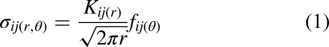
Strain energy values around the semi-infinite crack (case of micro-crack is parallel and perpendicular to the semi-infinite crack); a) α = 0, b) α= π, c) α = π/2, d) α = 3π/2.
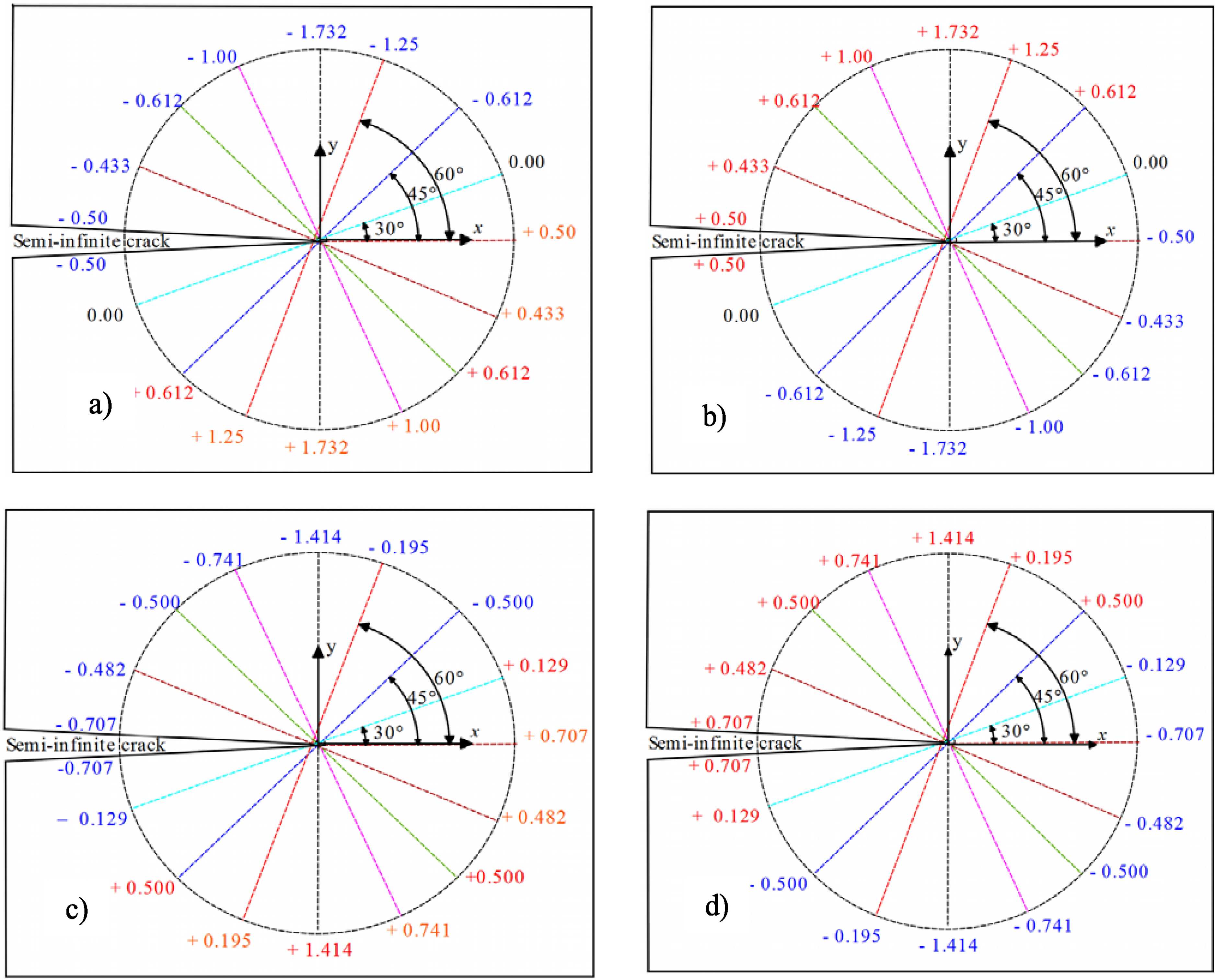
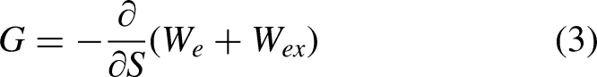
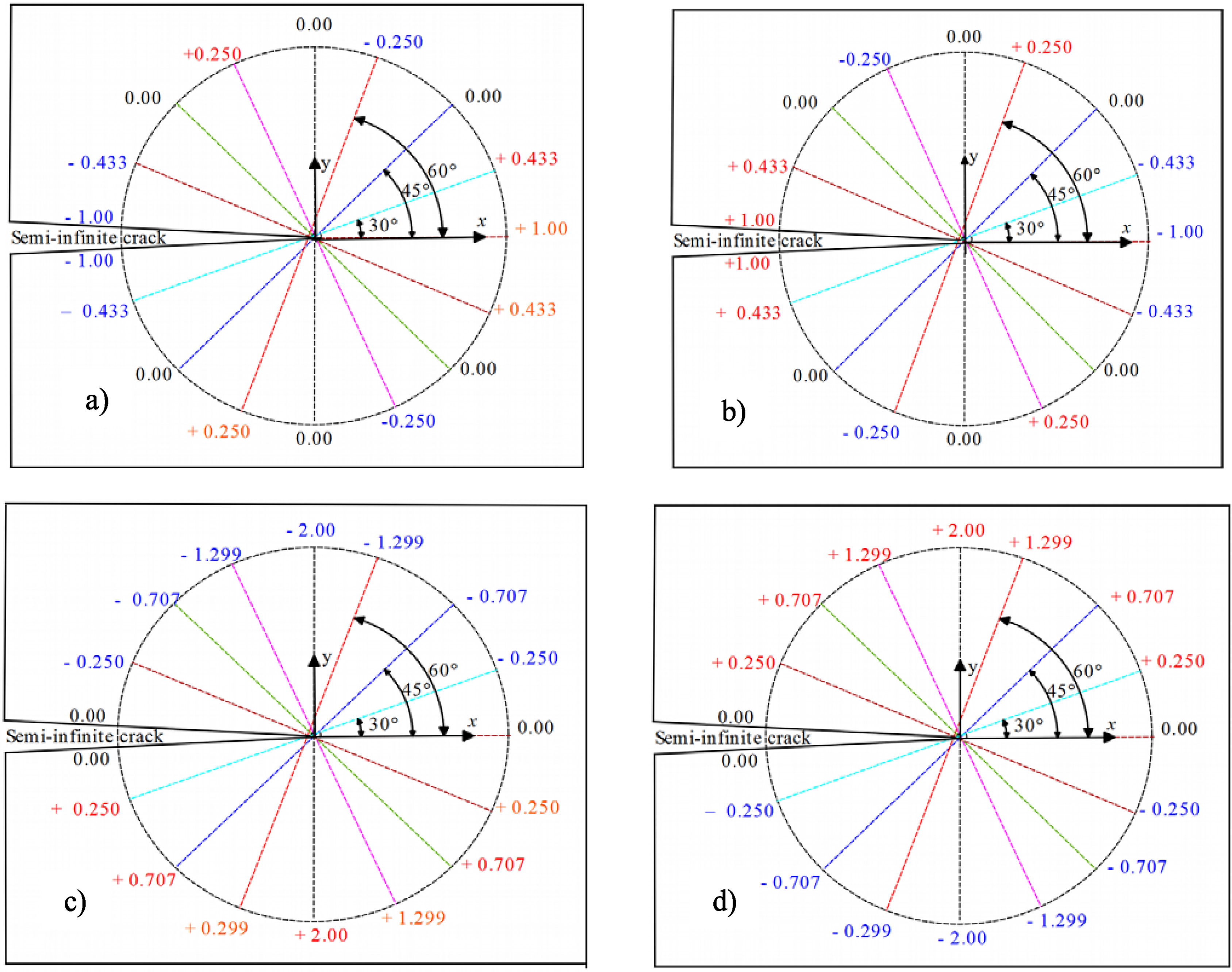
Strain energy values around the semi-infinite crack in case of the micro-crack inclined compared to semi-infinite crack; a) α = π/3, b) α = −π/3, c) α = π/4, d) α = −π/4.
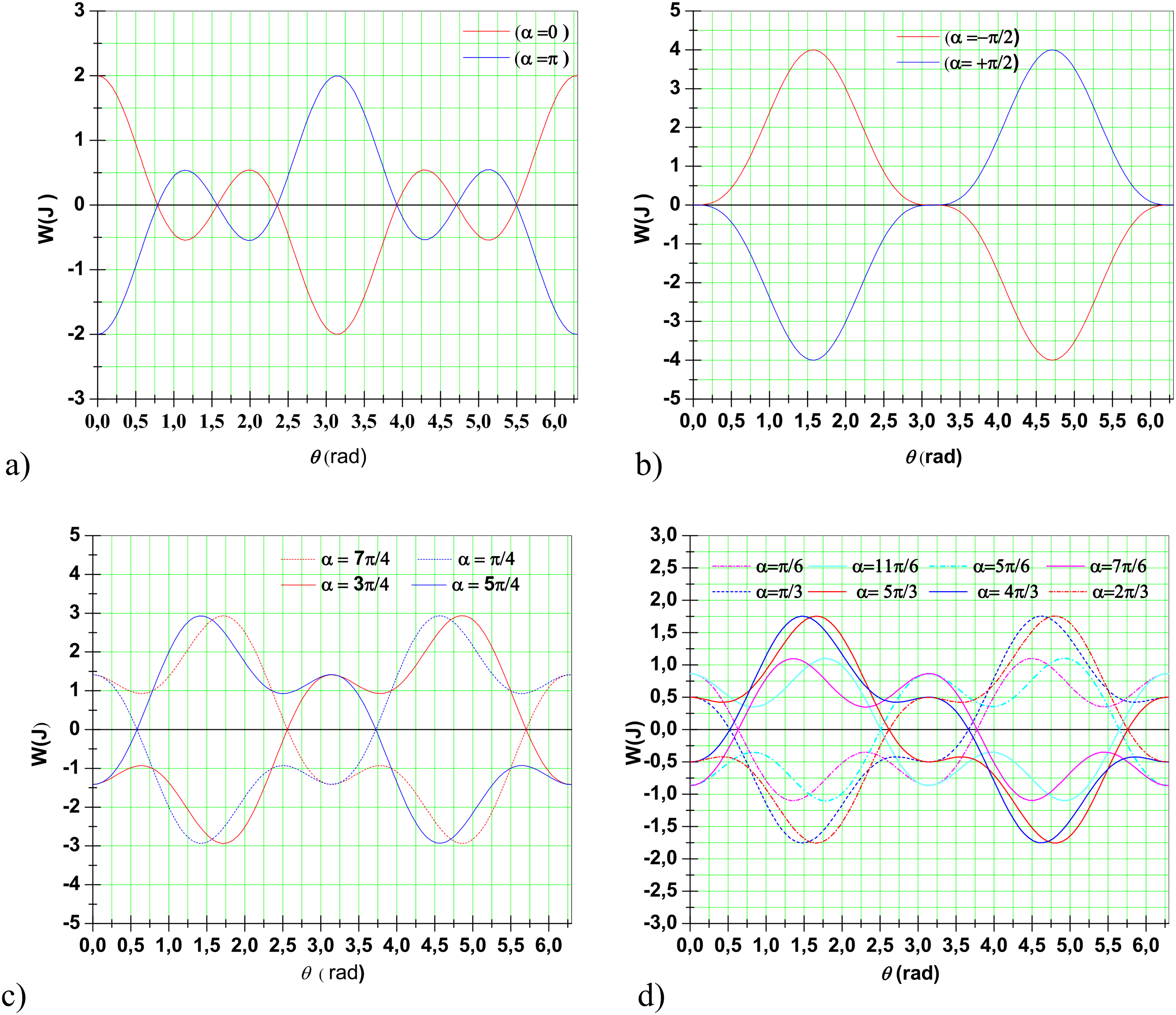
Strain energy variation as function of the orientation angle of the micro-crack around the semi-infinite; a) micro-crack is parallel to the semi-infinite crack, b) micro-crack is perpendicular to the semi-infinite crack, c) micro-crack inclined by π/4 compared to semi-infinite crack, d) micro-crack inclined by π/6 compared to the semi-infinite crack.
The problem of the interaction (crack-micro-crack) is formulated in terms of complex potentials for a plane stress [2]. The total plane stress generated at the crack tip during the crack-micro-crack interaction, are given as a function of complex potentials;
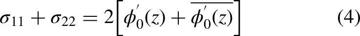


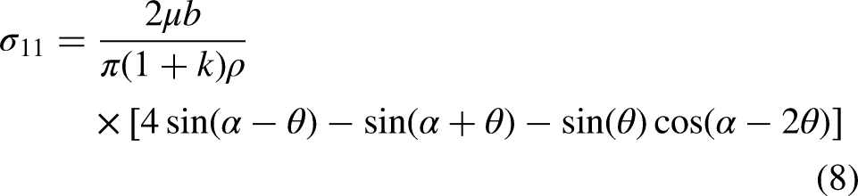
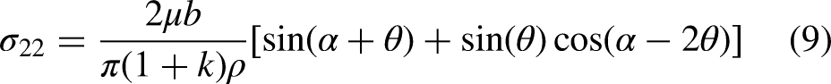
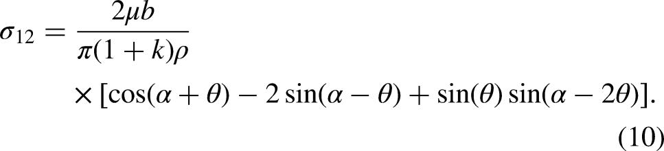
The stress field generated during the interaction between the semi-infinite crack and a neighboring micro-crack, represents the superposition of two stress fields produced by the semi-infinite crack and the micro-crack. The stress found at the main crack tip, are characterized by a factor called stress intensity factor. The orientation of the micro-crack around the main crack can generate a stress field and consequently release the strain energy in each zone of the material. Using Eqs (4) to (7), Hamli [5] determined the stress field generated during the interaction between the main crack and a surrounding micro-crack as follows;
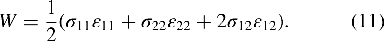
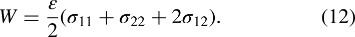
The strain energy is generated when the body deforms, the constituent atoms of which reorganize under the effect of an external load. When this loading is released, the whole system of the body returns to its initial state. This energy is applied to materials with brittle behavior and it is considered to be an essential parameter of failure [15]. In linear elasticity, the strain energy is given by the following formula according to stress and strains of material;
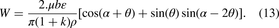
Orientation of the micro-crack around itself and around the semi-infinite crack, gives a strain energy in each point of the material. For a fixed orientation of a micro-crack around itself while varying the orientation angle of micro-crack with respect to the main crack, one can get the following figures (Figures 2–3) representing values of strain energy around the semi-infinite crack.
For a fixed angle of orientation of the micro-crack around herself, Figure 4 show the variation of strain energy function of the angle of orientation of micro-crack with respect to the main crack.
Strain energy vs. angle orientation of the micro-crack around itself: a) Case where micro-crack is parallel and perpendicular compared to x-x axis, b) micro-crack inclined by π/3 to the x-x axis, c) micro-crack inclined by π/4 to the x-x axis, d) micro-crack is inclined by π/6 compared to x-x axis.
Orientation of the micro-crack around itself generates stress, displacements and strain energy. For a steady orientation angle of micro-crack with respect to the main crack while changing the orientation of this micro-crack around itself, we obtain the following figure.
Numerical analysis
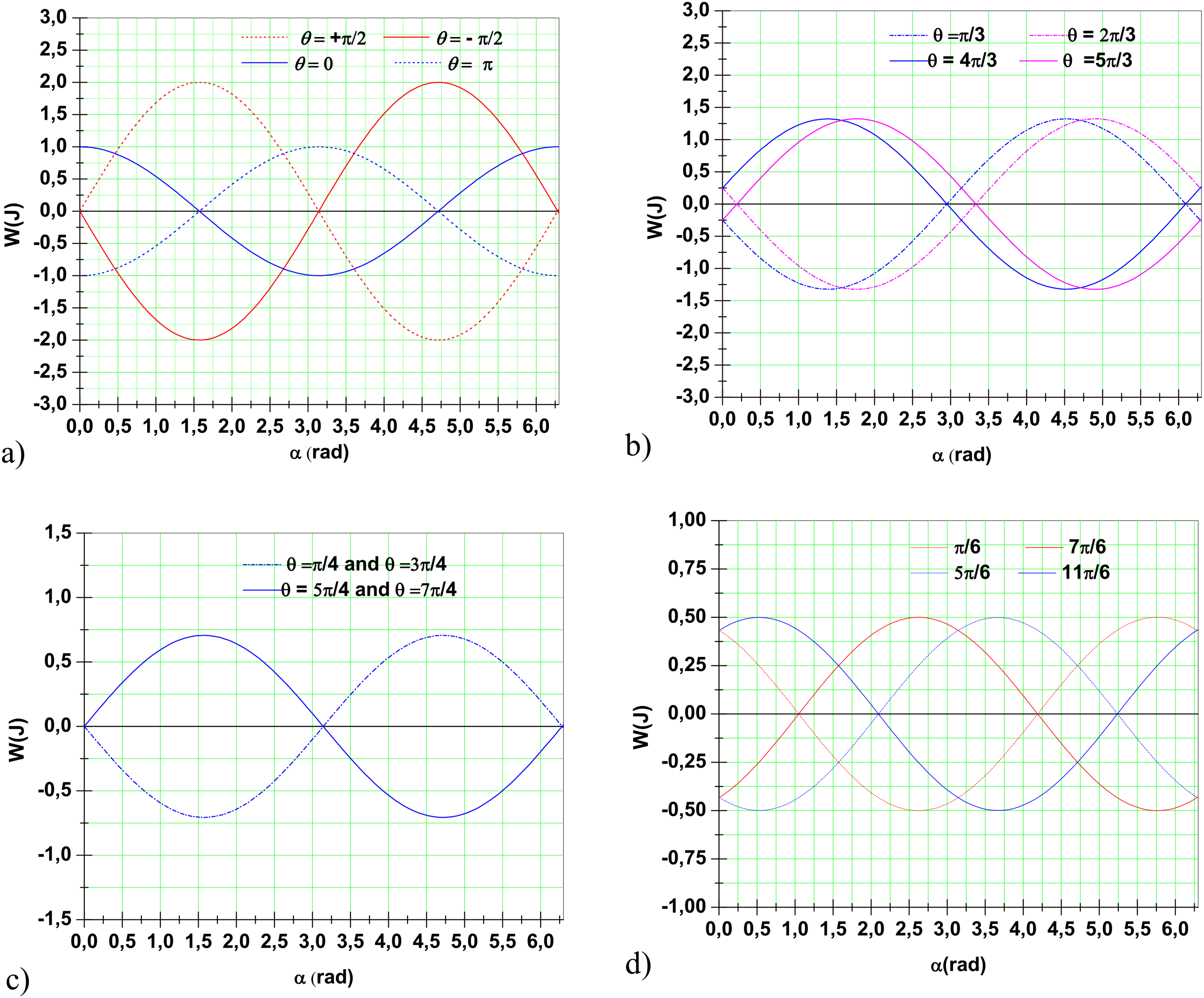
Influence effect of the micro-crack on the semi-infinite crack is numerically analyzed by FEM using the ABAQUS. Numerical analysis has to determine the values of stress, strain and strain energy. The numerical model is a plate element (600 × 400 × 5) mm having a semi-infinite crack and a neighboring micro-crack with diameter d, subjected to a loading varied from zero to 50 N/mm according to Mode I (see Figure 6). Chosen material is characterized by an elasticity modulus E = 72 000 MPa and a Poisson’s ration = 0.22. The model is discretized by square finite elements and others triangular at the end of the crack. In this study, the boundary conditions are respected by freeing the displacements according to the first mode of rupture and fixing them according to the second and third mode (mode II and mode III).
Model of a cracked plate with the presence of a micro-crack.
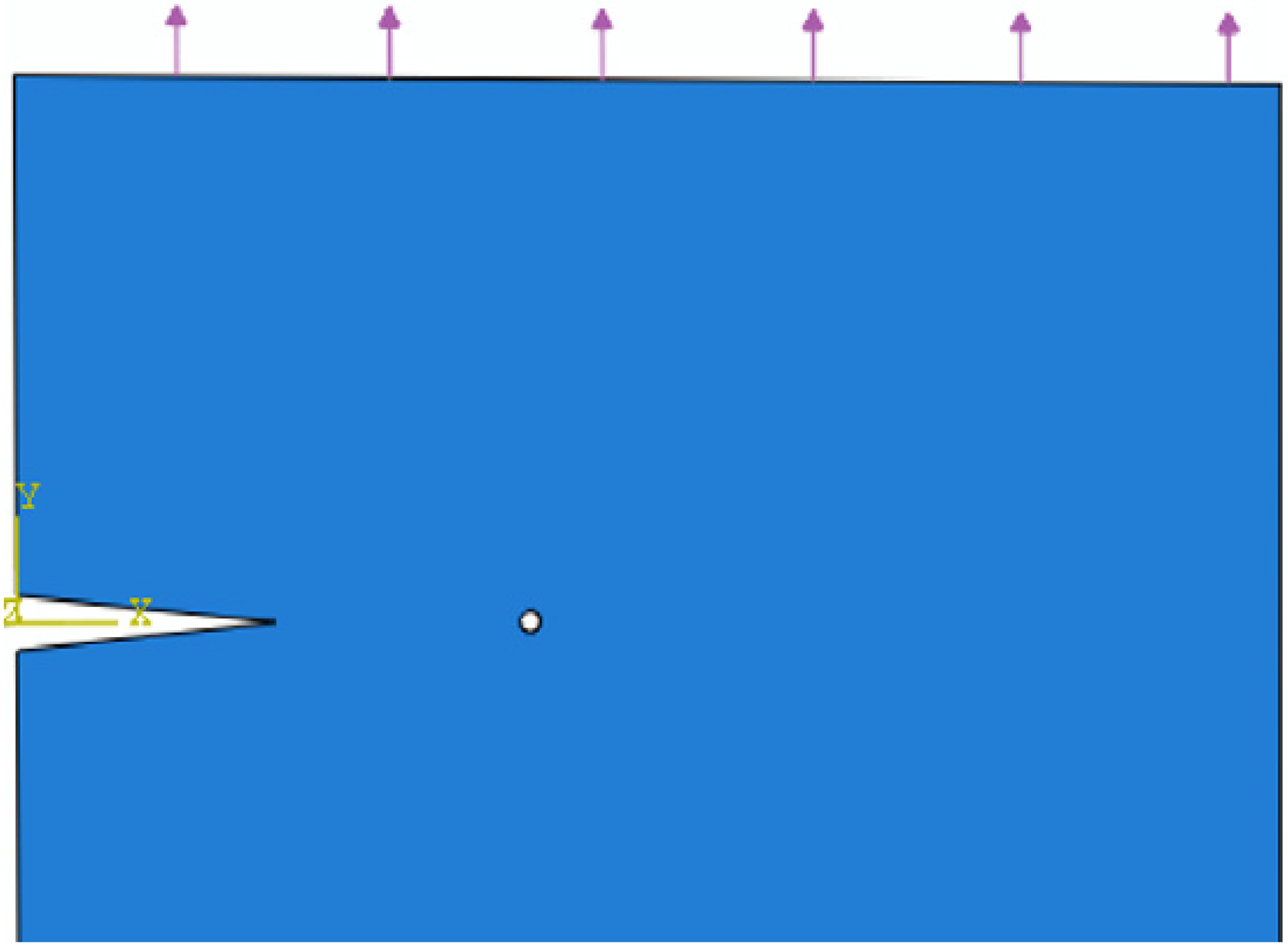
By varying the applied load and also the diameter of the micro-crack, stress, strain and strain energy in each zone of the material can be determined. Figure 7 represents the plane strains and stress whose the values are obtained for the case of a micro-crack with a diameter of 10 mm and loaded with 20 N/mm.
Plane strains (ε ij ) and stress (S ij ) for a micro-crack of d = 10 mm, loaded by 20 N/mm. a) ε11, b) ε22, c) ε12. d) S11, e) S22, f) S12.
Figures 8–9 represent numerical variations of the plane stress, strains and strain energy as a function of the diameter of micro-crack and applied loads, respectively.
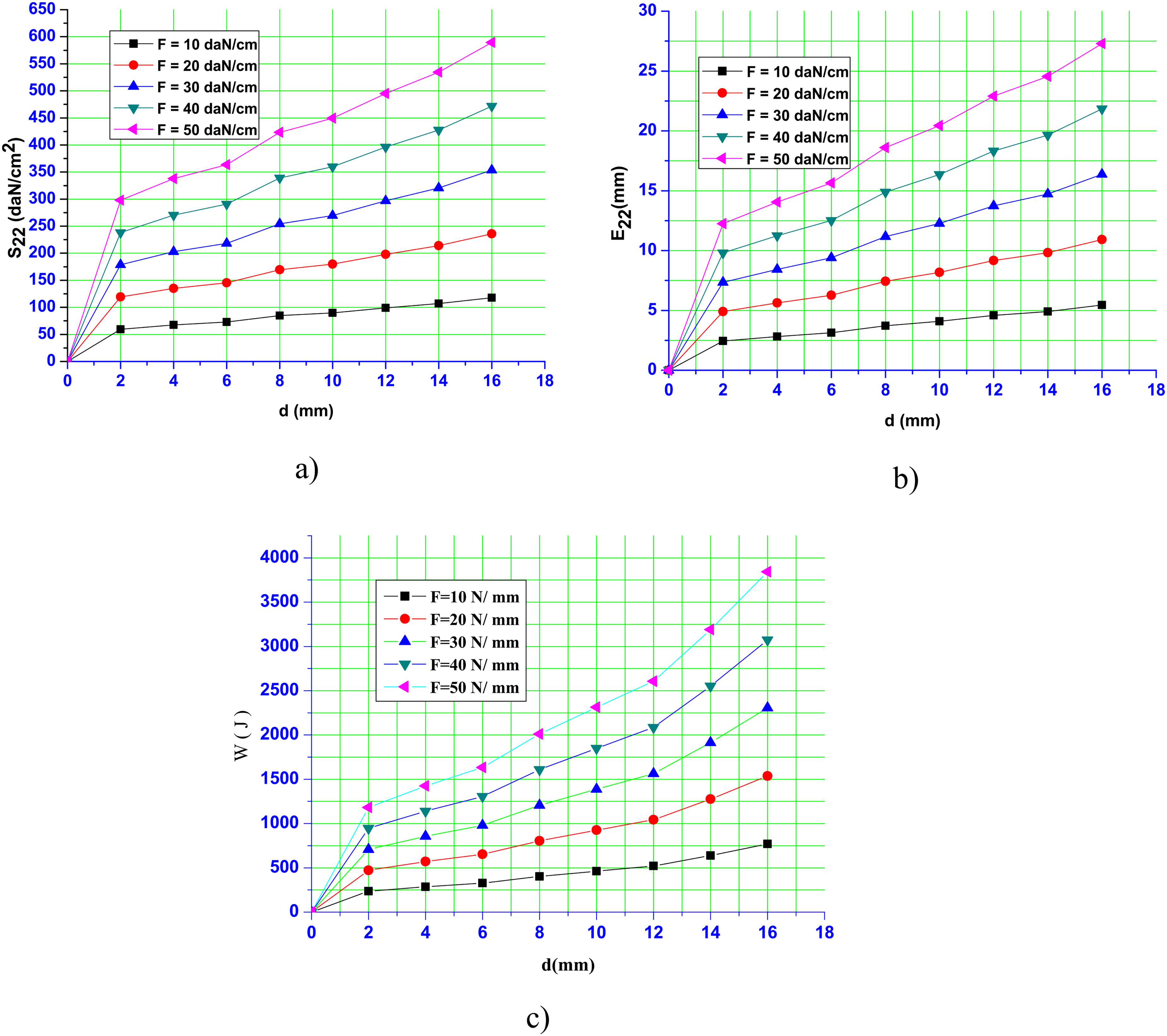
Plane stress, strains and strain energy vs. diameter of the micro-crack (d) in case of F = 10 N/mm, 20 N/mm, 30 N/mm, 40 N/mm and 50 N/mm; a) stress (S22), b) strains (ε22), c) Strain energy (W).
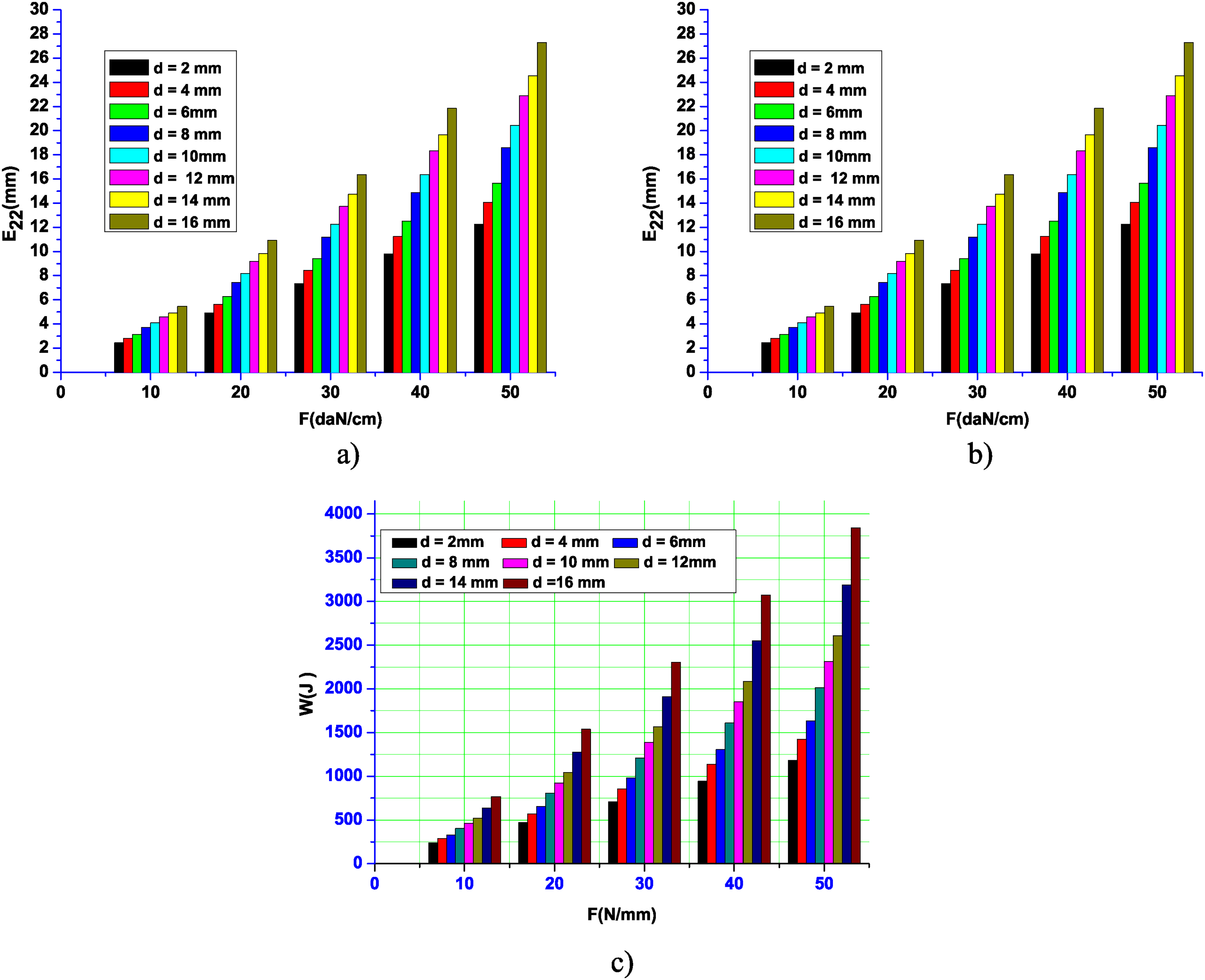
Plane stress, plane strains and strain energy vs. applied load (F) in case of d = 2 mm, 4 mm, 6 mm, 8 mm, 10 mm, 12 mm, 14 mm and 16 mm; a) stress; S22(F), b) strains; ε22(F), c) strain energy; W (F).
The variation of the strain energy as a function of the diameter of the micro-crack and the applied loads, can be represented theoretically and numerically in Figure 10.
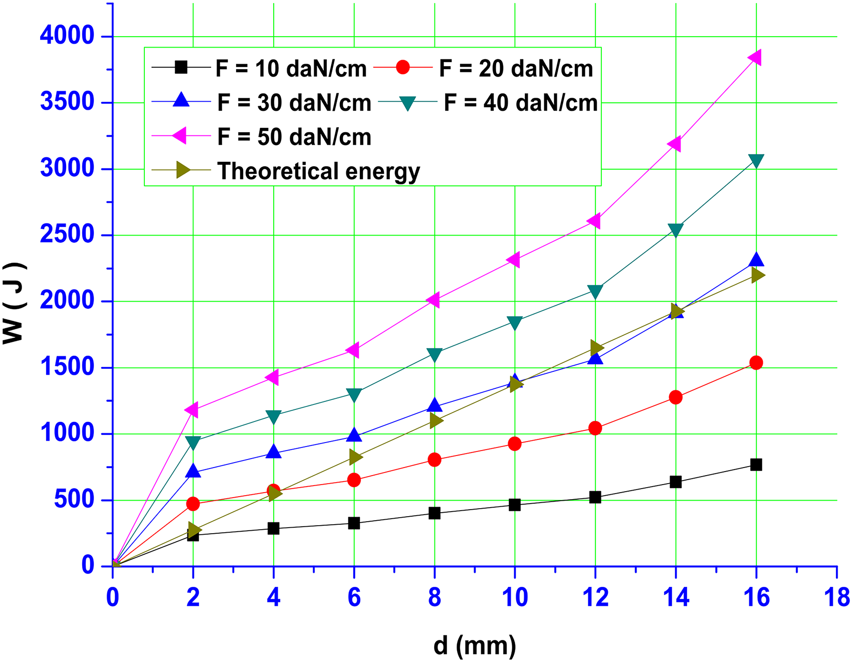
Theoretical and numerical strain energy W vs. diameter of the micro-crack (d). Case where F = 10 N/mm; 20 N/mm; 30 N/mm; 40 N/mm; 50 N/mm.
In this research study, strain energy is formulated taking into consideration the position and orientation of a micro-crack with respect to the semi-infinite crack. Obtained results have shown the limiting areas of amplification, reduction and absorption of the strain energy at the semi-infinite crack tip. It is shown here in the following descriptions;
Figures 2–3, represent the positioning of the micro-crack around the semi-infinite crack and around itself (
From Figure 2(a,b), in the case of a micro-crack parallel with respect to the semi-infinite crack (α = 0 et α = π), there is no strain energy then the micro-crack is located on the y-y axis (θ= 90° and 270°). It reaches the maximum value once the micro-crack is positioned in the axis x-x (θ= 0° and 180°).
On other hand, Figure 2(c,d) represents a micro-crack perpendicular to the semi-infinite crack (α = π/2 et = 3π/2). In this particular case, one can notice that there is no strain energy released in case the micro-crack is then located in the x-x axis. It reaches the maximum value when the micro-crack is located on the y-y axis.
According to Figure 3(a,b,c,d) where the micro-crack is tilted with respect to the semi-infinite crack, the strain energy values are found to be symmetrical with respect to the crack tip.
For an orientation angle of the micro-crack around itself and around the semi-infinite crack, Figure 4 represents amplified, reduced and absorbed strain energy.
Table 1 summarizes the areas where amplification or shielding (reduction) effects take place and also the absorption of the strain energy at the main crack tip.
Limiting area of amplification, reduction and absorption of the strain energy.
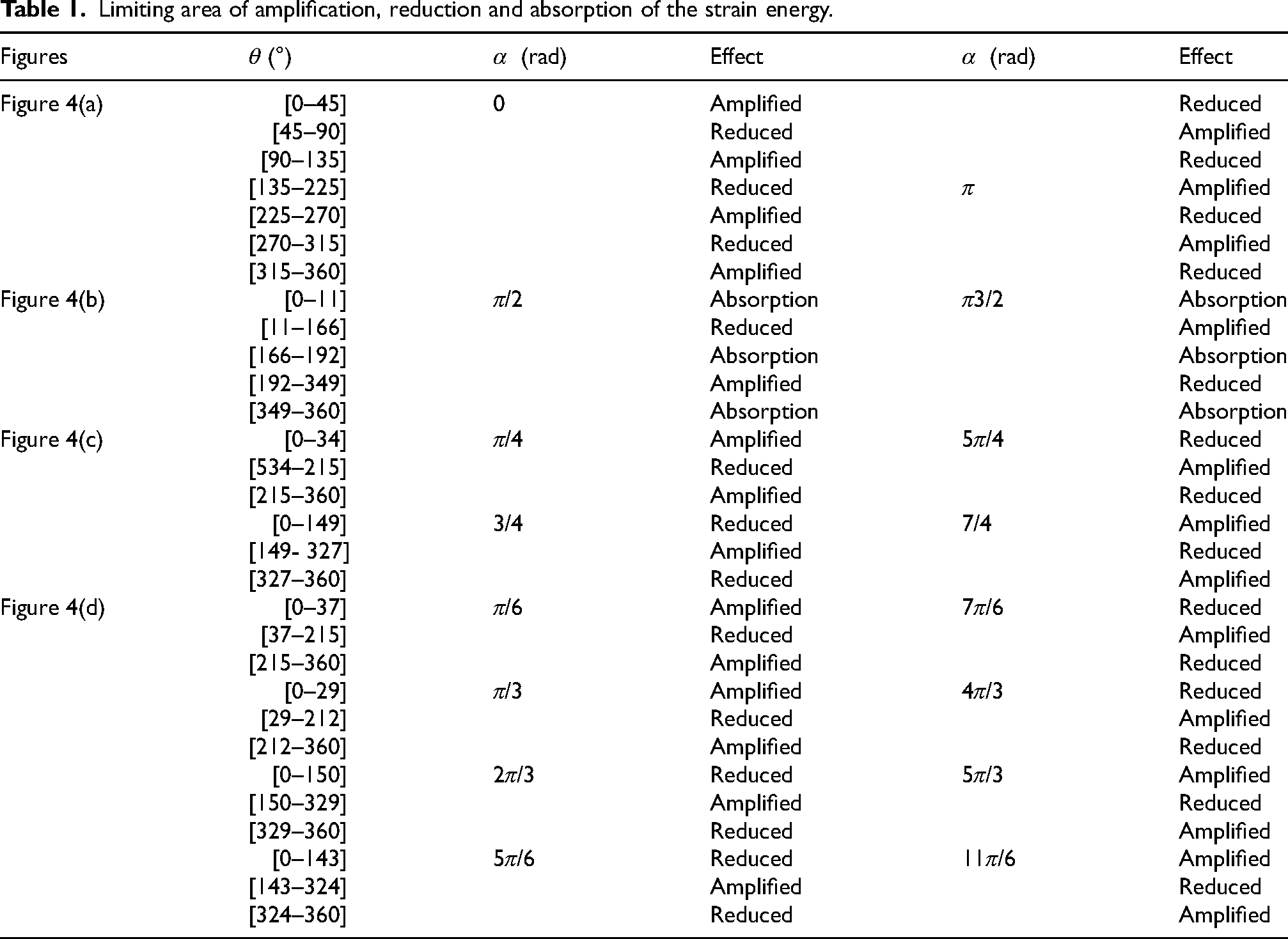
Limiting area of amplification, reduction and absorption of the strain energy.
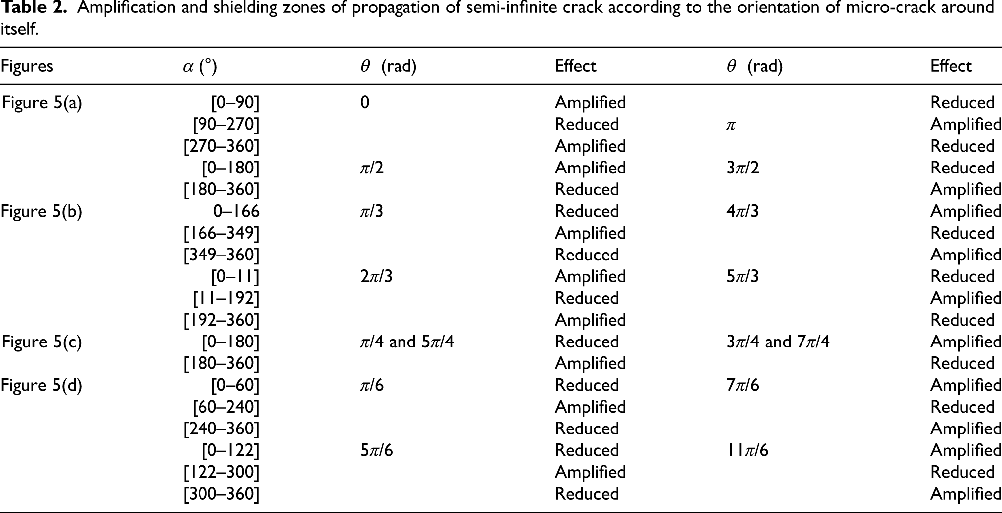
Maintaining the position of the micro-crack with respect to semi-infinite crack and varying the orientation of this micro-crack around itself, Figure 5 show the effect of the micro-crack on the strain energy at the main crack tip. Table 2 groups the zones of amplification and reduction of the strain energy.
Amplification and shielding zones of propagation of semi-infinite crack according to the orientation of micro-crack around itself.
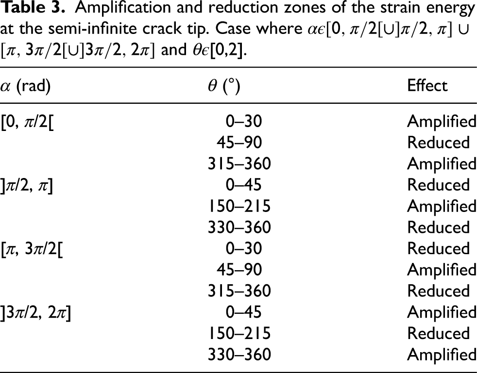
Amplification and reduction zones of the strain energy at the semi-infinite crack tip. Case where
According to Table 2, the presence of a micro-crack in the vicinity of the semi-infinite crack can amplify, reduce and also absorb the strain energy at the main crack tip. For a giving position of the micro-crack with respect to the semi-infinite crack (
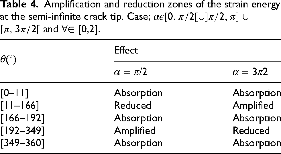
Amplification and reduction zones of the strain energy at the semi-infinite crack tip. Case;
The theoretical model is numerically treated using a thin rectangular element as shown in Figure 6 whose plane stress and strain results are determined (see Figure 7).
The Figures 8–9 show that the plane stress, strain and strain energy increase proportionally with the diameter of the micro-crack and loading applied. By varying the applied loading, Figure 10 represents the numerical and theoretical variation of the strain energy as a function the diameter of micro-crack. The numerical and theoretical values of the strain energy increase with the diameter of the micro-crack, including the small offset between them which is generated by the thickness of the numerical model being neglected in the theoretical analysis.
In this research work, the main objective is to evaluate the strain energy in a brittle material during the interaction between a micro-crack and a semi-infinite crack while varying the orientation angle of the micro- crack around the main crack and around itself. Whatever the positioning of the micro-crack with respect to the semi-infinite crack, the strain energy values are symmetrical to each other around the crack-tip, also the presence of a micro-crack in a perpendicular position to the semi-infinite crack absorbs the strain energy at the crack tip (x-axis) and generates the maximum strain energy on the y-y axis. On the other hand, the parallelism between the two cracks (micro-crack and semi-infinite crack) absorbs the strain energy in the y-y axis. By varying the size of the micro-crack, the theoretical results are comparable with those found numerically while recording a small shift which is generated by the thickness effect of the plate considered in the numerical analysis. Based on the results found in this paper, the orientation of the micro-crack plays a significant role in delaying the propagation of the main crack by the absorbing the strain energy at the crack tip. This criterion is essential in engineering practice for the effective monitoring of structural integrity.