



Abstract
BACKGROUND:
Identifying obstacles and potholes in the pathway of the visually impaired have received much attention. While much has been done on the detection of obstacles, in the design of electronic mobility aids, much more is needed to be done on the detection of holes and drop-offs, especially those that are affordable and hands-free. This paper therefore considers the development of a wearable electronic mobility aid.
METHODS:
The developed system is based on the multisensor fusion approach of detection which combined three techniques, namely: a source of laser light, a camera and an ultrasonic sensor. A red line generating laser source is used to project a straight line and this is captured by the camera. The red line is deformed differently on coming in contact with holes or standing obstacles. The pattern of deformation is then extracted for obstacle and pothole recognition. The visibility of laser light is greatly reduced when the scene is extremely illuminated, so this is complemented with edge detection. The edge detection uses edges in the identification of holes and obstacles. This is combined with ultrasonic sensing, so that the presence of obstacles can be differentiated from that of holes. The outcome of detection and the distance of obstacles from the blind are relayed via an audio cue.
REDULTS:
Its evaluation showed better performance compared to the guide cane. It showed a reduction in collision rate by 83.25% and reduction in falling rate by 84.62%. The device received good acceptability from the users.
Introduction
It has been observed that out of the 7 billion world population, about 285 million persons suffer from visual impairments, with about 39 million people suffering from total blindness and about 246 million suffering from low vision [1]. Visual impairment has become a global challenge without exceptions to the developed nations [2]. Efforts have been made on several fronts to develop various mobility aids for persons with visual impairments. Devising modern means of navigation for the visually impaired persons has become an important subject of interest of research. Some levels of successes have been attained, however, there are some limitations inherent in the existing solutions that often reduce the effectiveness of their use [3].
The oldest navigation assistance for eye defective persons are based on the use of white cane (i.e. walking cane) and that of the guide dogs. The walking stick was found helpful as it enhances the navigation of the blinds to successfully discharge their regular daily duties. However, there is still some form of limitations with it. One of these limitations is that, a walking stick can only detect below-knee objects [4]. Another is that it can only detect obstacles that are within the immediate radius of the stick and with higher likelihood of the blind getting hit by the obstacle most times because of the short response time.
Trainable domestic animals such as horses, dogs, etc., were adopted as navigation aids for the blinds. However, this method is very costly and requires a lot of training. The use of these methods often suffers some drawbacks as they convey little information to users. They are less user-friendly and often require special skills and training [2]. Recent developments have seen various designs of Electronic Travel Aid (ETA) which are aimed at assisting the visually impaired persons to travel in a safe and independent manner. In [5], a multidimensional walking aid was developed using a network of ultrasonic sensors to detect obstacles in three directions (i.e. left, right and the front of the blinds). A light dependent resistor was used to sense when it is getting dark, and consequently prompt the blind. But the proposed method did not address the problem of identifying potholes on the way. In [6], an approach was proposed in which infra-red sensors were attached to the users shoe, at the front and at the two sides of the shoe, to detect obstacles in three different directions. A colour sensor was employed through which the blind could also detect obstacles. Image processing techniques have also been employed to assist the blind to move freely in an unfamiliar scene. In [7], a smart cane was developed to enhance the navigation of the blind both in indoor and outdoor environments.
An image acquisition device was used to capture the image of the walk path and then sent to a PC computer for processing. Because a PC required for the image processing, it becomes a burden to be carried around. In [8], a smart vision system for the visually impaired was developed for the detection of obstacles both for the interior and the exterior environments. In [9], a user selectable modes smart cane was designed to assist the blind to move within and outside the room. The user can switch the mode depending on the decision either to move within or outside a building. Each of the selectable modes was designed to detect both below-knee and above-knee obstacles. In [10], a wearable belt around the waist with a network of four ultrasonic sensors strategically arranged was proposed. The arrangement was to detect both standing obstacles and holes. A computer was used as the processor which the user would have to carry as he walks. This approach may not allow the blind to move freely as he would have to use his hand to support or carry the device. Two of the ultrasonic sensors were slightly tilted to detect holes. The major concern with this method is that there are possibilities of some holes having a texture that is not very reflective, giving rise to weak reflected waves that may not be easily sensed by the ultrasonic module thereby escaping detection. Though an image processing was later adopted in [10] to aid the detection, it could be very difficult to differentiate edges of potholes from the edges of standing obstacles. Even with this, there is still a major drawback as the focus has mostly been on the avoidance of extruding obstacles which prevents the suitability for general purpose use [3]. Though, much work has been done on the detection of standing obstacles, there is much to be done in holes detection for the blind. It is observed that holes pose the greatest challenge for the blinds [10]. Also, most visually impaired persons still prefer the use of the old walking stick to some of the Electronic Travel Aids, because some of them are either very bulky, expensive and many cannot provide effective detection of holes on the walking path. In [11] an obstacle detection system with multiple (infrared and ultrasonic) sensors was considered. The sensors were attached to the front part of the shoe, and the sensed signal is sent to a receiving part where it is processed to generate the required alert to the user. Its design, however, does not detect drop-offs. A good review of most of the existing ETA is provided in [12]. A recent design in [13] uses generated light patterns pointed at the field of view of a camera. The captured images of the matrix of the points is then analysed. The deformation of the pattern of light follows the object over which it is projected. Deep neural network consisting of convolutional neural network and Long short term memory units is then applied for classification of the object. The device developed is light and evaluated to have high accuracy, however it is not hands-free.
A method presented in [14] was a prototype developed on a walking stick for detecting obstacles and water puddles in the direction of the user. Another walking stick using an ultrasonic sensor and a moisture sensor was proposed in [15]. The ultrasonic sensor was attached to the stick at an angle of 40 degrees to detect holes or stairs. Though this can detect obstacles and stairs it cannot detect potholes because they have weak reflected waves. In [16], effort was made to address pothole detection. To achieve this, four ultrasonic sensors were arranged on a walking stick. Three of the sensors were arranged to sense obstacle on the left, right and front directions and the last sensor was placed below the walking stick to detect potholes. A predetermined distance was set between the sensor and the ground level. So a longer distance was expected when the stick passes over a hole and this increase in distance was used to detect the presence of a pothole. The problem with this approach is that this distance may vary and thereby give a false alarm while walking depending on the placement angle of the stick.
Most recent approaches employ the technique of computer vision or image processing in detecting objects in the path of the user. An approach considered in [17, 18] made use of the RGB-D camera and an ultrasonic sensor. Images of most commonly encountered standing obstacles were collected and stored in a database. The detection is then done by comparing what is captured by the camera with those in the database. The distance of the obstacle was measured by the ultrasonic sensor. The system was able to detect both obstacles and potholes and communicate via an audio message to the user. One problem with this is that objects not in the database may go undetected if encountered while walking. Another issue identified with the method was that it failed to classify the objects detected, so the user could not determine if what is detected is an obstacle or a pothole. Other contributions that made use of both vision and depth information for ETA and navigation sysem designs have been reported [19, 20, 21]. Another ETA that integrates both sensor-based and image processing techniques with multiple object detection was presented in [22]. The design is reported to have 100% accuracy in detection of obstacles, however, the design did not consider the detection holes and drop-offs.
It has been observed, in [23], that the visually impaired usually have their confidence increased when they have a better perception of their environment. Therefore, in addition to creating awareness of the presence of objects, it is necessary that people with visual impairments have an idea of the kind of objects (i.e. either obstacles or potholes) before them. It is also important to ensure that electronic mobility aids (EMAs) affordable and hands-free. These thus formed the major focus of this study.
The instrument design
The proposed system, as shown in Fig. 1, is based on the multi-sensor fusion approach to detection. The system is composed of three sub-units, namely: the sensing unit, the processing unit and the alerting unit. The sensing unit consists of three transducers: a camera, an ultrasonic module and a laser module. Upon these transducers are developed three techniques in the processing unit for the detection of depression/hole or obstacle. The first technique uses the ultrasonic module to detect obstacles. The second technique is designed around the laser module and the camera. It uses the methods of image processing to accomplishes the detection process. The third technique is solely based on the images from the camera and methods of image processing to detect obstacles or depression. While each of the sensing techniques can detect obstacles, only the first method, that uses the ultrasonic module cannot effectively detect depression or hole in the ground.
Block diagram of the system.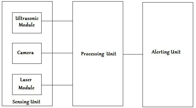
The sensing unit has all the three transducers purposely attached to a waist belt. The camera is positioned on the belt at an angle to the vertical to generate a red line on the ground at a distance of 1 m away from the feet of the user. Though the camera has a viewing range greater than 1.73 m and a viewing width of 2 m (i.e. 1 m each sideways), a shorter distance of 1 m and a width of 1.2 m is purposely used to ensure clear capture of the projected laser line. This is because of the normal adverse effect of the ambient illumination on the brightness and sharpness of the red line generated by laser. The ultrasonic sensor is also tilted to the vertical at the same angle with the camera.
The processing unit
The processing unit consists of a Raspberry Pi 3B which is connected to the three transducers of the sensing unit. It is also connected to the alerting unit. The three transducers connected to the Raspberry Pi are: USB camera, ultra-sonic sensor, earpiece. The USB camera which served as the image capturing device was connected directly to one of the two USB ports of the Raspberry Pi. The earpiece, serving as the user interface that relays distance information to the user, was connected to the audio/composite output jack of the Raspberry Pi. The Raspberry Pi and Laser device are both powered from a portable power bank. The other USB port of the Raspberry Pi was used to supply 5V from the power bank to it using a USB cable.
Technique 1: Using the ultrasonic module
An ultrasonic sensor is a transceiver module. The output pin (TRIG) of the ultrasonic sensor was connected to the GPIO 23 (Pin 16) of the Raspberry Pi while the input pin (ECHO) that reads reflected signal was connected to GPIO 24 (Pin 18) of the Raspberry Pi. The input voltage (i.e. 5 V) from ECHO pin of the ultrasonic sensor was limited to a safe operating voltage of 3.3 V using a voltage divider before connection to Pin 18 of the Raspberry Pi. It detects obstacles through the emission and reception of reflected short pulses from obstacles. It emits a short burst of 40 kHz which travels through air, at normal temperature, at a speed of 340 m/s. The ultrasonic sensor detects an obstacle on the floor at various distances away from the ultrasonic sensor. Thus, the ultrasonic sensor logically detects the presence of obstacle and also gives the estimate of the distance of the obstacle.
The actual distance was measured using a steel tape rule and was compared with the calculated distance,
Comparison of actual distance with measured distance
Comparison of actual distance with measured distance
The second technique detects standing obstacles and holes by using a source of laser light and a camera. The laser source is used to generate a reference ray of light, a straight horizontal red line at a certain distance away from the blind. From the principle of refraction of light, the red line tends to bend around obstacle or depression. Therefore, the red line is deformed on coming in contact with either depressed path (e.g. holes), as in Fig. 2), and standing obstacles as in Fig. 2b but remains not deformed on a free path as shown in Fig. 2a. The pattern of deformation is distinct for obstacles and holes as shown in Fig. 2. A camera is continuously focused to capture the scene in front of the blind. With a developed algorithm, the captured image is stored and duplicated into two images using a Raspberry Pi 3B as a processor.
Decision table
Decision table
The pattern of the red laser line (a) without deformation (b) deformation due to obstacle (c) deformation due to depression or drop-off.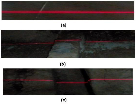
One of the images is extracted for the red line and the pattern is then used to detect and to differentiate obstacles from holes. In the duplicate image, the red line is suppressed to remove its edges leaving the remaining contents of the image. The remaining contents are analysed using edge detection to detect the presence of holes and obstacles. This is necessary to complement the laser mode for detection since laser light can be affected under a condition of extreme scene illumination. With the edge detection, unlike the laser deformation detection, the presence of obstacles is not differentiated from the presence of holes since both use edges as means of detection. However, the output of the edge detection compared with the output of the ultrasonic sensor is used to differentiate the two objects (i.e. holes from obstacles). The analysed outputs of the three detection mechanisms are combined to alert the blind via an audio cue (beeps). This is further explained in the next section. In addition, the ultrasonic sensor is also used in this study to measure the distance of the blind from a standing obstacle. Distance information is transmitted through patterns beeps that vary incrementally with changing barrier distance from the user.
Detection decision
A decision on which object is detected is determined based on the output of edge detection, the pattern of laser line and the output of the ultrasonic sensor. In this study, there are two outputs for edge detection. The first output is when the path is not free, i. e. an object either a pothole or an obstacle on the walk path is detected, and the second output for when the walk path is detected as free. The two state outputs are represented with binary digits 1 and 0 respectively. Since edges are used to detect both obstacles and potholes, a binary digit 1 is used to represent both objects. Unlike the detection by edges, laser line detection was used to give three distinct outputs. The first is when there is no deformation on the line (i.e. when the road is detected as free); the second is when an obstacle is detected and the third for when a pothole is detected. The state outputs are denoted by digits 0, 1 and
The alerting unit
This unit basically is composed of a function that runs on the Raspberry Pi and an earpiece. The function generates beeping signal at different intervals based on the object detected from the result of combined detection decision and the distance of the detected object. The Raspberry Pi 3B has two audio output ports, namely, the HDMI socket and the headphone socket. Two beep frequencies were used, a lower frequency for an obstacle and a higher frequency for a hole detection. However, the number of beeps per time increases as the closeness to the object increases.
System evaluation
The complete system before it was packed in the waist pocket is as shown Fig. 3. A controlled trial experiment was carried out to objectively assess the improvement of the proposed electronic mobility aid through these parameters: object presence awareness (holes and obstacles), detection range and collision/falling rate. The trial was done with 20 (11 Male and 9 Female) volunteers blind users of various demographic data and with varied guide cane usage experience from the Federal Society of the Blinds, Lagos, Nigeria. The inclusion criteria were for the blind individuals within the age range of between 15 to 50 years old, and without other comorbidities that may impair mobility such as mental disorder, orthopaedics impairments, hearing impairments, etc. A randomized four artificial barrier courses were created, of which, the users negotiated two courses (one for obstacles and the other for holes) with the proposed electronic mobility aid and the other two courses with the guide cane following the same arrangement with the proposed electronic mobility aid.
The Complete system.
Participants during the trial sessions. (a) Detecting hole/ drop-off with the EMA; (b) Detecting obstacle with guide cane; (c) Detecting obstacles with the EMA.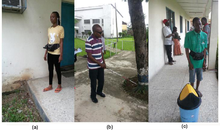
A long tiled veranda of 20 m by 4 m with 4 laid out obstacles such as chairs, Tables, Plastic Drum, etc. was used for the experiment. To avoid map learning effect by the users, the positions of the obstacles were randomize thereby forming two barrier courses (i.e. obstacles). The tiled veranda enabled the accurate measurement of the detection range for the two devices. The other two barrier courses were the artificial holes of 0.61 m by 0.61 m by 0.30 m each created on a plain playing ground. The two pothole locations were randomized to prevent map learning effect by the users. The artificial hole was in essence to assess improvement in the holes detection capability of the proposed device. A boundary line of 0.4m to the respective holes was drawn beyond which no user was allowed to exceed for safety purposes.
Experimental data of the 20 subject
Experimental data of the 20 subject
Footnotes
Acknowledgments
The authors wish to acknowledge the assistance of the authority and management of the Federal School of the Blind, Lagos, Nigeria.
Conflict of interest
The authors have no conflicts of interest to report.