
Abstract
BACKGROUND:
Upper limb rehabilitation robots have become an important piece of equipment in stroke rehabilitation. Human-robot coupling (HRC) dynamics play a key role in the control of rehabilitation robots to improve human-robot interaction.
OBJECTIVE:
This study aims to study the methods of modeling and analysis of HRC dynamics to realize more accurate dynamic control of upper limb rehabilitation robots.
METHODS:
By the analysis of force interaction between the human arm and the upper limb rehabilitation robot, the HRC torque is achieved by summing up the robot torque and the human arm torque. The HRC torque and robot torque of a 2-DOF upper limb rehabilitation robot (FLEXO-Arm) are solved by Lagrangian equation and step-by-step dynamic parameters identification method.
RESULTS:
The root mean square (RMS) is used to evaluate the accuracy of the HRC torque and the robot torque calculated by the parameter identification, and the error of both is about 10%. Moreover, the HRC torque and the robot torque are compared with the actual torque measured by torque sensors. The error of the robot torque is more than twice the HRC. Therefore, the HRC torque is more accurate than the actual torque.
CONCLUSIONS:
The proposed HRC dynamics effectively achieves more accurate dynamic control of upper limb rehabilitation robots.
Keywords
Introduction
As many countries enter an aging society, the global incidence of stroke will increase, and the number of patients with limb dysfunction caused by hemiplegia will increase as well. Research shows that scientific and effective rehabilitation training plays a crucial role in the recovery of limb motor function of stroke patients. Compared with the one-on-one training method of therapists, the rehabilitation effect of the upper limb rehabilitation robot is more significant, because the upper limb rehabilitation robot not only provides adaptive training and highly repetitive movement but also enhances the self-care ability of patients with dysfunction [1, 2, 3]. So far, there have been many assistive or rehabilitation robotics, including ARMin III [4], LIMPACT [5], Alex [6], AAU exoskeleton [7], Harmony [8], CAREX-7 [9], and BONES [10]. The upper limb rehabilitation robot directly acts on the human body, and the human body and the rehabilitation robot are a closed loop. For different patients and patients in different periods, the human-robot interaction is different. Therefore, it is particularly important to model and analyze the dynamics of the human arm and upper limb rehabilitation robots, which can improve the accuracy of the rehabilitation robot and the effectiveness of rehabilitation training and assistance.
Some researchers only considered the mechanical dynamic model of the upper limb rehabilitation robot for convenience [11, 12, 13], and ignored the dynamic model of the human arm, which may lead to inaccurate control of rehabilitation training and assistance. Some researchers take the human as the research object, establish the human upper limb equivalent mechanism and derive its dynamic equations [14, 15, 16, 17]. It is of great significance to study the modeling and analysis of human dynamics, which can guide the design and control strategy of rehabilitation robots. There are also some researchers who proposed the impedance model of the human arm. By adjusting the control parameters of the impedance model, the sensitivity of the model to human-robot interaction can be adjusted and the compliance control of the system can be realized. It is suitable for rehabilitation training of different patients in different periods. The dynamics of post-stroke patients’ upper limbs as an impedance model, and an adaptive control scheme were proposed to control the rehabilitation robot to move stably and smoothly [18, 19]. Some previous studies divided the human-robot interaction control strategy into multiple modes, and realized the active assisting strategy. Zhang et al. proposed the human-robot interaction controller that has three modes, including human-dominant mode, robot-dominant mode and safety-stop mode [20]. Wang et al. evaluated the patient’s motor ability and divides the motor ability into initialization ability, moving ability and stop ability. The magnitude of the assistance in these three stages is different [21].
In the previous studies, the dynamic models of the upper limb rehabilitation robots are mostly modeled only for robots, the human arm, or the human-robot interaction. However, human-robot as a closed-loop system, it is very important to study the human-robot coupling (HRC) dynamics and explore the relationship between the HRC system and the human arm and the rehabilitation robot. In this paper, we model and analyze the HRC dynamics of a 2-DOF upper limb rehabilitation robot (FLEXO-Arm). The HRC torque and the robot torque are solved by Lagrangian equation and step-by-step parameter identification method. The effectiveness of the HRC dynamics is verified by experiments, which provides more reference for the human-robot control strategy.
Methods
The prototype of an upper limb rehabilitation robot (FLEXO-Arm)
In this paper, the HRC model is established for a power assistive robot (FLEXO-Arm) for upper limb rehabilitation. The robot can not only provide continuous rehabilitation training with multiple degrees of freedom (DOF) for stroke patients in different rehabilitation stages but also has multiple movement modes, such as passive movement, active movement, and teaching movement, to meet the rehabilitation needs of different patients. The upper limb rehabilitation robot has two active DOF and eight passive DOF, as shown in Fig. 1. The green arrows denote active DOF, and the yellow arrows denote passive DOF. One active DOF (
Mechanical structure and DOF distribution of FLEXO-Arm. The green arrows denote active DOF, and the yellow arrows denote passive DOF.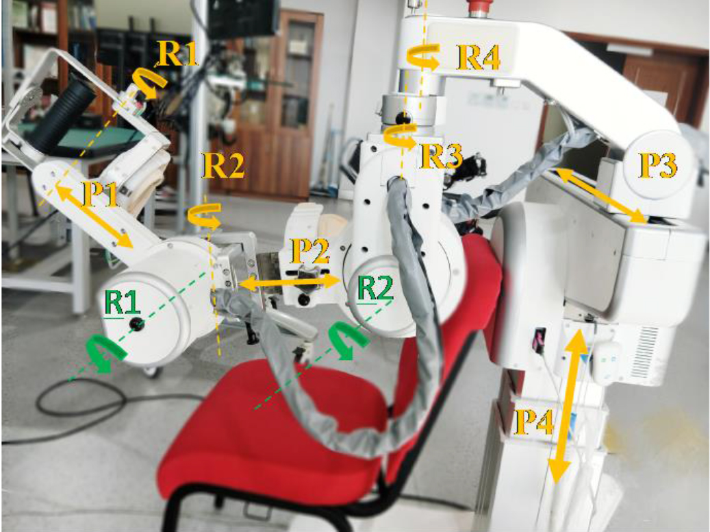
The HRC system of FLEXO-Arm.
The upper limb rehabilitation robot and the human arm are regarded as one system when the HRC dynamics model was established. The joint angles, angular velocities and angular accelerations of the human are consistent with the robot while the human arm moves with the robotic arm, as shown in Fig. 2. The power of the HRC system is the muscle force of the human arm and the force contributed by the robot’s motors. So, the HRC torque is equal to the motor torque of the robot and the muscle torque of the human arm. The HRC torque is obtained as follows:
Here,
For the robot system, the external force of the system is the force of the motor and the interaction force between the human arm and the robot. So, the robot torque is equal to the motor torque and the interaction torque of the robot is as follows:
Here,
For the human system, the external force of the system is the force of the muscle and the interaction force between the robot and the human arm. The torque of human arm is equal to the muscle torque and the interaction torque of the human is as follows:
Here,
With Eqs (1)–(4), we can find the relationship between the HRC torque, robot torque and human torque as follows:
It is known that the upper limb HRC torque is achieved by summing up the robot torque and the human torque through the force analysis of the interaction between the human arm and the robot. Obviously, it is not complete and accurate to only analyze the robot dynamics for the HRC dynamics, and ignoring the human dynamics will lead to inaccurate control of the upper limb rehabilitation robot. This way, the personalized training of patients developed by the therapists cannot be implemented, and the training effect of the patients is reduced. Next, we will solve and compare the robot torque and the HRC torque.
The upper limb rehabilitation robot (FLEXO-Arm) has two active DOF, including shoulder flexion/extension and elbow flexion/extension. The two movements are in the same plane. So the robot can be reduced to a 2-DOF link to analyze its dynamics. The second kind of Lagrange equation is suitable for complete systems, and it can get the dynamic equation of complex systems in the simplest form. The dynamics of a 2-DOF rehabilitation robot can be calculated by the second kind of Lagrange equation, and the following equation is obtained as follows:
Here,
Therefore, the 2-DOF robot dynamic model is proposed as follows:
Here,
Here,
Therefore, the parameters to be solved in the simplified torque Eqs (2.3) and (2.3) include the following nine parameters (
For a 2-DOF link, it corresponds to a parameter set
If we can find the dynamic parameters of FLEXO – Arm, the torque of the robot can be solved by Eqs (2.3) and (2.3). We can assume the robot dynamic parameters set
The purpose of dynamic parameter identification is to accurately calculate the torque required for a robot to carry out a movement according to the identification value of dynamic parameters. So the next step is the identification of
We design three experiments (experiments 1–3) to identify the dynamic parameters of the robot. We can identify the elbow dynamic parameters through experiment 1 and the shoulder dynamic parameters through experiments 2 and 3.
Experiment 1: The shoulder joint of the robot is fixed at
After FLEXO-Arm moved according to experiment 1, we can obtain the angle, angular velocity, angular acceleration and elbow joint torque
Experiment 2: The elbow joint of the robot is fixed at
The data
Experiment 3: The elbow joint of the robot is fixed at
The corresponding dynamic equation of experiment 3 is shown as follows:
The formula of
The data
The nine dynamic parameters of the robot can be obtained through the three experiments (experiments 1–3). The torque of the robot joints can be calculated by substituting these parameters into Eq. (2.3).
We know that the whole body couples the human arm and the robot, which can also be simplified as a 2-DOF link, and the HRC torque can be solved by Eq. (2.3). We can assume the HRC dynamic parameters set
The identification method of the HRC dynamic parameters is the same as that of the robot, except that in the experiment the human and robot move together.
Experiment 4: The shoulder joint of the robot is fixed at
Experiment 5: The elbow joint of the robot is fixed at
Experiment 6: The elbow joint of the robot is fixed at
Experiment 1: The shoulder joint of the robot is fixed at 2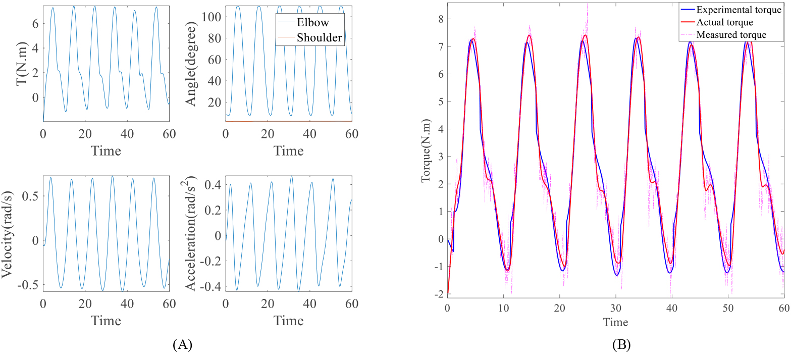
Experiment 2: The elbow joint of the robot is fixed at 28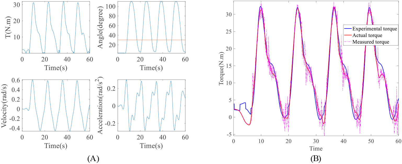
Identification of upper limb rehabilitation robot dynamic parameters
In order to solve the dynamic parameters of the robot, we designed experiments 1–3. The data of these experiments is collected by the robot in one minute, as shown in Figs 3A, 4A and 5A. The two pictures above are the motor torque (T) and joint angle (Angle) are collected by the torque sensor and encoder at the robot joints. The following two figures are the joint angular velocity and angular acceleration. The angular velocity is derived from the joint angle and time, and the angular acceleration is derived twice from the joint angle and time.
The dynamic parameters of the robot
The dynamic parameters of the robot
We can solve a set of dynamic parameters of the robot through experiments 1–3, of which the results are shown in Table 1. After obtaining the values of the parameters, we can solve the experimental torques of the shoulder joint and elbow joint of the robot in reverse as, shown in Eq. (3.1). The actual torque is the elbow joint torque of the robot measured by the torque sensor. The experimental torque is solved by the robot dynamic parameters. In Figs 3B, 4B and 5B, the pink dotted line is the actual robot joint torque without filtering, the red curve is the actual robot joint torque after filtering, and the blue curve represents the experimental torque. In order to quantify the effect of dynamic parameters identification, the root mean square (RMS) evaluation of the experimental and actual values of torque is used [22], as shown in Eq. (17).
Torque RMS of experiments 1–6
Experiment 3: The elbow joint of the robot is fixed at 85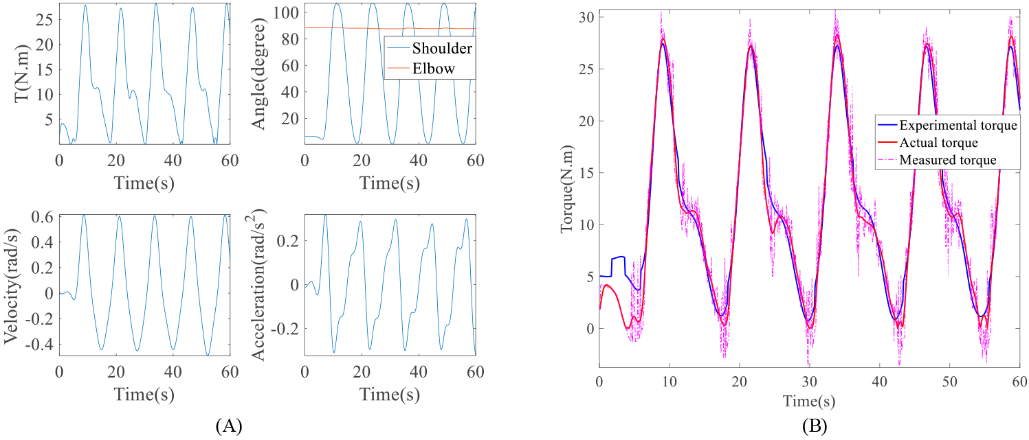
The torque RMS of experiments 1–3 is shown in Table 2. The torque RMS of elbow joint is 0.7608 N.m, the maximum of actual torque measured in experiment 1 is about 7.5 N.m, and the error is 10.1%. The torque RMS of experiment 2 is 2.7999 N.m, the maximum of actual torque measured in experiment 2 is about 35.0 N.m, and the error is 8.0%. The torque RMS of experiment 3 is 2.6704 N.m, the maximum of actual torque measured in experiment 3 is about 28.0 N.m, and the error is 9.5%. The error of shoulder joint is kept within 10%.
In order to solve the HRC dynamic parameters, we designed experiments 4–6. The data of these experiments is collected by the robot in one minute, as shown in Figs 6A, 7A and 8A. The data acquisition and processing of HRC parameters identification are the same as those of the robot parameters identification. We can solve the HRC parameters through experiments 4–6, of which the results are shown in Table 3. After obtaining the values of the parameters, we can solve the experimental torques of the shoulder joint and elbow joint of HRC in reverse, as shown in Eq. (3.2).
The dynamic parameters of HRC
The dynamic parameters of HRC
Experiment 4: The shoulder joint of the robot is fixed at 2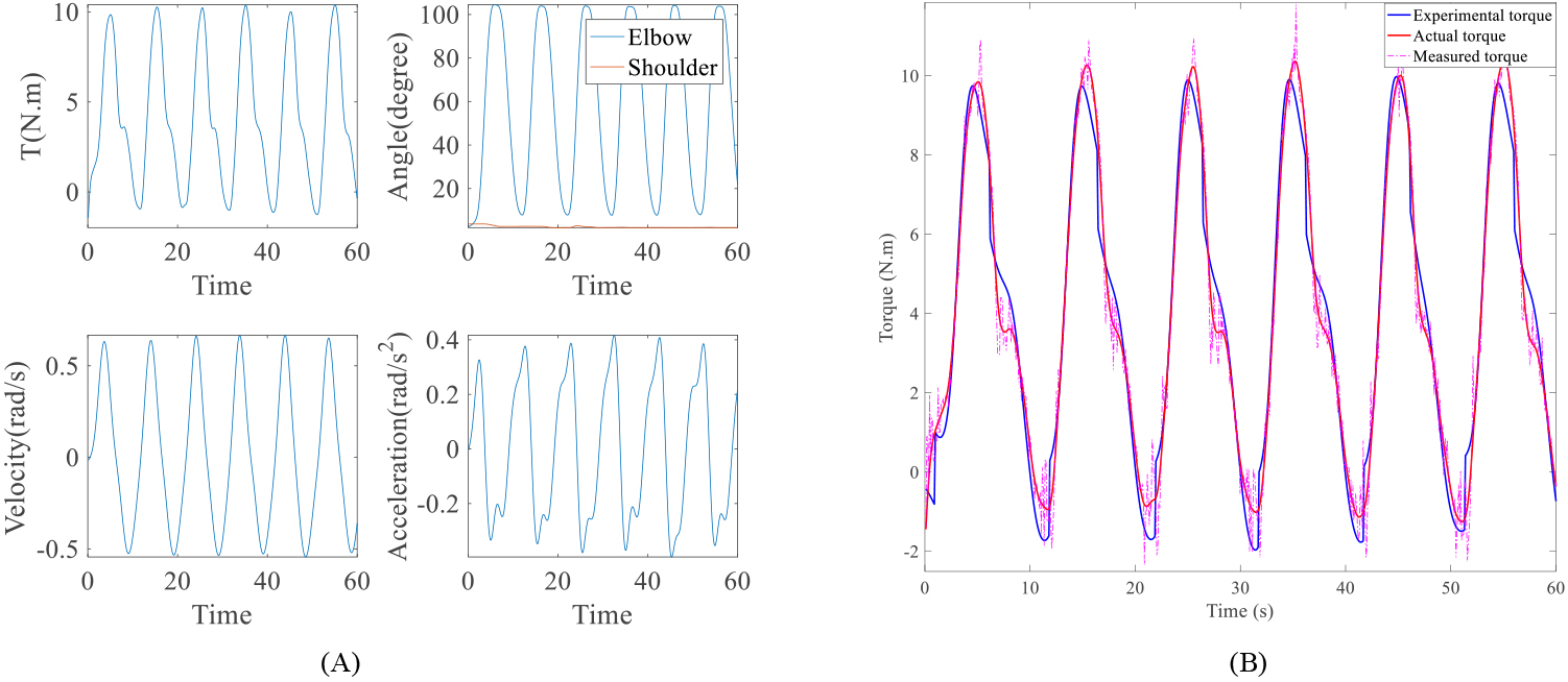
Experiment 5: The elbow joint of the robot is fixed at 28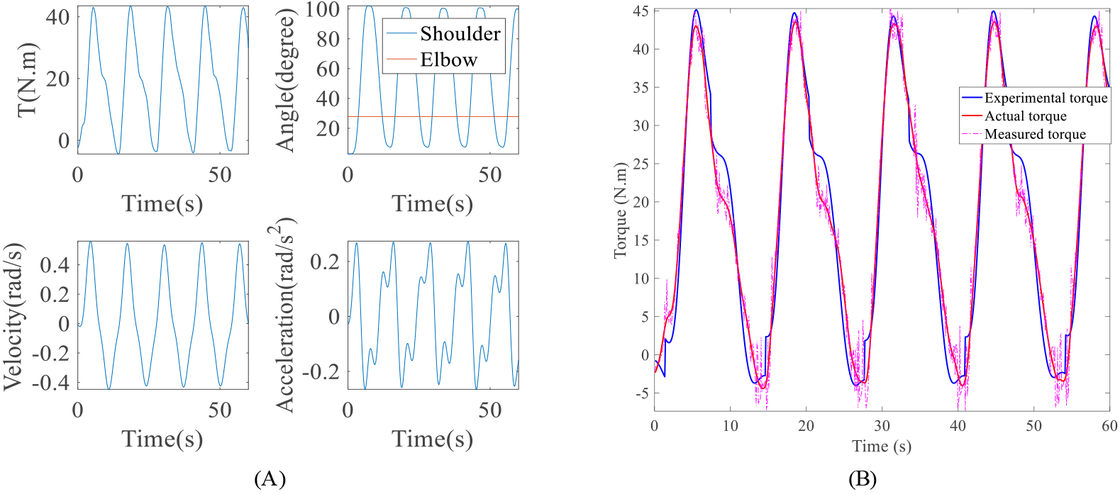
In Figs 6B, 7B and 8B, the pink dotted line is the actual HRC torque without filtering, the red curve is the actual HRC torque after filtering, and the blue curve represents the experimental HRC torque. The torque RMS of experiments 4–6 is shown in Table 2. The torque RMS of elbow joint is 0.9159 N.m, the maximum of actual torque measured in experiment 4 is about 10.0 N.m, and the error is 9.0%. The torque RMS of experiment 5 is 3.6425 N.m, the maximum of actual torque measured in experiment 5 is about 44.0 N.m, and the error is 8.3%. The torque RMS of experiment 6 is 2.7001 N.m, the maximum of actual torque measured in experiment 6 is about 37.0 N.m, and the error is 7.3%. The error of shoulder joint is kept within 10%.
In the teaching mode of FLEXO-Arm, the robot drives the human arms to move together, and the shoulder and elbow joints move freely. The joint angles are recorded for one minute and the obtained angular velocities and accelerations of the joints are calculated by the differential method. The data
Torque RMS of the comparison of the robot and HRC
Torque RMS of the comparison of the robot and HRC
Experiment 6: The elbow joint of the robot is fixed at 85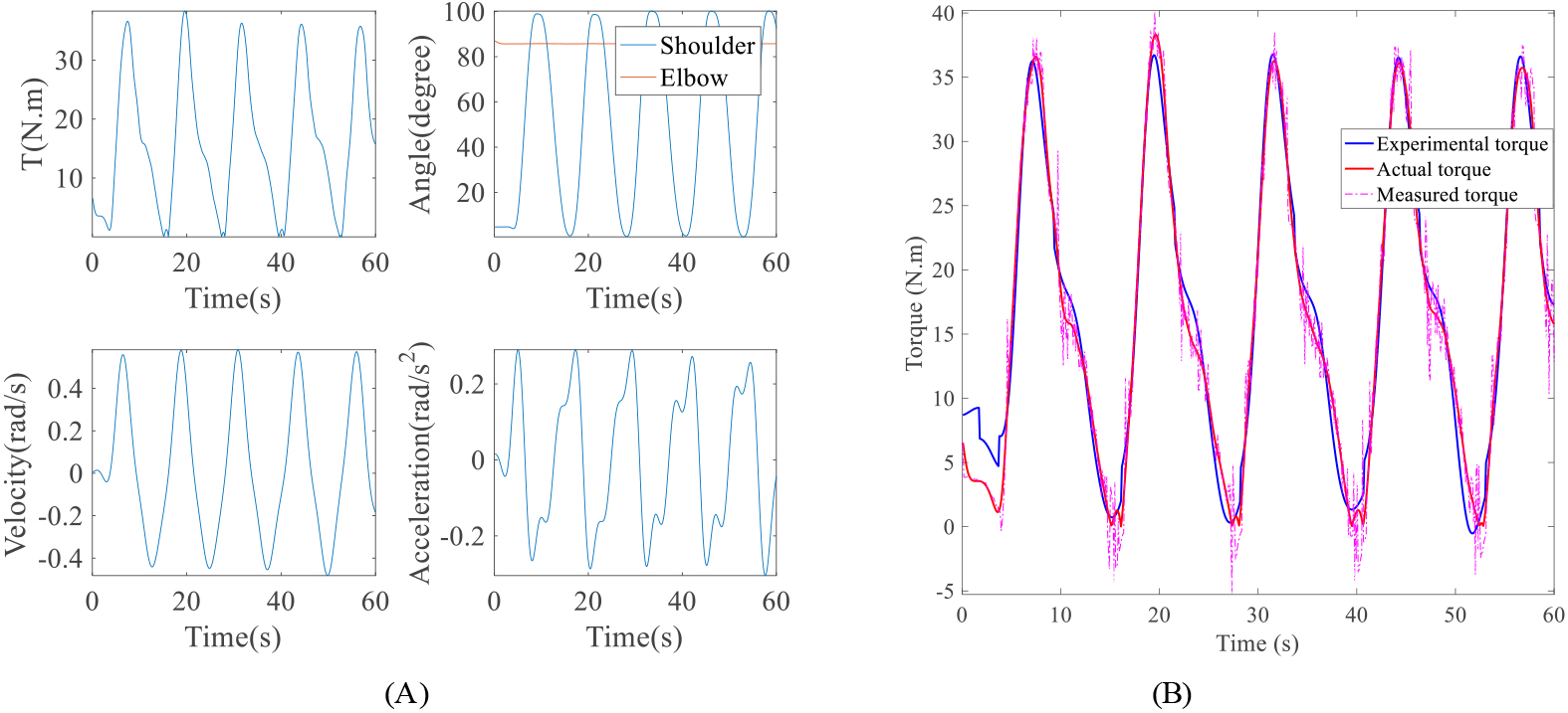
Comparison of the robot torque and HRC torque. A. The elbow torque. B. The shoulder torque.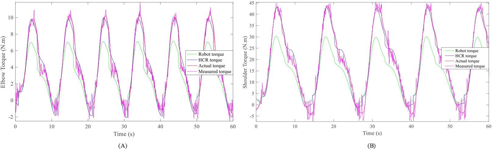
This paper proposes a method for the modeling and analysis of HRC dynamics of upper limb rehabilitation robots, and solves and compares the HRC torque and the robot torque of a 2-DOF upper limb rehabilitation robot (FLEXO-Arm). The errors of HRC and robot dynamic parameters identification are both around 10%, and the robot’s torque RMSs are more than twice HRC. The results show the effectiveness of the HRC dynamics proposed in this paper and the HRC dynamics should be analyzed for the analysis of upper limb rehabilitation robot dynamics, not just the robot dynamics or human dynamics.
Upper limb rehabilitation robots can be classified into end-effector-base and exoskeleton robots. The end-effector-base robot traction by connecting the end-effector of the robot to the human hand. For the dynamic modeling of the end-effector-base robot, the interaction force between the human hand and the end-effector of the robot is collected, and the impedance model of the human arm is established. The torque of each joint can be solved by the robot’s Jacobi equation and the human-robot interaction force [23, 24]. The exoskeleton robot is designed by imitating the joints of human arm based on the bionic principle, so that it has a similar kinematic structure with human arm. The exoskeleton robot is attached to the human upper limb at multiple locations, which makes the force difficult to measure [1]. Hence, many researchers established the equivalent mechanism of the human arm and analyzed the kinematics and dynamics of the model, which provided a reference for the exoskeleton dynamics model [14, 15]. Due to the complexity of upper limb movement, many researchers ignored the influence of the human arm when analyzing the dynamics of exoskeleton robots. In this paper, the HRC dynamics is proposed, which takes the human arm and robot as a whole. The method is not only applicable to passive motion of the rehabilitation robot, but also to assistive motion. The assistive control strategy will be completed in the follow-up work.
Conclusions
This paper analyzes the human-robot interaction and proposes that the HRC torque is equal to the robot torque plus the human arm torque. The HRC torque and the robot torque of a 2-DOF upper limb rehabilitation robot (FLEXO-Arm) are solved by Lagrange equation and parameter identification. The root mean square is used to evaluate the accuracy of the HRC torque and the robot torque calculated by the parameter identification, and the error of both is about 10%. Moreover, the HRC torque and the robot torque are compared with the actual torque measured by torque sensors. The error of the robot torque is more than twice the HRC. Therefore, the HRC torque is more accurate than the actual torque. The results show the effectiveness of the HRC dynamics proposed in this paper and the HRC dynamics should be analyzed for upper limb rehabilitation robot dynamics, not just robot dynamics or human dynamics.
Footnotes
Acknowledgments
The authors gratefully acknowledge the financial support by th National Key R&D Program of China (2018YFB1307200), and the National Natural Science Foundation of China (61803265).
Conflict of interest
None to report.