
Abstract
BACKGROUND:
Antennas for the microwave imaging system are large which results in higher radiation, manufacturing cost, poor radiation characteristics and it will be difficult to locate on breast tissues.
OBJECTIVE:
We propose a wearable ultra-wide band antenna for use in the diagnosis of breast cancer bio-medical applications.
METHODS:
The antenna has been fabricated on 1.6 mm FR4 substrate with a dimension of 28
RESULTS:
The maximum simulated efficiency was ranging from 80 to 84% in the desired operating frequency. The maximum Specific Absorption Rate of the proposed antenna was 0.98 W/Kg. Therefore, the proposed UWB antenna could be the right structure for breast cancer diagnosis in terms of SAR. The antenna was found to have a substantial radiation efficiency of around 78%–84% in the desired operating bandwidth. The overall realized gain of the proposed UWB antenna was seen ranging from 1.8–4.2 dB which is sufficient for bio-medical applications.
CONCLUSION:
The breast phantom was modeled for the validation of the performance of the antenna and SAR was analyzed. The value of SAR of the designed antenna was observed at about 0.98 W/Kg, which is suitable for medical applications.
Introduction
Two decades ago, cancer patients had no warning signs or symptoms until the disease had progressed to an advanced stage. As a result, early diagnosis of cancer is essential in order to increase the chances of a successful oncologic therapy. Electromagnetic (EM) or sound waves interaction with human biological fluids are used in the majority of diagnostic testing, but not all of them function in the same range of frequencies. X-rays are extensively utilized, irrespective of the numerous types of clinical screenings, since they help reliable disease diagnosis. They release high-energy electromagnetic radiation, and ionizing during radiation has been shown to be useful for a variety of medical applications, it can also have negative consequences [1, 2, 3]. As a consequence, its usage in biological testing increases the likelihood of causing irreversible alterations in tissues, which will lead to cell mutation till death. While other methods like Magnetic Resonance Imaging (MRI) may offer support in early detection, the technique has some drawbacks, including higher costs, unavailability to a significant number of diseased people, and incorrect detection for smaller size tumor cells resulting in a shorter distance between the MRI slices and the target. As a result, these approaches can’t be used frequently. Furthermore, breast-related disorders require examination on a regular basis to ensure the welfare of the patients. Microwaves or Microwave Imaging (MI) approaches have proven to be reliable after numerous researches as ionization and breast contractions could be avoided. Furthermore, microwave breast cancer identification may identify lesions with smaller diameters. It is less expensive than most other screening tests like MRI and radiation therapy. Microwaves have a wide range of medical applications and are, amongst other things, used as a tumor detection diagnostic tool.
Radiofrequency is used in the production of medical pictures, which are based on dielectric discrepancies between normal and infected tissues due to the interactions of EM waves with bio-molecules [6]. The relation behind them is based on dielectric characteristics that are interconnected to the liquid characteristics of various biological components such as bones, lipids, and muscles [7]. Electromagnetic radiation is capable of entering biological tissue in a very effective manner and maintaining a reasonable absorption between the ranges of 1 GHz to 10 GHz, while higher frequencies above 10 GHz could disperse impacts on the surface of the skin [8, 9]. As a result, electromagnetic evaluation of human tissues may be used for the detection of initial stage breast cancer detection.
MI technologies, which employ the microwave radar method, are seen as a promising tool. It is simpler to distinguish between cancer and normal cells with the help of this technique. In a non-ionizing approach, lower amounts of radio waves from mobile devices are spread into the breast tissue. It is indeed a low-cost, non-ionizing device that is appropriate for routine inspections with capability for identification of extremely tiny cancers [10].
The UWB microwave imaging process is a non-ionizing, low-cost technology that has found extensive use in recent decades for the early identification of malignant tumors [11]. UWB is a narrow range communication technology that sends out brief pulses of data. It provides the appropriate image quality as well as the facility of excellent breast tissue penetration. The broad feature of UWB electromagnetic waves helps getting high-quality pictures and the required penetration is achieved through use of Ultra-wideband signal with a spectrum lower than 10 GHz [13].
UWB MIMO antennas are commonly utilized in volume-restricted and wideband applications. It is proposed that such a UWB MIMO antenna be developed and utilized for medical health care applications, specifically for breast ultra-wideband MIMO application which is used for the detection of tumors [14, 15]. The changes in the material used for the substrate and the thickness of the substrate, according to research, can help get a substantial increase in system performance when the dielectric constant (r) varies [16]. It is less damaging to the human body and so several research articles focus on the fabrication of microstrip patch antennas for microwave imaging systems. Wearable or non-wearable microwave patch antennas for on-body applications are possible [17]. Ruan et al. [18] show the features and morphological behavior of breast cancer. The different types of breast cancer and how to diagnose them using various models are also depicted.
From the literature it was found that antennas for the microwave imaging system are significantly bigger in overall size which results in higher radiation, manufacturing cost, poor radiation characteristics and it will be difficult to locate on breast tissues. We try to solve problem of the overall size of the antenna by minimizing the size of our antenna to 28
The wearable ultra-wideband antenna referred to in this article has been designed for diagnosing breast cancer bio-medical applications working in the frequency range from 2 GHz to 12 GHz with 2: 1 Voltage Standing Wave Ratio (VSWR) with better radiation performance. Further, the SAR analysis has been done to validate the antenna performance in a real-time environment.
Design methodologies
Conventional antenna design
The front and back views of the conventional method are shown in Fig. 1a and b respectively, along with the specifications of the sizes. The conventional antenna was designed to cover the frequency spectrum from 3.22–11.92 GHz. The size of the antenna is around 30
Conventional ultra-wide band antenna design: a. Front view, b. back view.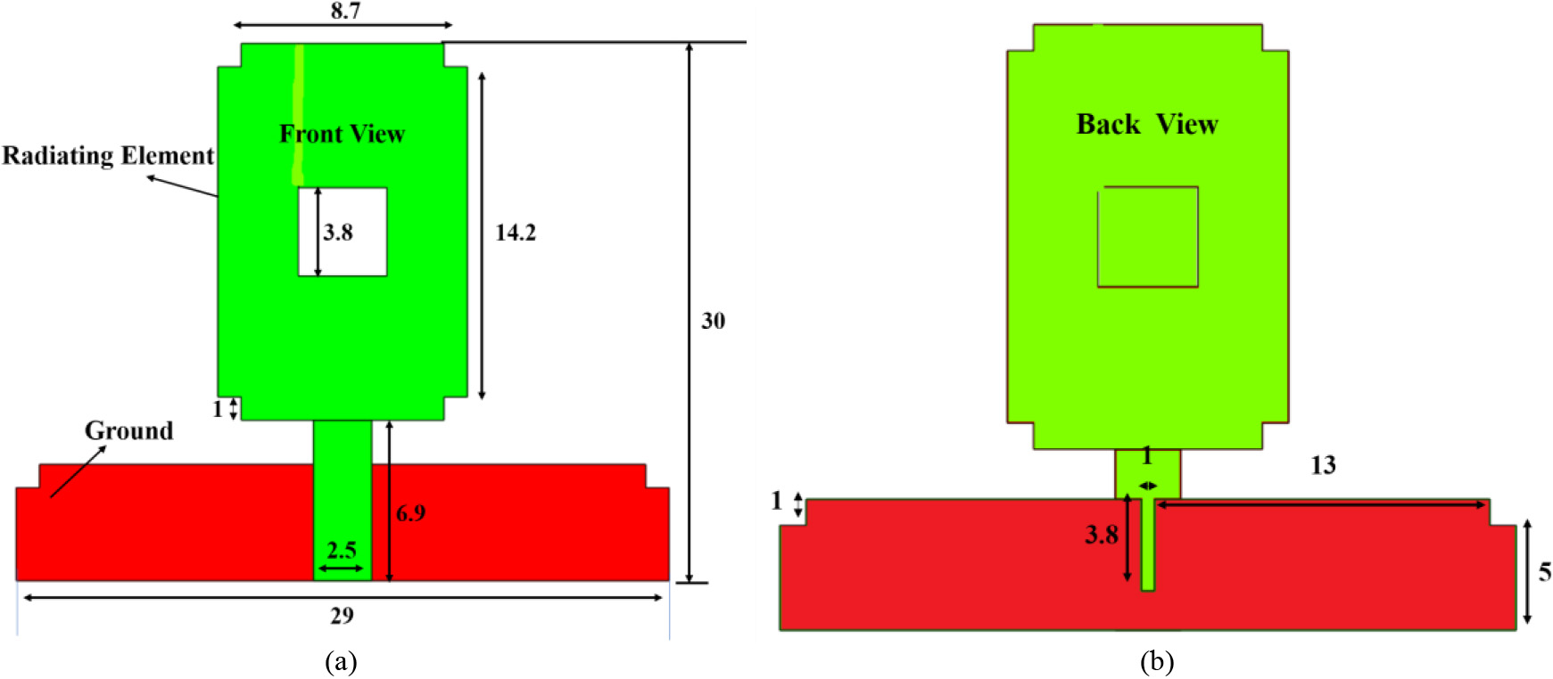
The structure of the proposed antenna was formed by designing a hexagonal-shaped patch antenna on the top surface of the 1.6 mm FR4 substrate and is fed by a 50-
The proposed UWB antenna is meant for radiation and receipt of information covering the entire spectrum from 3 GHz to 13 GHz as shown in Fig. 2b. For good impedance matching through the larger spectrum, the defected ground structure (diamond shape) was exploited. All the dimensions of the proposed design were confirmed by parametric study and optimization.
a. Proposed ultra-wide band antenna, b. proposed antenna simulated and measured reflection co-efficient (
The suggested antenna was manufactured and tested for the evaluation of performance efficiency. The reflection coefficient analysis of the suggested antenna design in relation to simulation and experimental data is shown in Fig. 2b.
Figures 3 and 4 show the evolution of the suggested antenna design and its results. To start with, the patch with the rectangular shaped ground was designed and named as (Ant a). This is shown in Fig. 3a. However, this structure was found to be unable to provide the UWB operation as shown in Fig. 4. Hence, the top edge of the ground was reduced and named as (Ant b) as shown in Fig. 3b and the reflection coefficient of this structure (Ant b) is depicted Fig. 4. Still, it did not produce the required bandwidth; hence Ant C was evolved as shown in Fig. 3c. In order to improve the reflection coefficient of the proposed design structure, the design structure of both Ant b and Ant c were combined (as depicted in Fig. 3d). This was found to have the ability to cover the desired bandwidth from 3 GHz to 13 GHz with
Design evolutions of the proposed antenna: a. Ant a, b. Ant b, c. Ant c, d. Ant d.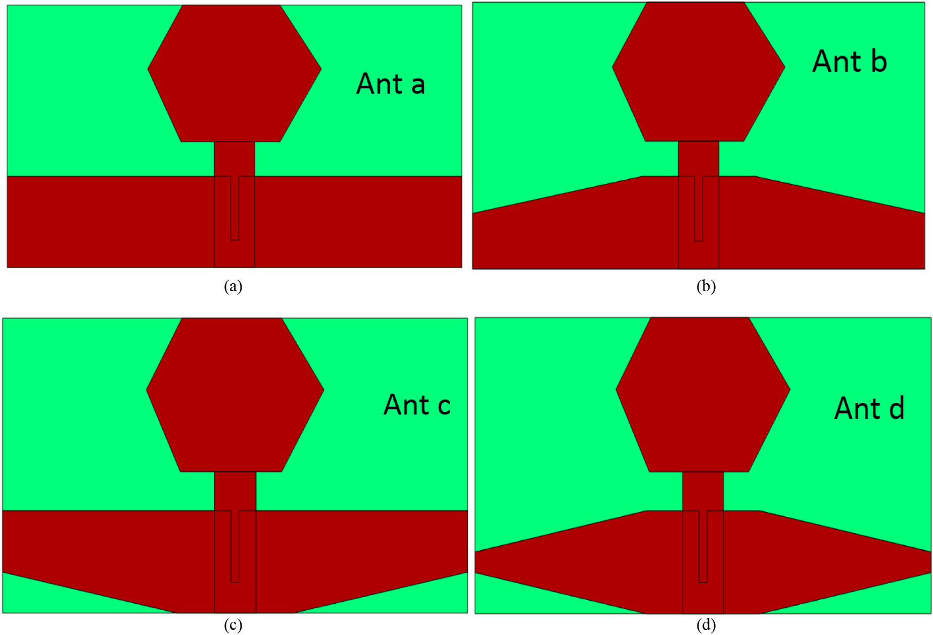
Analysis of reflection co-efficient of the proposed antenna structures Ant a–Ant d.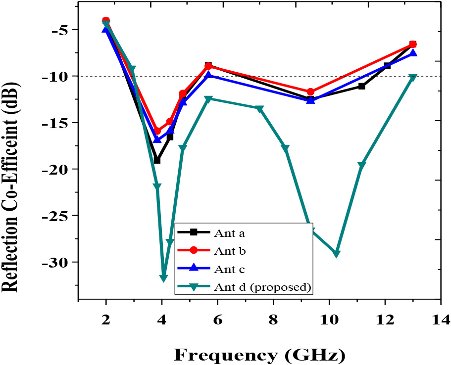
In this paper, ADS version 2021 developed by Keysight Technologies was used for the simulation of the proposed antenna structure for use in breast cancer detection. The surface current distribution of the antenna considered in this article was meant to evaluate its resonance characteristics at 5 GHz, 8 GHz, and 11 GHz. This is shown in Fig. 5a–c. During the resonance at 5 GHz, the maximum current was observed at the center surface of the radiating element (pentagonal shape) as shown in Fig. 5a. During the resonance at 8 GHz, the current distribution was seen getting lower and maximum at the lower part of the antenna. This is shown in Fig. 5b. At a higher frequency (11 GHz), the current drop was larger and minimum at bottom of the radiating patch. This showed the maximum area of the radiating element as responsible for the lower resonance and bottom surface making the antenna resonating at higher order frequencies, as the simulation result depicted in Fig. 5c.
Surface current distribution of the proposed antenna: a. 5 GHz, b. 8 GHz, c. 11 GHz.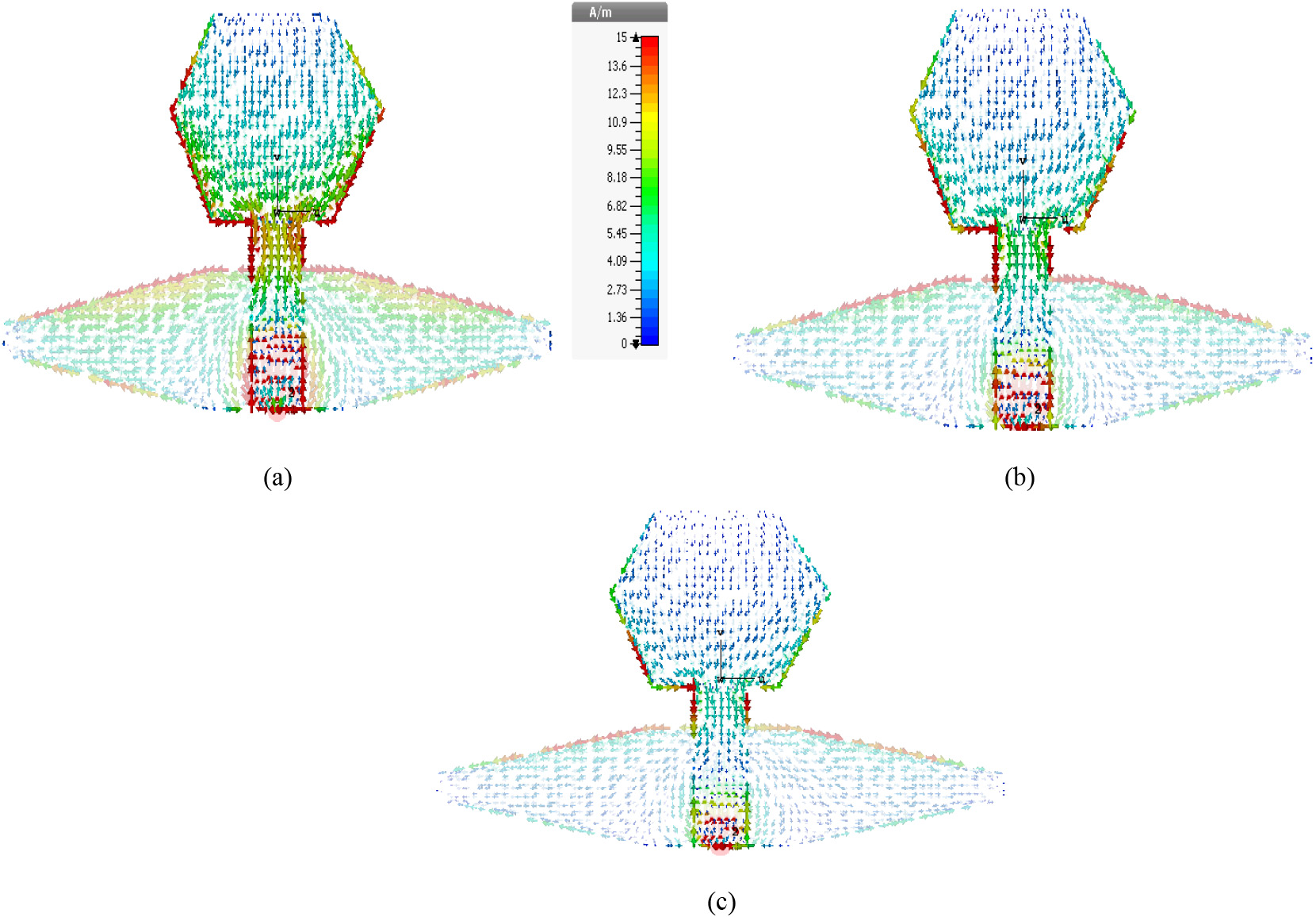
3D radiation pattern of the proposed antenna: a. 5 GHz, b. 8.5 GHz.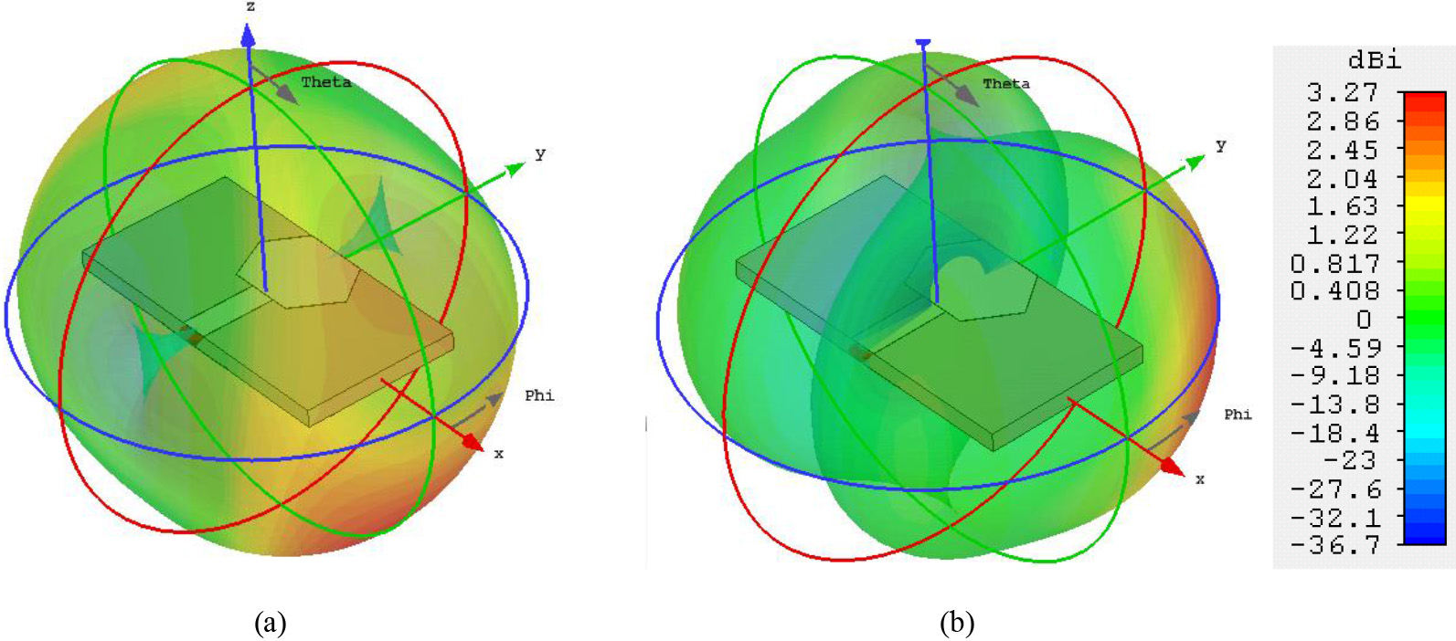
The three-dimensional (3D) radiation patterns of the proposed ultra-wide band antenna at 5 GHz and 8.5 GHz is shown in Fig. 6a and b respectively. The maximum radiation is seen taking place along the direction of the patch (Phi direction), revealing that radiation coming out of the antenna will not affect the patient’s tissue. The gain observed in the resonance was around 3.7 dBi maximum.
Figure 7a and b show the efficiency and gain of the proposed antenna with respect to simulation and experimental results. The maximum simulated efficiency was observed ranging from 80 to 84% in the desired operating frequency, as illustrated in Fig. 7a, clearly showing the proposed antenna as the best choice for biomedical applications. Similarly, the gain of the antenna ranged from 3–7 dB, as illustrated in Fig. 7b.
Figure 8a through d shows the two-dimensional radiation pattern of the antenna. The antenna showed the unidirectional radiation pattern along the X direction (Co-polarization) as depicted in Fig. 8a and c respectively. The antenna showed the unidirectional radiation pattern along the Y direction (Cross-polarization) as depicted in Fig. 8b and d respectively.
Figure 9a–d shows the measured radiation pattern along the X direction and Y direction. This proves that the proposed antenna has highly unidirectional radiation out of the human body.
Table 1 shows the electrical properties of breast phantom model according to the standard specifications given in Afifi et al. [7] and Fear et al. [8].
Electrical properties of the breast tissues
Simulation and measurement of the proposed UWB antenna: a. Efficiency, b. gain.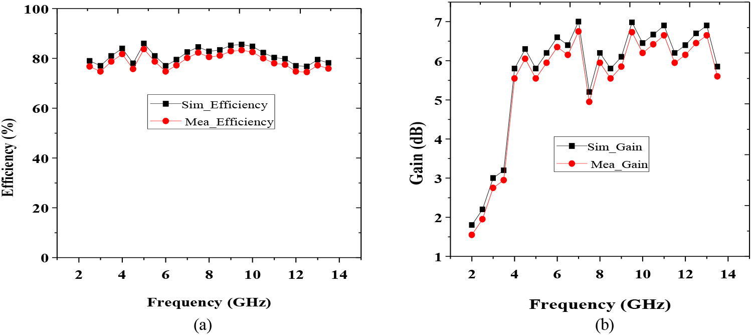
2D Radiation pattern of the proposed antenna (simulation): a. Co-polarization at 4 GHz, b. cross polarization at 4 GHz, c. co-polarization at 8 GHz, d. cross polarization at 8 GHz.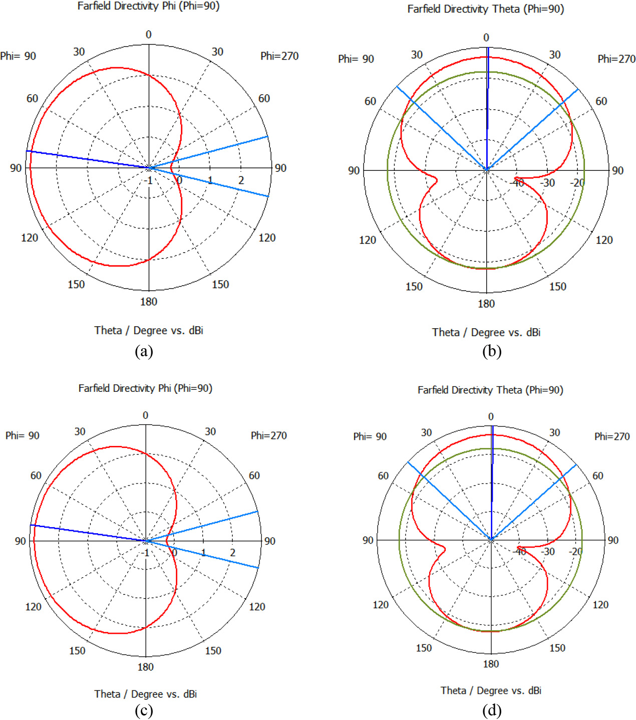
2D Radiation pattern of the proposed antenna (measured): a. Co-polarization at 4 GHz, b. cross polarization at 4 GHz, c. cross-polarization at 4GHz, d. cross polarization at 8 GHz.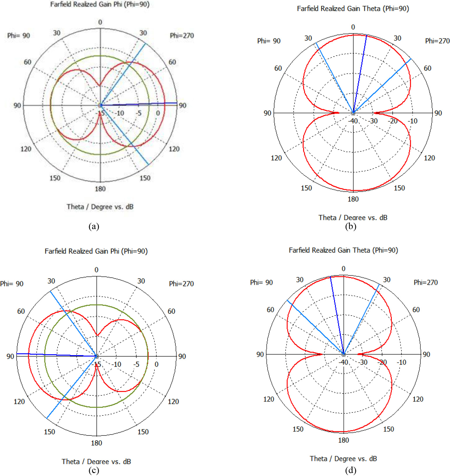
S-Parameter analysis of the proposed antenna with respect to different conditions (free space, normal breast region and defective breast region).
SAR analysis of the proposed antenna: a. 4 GHz, b. 7 GHz, c. 9 GHz, d. 11 GHz.
A phantom is made up of a 3D grid of regions of interest with some threshold values combining volume and pixels called voxels, each with its own physical characteristics depending on the tissue type represented. Anatomically correct numerical breast phantoms are created using a similar procedure (e.g. [23, 24, 25]). Breast MRIs in healthy women provide a map of typical tissue types across the breast volume. They are preferred considering their offer of tomographic images, which are required for the creation of 3-D models of the breast, and pixel intensity linked to biological tissue type. While segmenting tissue sections, MRI image processing can remove noise and artefacts. For making tiny volume and pixel (voxel) values that are homogeneous in all three dimensions, interpolation is typically utilized. When it comes to the modus operandi of the allocation of the characteristics to each threshold value in the breast interior, there is a lot of diversity among methodologies. A linear mapping was used for the assignment of dielectric properties to each voxel at each level, with three levels spanning the properties of adipose tissue: one level for transitional tissue (a heterogeneous mix of adipose and fibro glandular tissue), and three levels for fibro glandular tissue, with three levels spanning the properties of adipose tissue. The voxel intensities had to be segmented and the linear mappings of each level had to be constructed. As shown in a report by the American College of Radiology [27], voxel-based numerical phantoms such as those depicted by a report from the University of Wisconsin [26], can be transformed for use in commercial simulation systems and for the use of the two-component Gaussian mixture.
The following procedure was used when importing a numerical breast phantom from the University of Wisconsin repository into Computer Simulation Technology (CST) Microwave Studio:
Material numbers for up to 256 different materials were kept in a volume and pixel (voxel) file with their names tagged. Creation of a material file that included among other things, material numbers, material names, non-dispersive dielectric properties, and thermal parameters. Creation a material file with material numbers, names, non-dispersive dielectric characteristics, and thermal parameters, among other things. After importing the voxel model into CST Microwave Studio, loading and execution of the macro to redefine the different material parameters, and then complete.
The proposed antenna (numerical phantom) is kept on the skin layer of both normal breast and defective breast tissues for a study of the performance of the preferred structure. Figure 10 shows the S parameter results of the proposed antenna in free space, with normal tissues as well as in the skin layer of malignant breast phantom. The performance of the antenna was good in all three conditions, especially in the presence of malignant, the reflection coefficient is slightly different from the other two conditions, as illustrated in Fig. 10.
The breast phantom was modeled for the evaluation of SAR of the proposed UWB antenna, considering radiation coming out of the antenna could influence the human tissues and result in an unwanted disturbance during the diagnosis. The proposed antenna kept on the phantom model is shown in Fig. 11a–d, and it helps in the observation of the SAR of the antenna at 4 GHz, 7 GHz, 9 GHz, and 11 GHz. The designed antenna structure meets the specification provided by FCC for SAR (less than 1.6 W/Kg). The maximum SAR of the proposed antenna is 0.98 W/Kg. Therefore, the proposed UWB antenna could be considered as the appropriate structure for breast cancer diagnosis in terms of SAR.
Table 2 shows the performance comparison of the proposed wideband antenna breast tumour detection applications. Lalitha et al. [14] provide a very narrow bandwidth operation for tumor diagnosis. But nowadays, only UWB antennas find extensive use in medical applications. In other works [15, 16, 17], despite the ability of the antennas to cover an ultra-wideband for tumour diagnosis, the overall sizes of the designs are comparatively larger than the proposed antenna. The antenna described in this article can be a vibrant candidate for biomedical applications.
Performance comparison of the proposed antenna design with existing designs
The ultra-wide band meant for use in breast tumor diagnosis has been successfully investigated in this article. The antenna covers the spectrum from 3 GHz–13 GHz, in
Footnotes
Acknowledgments
The authors thank their friends at the KCG College of Technology and their family members for the preparation of this paper as well as their research supervisor for the constant support for this research.
Conflict of interest
None to report.