
Abstract
BACKGROUND:
The limited number of hip prostheses users makes it less feasible to conduct amputee tests for prosthesis development in the clinic, which restricts the development efficiency of the intelligent prostheses.
OBJECTIVE:
This study proposes a hip disarticulation prostheses test system (HDPTS) to supplement the amputee tests for hip disarticulation prosthesis (HDP) evaluation, which would potentially facilitate the prosthesis evaluation safety and development efficiency.
METHODS:
The hip trajectory of an individual with normal gait was acquired and reproduced by calculating the corresponding movement joint angle of a manipulator. Then, an HDP was fit on an amputee and on the HDPTS respectively to obtain the hip and knee joint angles of the HDP during walking. Comparing the root mean square error (RMSE) of the expected and planned trajectory, the joint angles between the amputee test and HDPTS test, to verify the feasibility and accuracy of the HDPTS for prosthesis evaluation.
RESULTS:
The RMSE between the expected and planned trajectory value was less than 1.20 mm (
CONCLUSION:
The HDPTS was found accurate in hip trajectory reproduction and feasible in gait simulation for the prosthesis evaluation, which could potentially supplement the amputee test for prosthesis design thus improving prosthesis test safety and development efficiency.
Keywords
Introduction
Hip disarticulation prosthesis (HDP) is a kind of prostheses used for amputees with hip disarticulation or hemipelvectomy. Around 1%–2% of the lower limb amputees suffered hip disarticulation or hemipelvectomy [1, 2], among which more than half refused to use prostheses in daily life due to the inconvenience such as less flexibility, low stability, heavy weight and high energy consumption [3, 4]. For the development and validation of the newly designed HDPs, repetitive tests on human subject are required to evaluate the gait, metabolic cost and psychological acceptance [5, 6, 7]. However, the limited number of the HDP users, the safety risks, ethical considerations as well as low reproducibility of the human test make it less feasible and reliable to conduct HDP test in real situation, which directly restricted the development efficiency of HDPs.
A hip disarticulation prostheses test system (HDPTS) may avoid these disadvantages of human test. The HDPTS is a specially designed platform that can drive a prosthesis to walk for prosthesis evaluation, instead of recruiting an amputee to fit the prosthesis to walk for prosthesis evaluation. An efficient prosthesis test system is required to simulate normal/hazard conditions without safety issues, work continuously for mechanical durability test, optimize the control algorithm of the prosthesis via repeated measurements and acquire indirect parameters such as joint torque through build-in sensors [8]. The standardized test process and quantitative parameters provided by the test system will facilitate the design accuracy and efficiency for HDPs.
Previous studies have made attempts on the development of prosthesis test system (PTS). Kim and Oh designed an above-knee prosthesis test system with three degrees of freedom (DOFs, horizontal, vertical and rotational movement) to assess the prosthetic knee joint position and velocity, while the influence of gravity center change was ignored in their system [9]. Cao et al. developed a prosthesis knee test system which assisted studying speed adaptive control method for a prosthetic knee via 1) simulated velocity changes and detected corresponding knee angles 2) simulated hip joint to drive prosthetic knee and evaluated the swing flexion [10]. Davis et al. developed a below-knee prosthesis test system to optimize the ground reaction force (GRF). The system followed able-bodied hip and thigh trajectories, then modified the reference inputs to minimize the error between the GRF of the system and that of the able-bodied gait. Results showed a 62% decrease in the GRF error, which demonstrated the compensation for the prosthesis of the developed system [11]. Richter et al. proposed a PTS that simulated the movement of the hip joint in two DOFs on the sagittal plane for testing prostheses knee joint [12]. Yilmaz et al. developed an above-knee PTS that regenerated the vertical displacement of the hip joint and the angular motion of the thigh [13]. Yu et al. proposed a PTS to evaluate the gait symmetry of a prosthetic limb by comparing the stride length and joint angle between the sound side and affected side [14]. Vahid et al. used motors to simulate the hip and thigh movement to test a prosthesis leg with three DOFs. Two robust model reference adaptive impedance controllers were proposed for a natural walking simulation. The results confirmed the good tracking of joint displacements and velocities, and reasonable control of the controller [15]. Li et al. developed a HDPTS using a manipulator which was reported feasible and accurate for hip prosthesis simulation and evaluation, they also pointed out that the reproduction of pelvis trajectory to evaluate the lower limb movement may neglect the relative movement between the pelvis and the hip [16]. Previous prosthetic test systems that focused on the knee or ankle prostheses test [8, 9, 10, 11, 12, 13, 14, 15] were not applicable to the hip prostheses test, as the hip was regarded as a fixed or semifixed component in these systems and such structure were not compatible with a hip prosthesis. Furtherly, most of these systems used motors to drive the prosthesis to walk, while the limited space between the hip joint and the attachment point does not allow the motors assembly in the HDPTS. Instead of using motors as the active joints, the manipulator provided sufficient space for prosthesis assembly and movement hence would potentially be applied in hip prosthesis test system.
Therefore, this study proposes a HDPTS designed with a manipulator to supplement the amputee test for HDP evaluation. The hip trajectory was simulated to compare with the expected trajectory, thus determine the trajectory accuracy of the HDPTS. The kinematics of the prosthesis on the HDPTS were obtained to compare with the target value, thus verifying the feasibility of prosthesis test for the HDPTS With the HDPTS, the amputee involved test could potentially be supplemented or even replaced during prosthesis design, thus improving the prosthesis test safety and prosthesis development efficiency.
Methods
Design of HDPTS
The design of the HDPTS is shown in Fig. 1. A six-axis manipulator was used to reproduce the trajectory of rotation center of hip joint (greater trochanter) during walking. The D-H parameters of the manipulator are shown in Table 1. The real-time instrumentation and control were realized through the RT-SIM system (Beijing Links Tech Co., Ltd.). A built-in encoder was assembled in the manipulator to detect the end posture in real time. A lifting column with a base was connected to the manipulator for the height adjustment to adapt to different prostheses. The HDP can be bolted to the end of the manipulator for evaluation. A treadmill was used for level walking of the test prosthesis. A flexion spring was used to limit the range of motion and maintain stability of the system during test.
D-H parameters of each axis of the manipulator
D-H parameters of each axis of the manipulator
Design of hip disarticulation prostheses test system.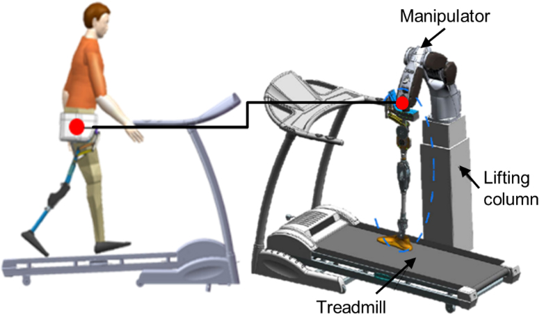
The trajectory planning flowchart of HDPTS is shown in Fig. 2. It was divided into a hip trajectory acquisition stage and a hip trajectory reproduction stage. For the trajectory acquisition, the motion of the great trochanter of a subject was acquired, which formed the targeted trajectory of the manipulator through spline curve trajectory planning. Then, the acquired data and the center offset coordinates were synthesized and input into the manipulator module. For the trajectory reproduction, the homogeneous matrix was obtained through the D-H parameters and the rotation matrix of the manipulator. Then the collected data was input to obtain the coordinates of the end posture of the manipulator, and further calculated the joint angle of each axis through the inverse kinematics of the robot.
Trajectory planning flowchart of hip disarticulation prostheses test system.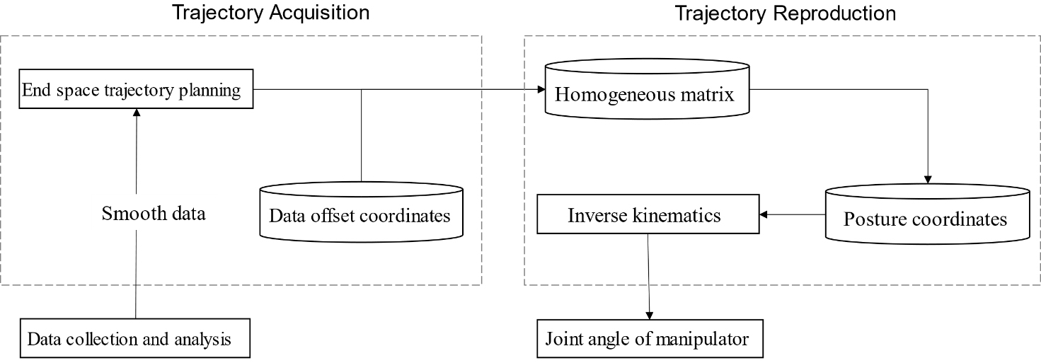
A VICON motion capture system (Vicon Motion Systems Ltd, Oxford, UK) was used to capture the position information of the greater trochanter of a subject (male, 29 years, height 173 cm, weight 66 kg) with normal gait. An amputee was not recruited for acquiring the coordinates of the great trochanter in this procedure because the severe asymmetry of amputee gait patterns could affect the accuracy of the system design. According to our pilot study, gait symmetry index of the subject with hip amputation and without amputation were
Diagram to obtain joint angles of the manipulator.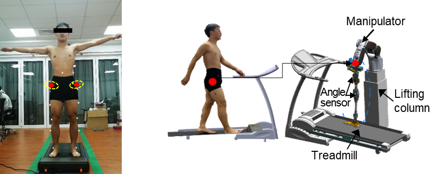
After obtaining the coordinates of great trochanter, a second-order Butterworth Filtering method was used for data filter and smoothen with the cut-off frequency of 50 Hz, avoiding the sudden change of the speed and the acceleration. Then, the trajectory planning was carried out in the terminal operation space, considering the acquired position coordinates of the great trochanter were a series of points with relatively simple inverse kinematics. The motion law adopted polynomials, cycloids and modified trapezoids, which could plan the trajectory between two points along the path effectively in the operating walking speed. The cubic polynomial planning method was used for the trajectory planning, since cubic polynomial spline trajectory obtained the global minimum acceleration which improved the tracking accuracy and reduced the manipulator vibration [17]. Furtherly, the joint angle of the manipulator in each axis can be obtained through inverse kinematics. Based on the cubic polynomial trajectory planning, the position during the moment
Where
According to the position and speed continuous boundary conditions, the following equation can be achieved:
Where
After the trajectory planning of the position coordinates, the data was imported into the six-axis manipulator to acquire the angle of each joint through the D-H method [18]. The homogeneous matrix of the end posture of the manipulator was solved through the three-dimensional coordinate values of the great trochanter. The homogeneous matrix was composed of a rotation matrix, a position matrix and a unit vector, namely
According to D-H parameter of the manipulator:
Where
Model was established in Matlab to obtain joint angles of the manipulator, then input to the RT-SIM manipulator control system to control the manipulator, the procedure was shown in Fig. 4. Compare the expected value of the three-dimensional coordinates of the simulated trajectory with the actual value to calculate the root mean square error (RMSE) for analysis.
Trajectory planning procedure for the hip disarticulation prostheses test system.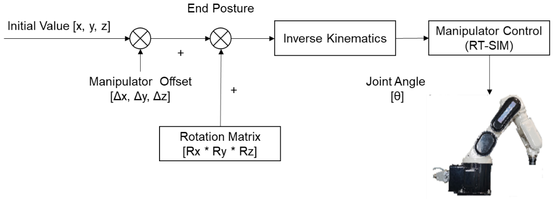
Comparison between subject test and system test.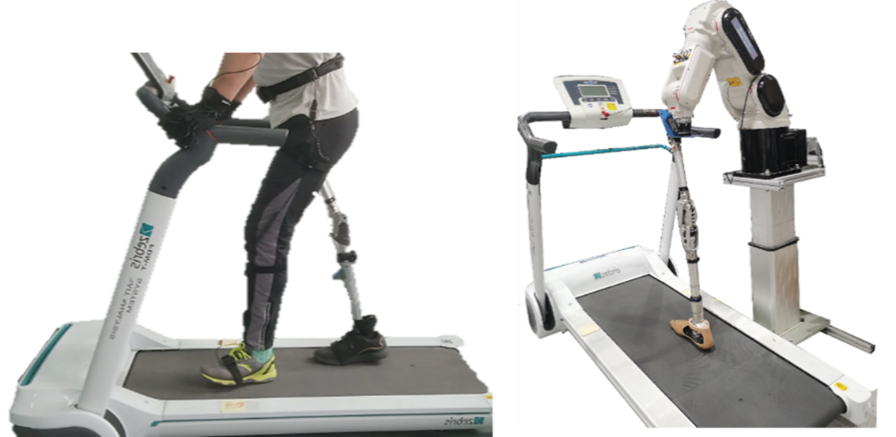
Subject test
The procedure of subject test and HDPTS test is shown in Fig. 5. An amputee (male, 57 years, height 171 cm, weight 63 kg)) fitted with an HDP (7E7 prosthesis hip joint; EBS3R60 prosthesis knee joint; 1C40 prosthesis ankle joint; Ottobock Healthcare, Germany) was recruited. MyoVIDEO™ module (Myoresearch
Trajectory of hip vertical displacement.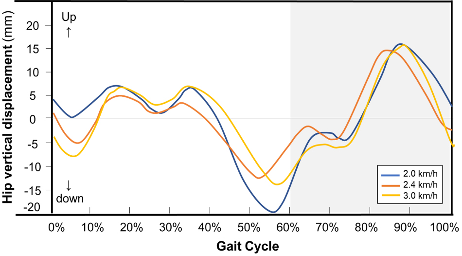
After subject test, the tested HDP was doffed from the amputee and attached to the end of the manipulator of the HDPTS. The lifting column was adjusted to keep the prosthetic foot just contact the treadmill. MyoVIDEO™ module were activated to record the angle of the hip and knee joints during movement of the prosthesis. Then, the treadmill was started at the same speed of the subject test, meanwhile the manipulator simulated the greater trochanter motion trajectory which was reproduced to drive the prosthesis leg to walk on the treadmill. One test session lasted for 1 minute and each session repeated for 3 times with 2-minute stop in between. The average value of ten gait cycles was calculated as the simulated hip and knee joint angle. The RMSE of the simulated joint angle value and the targeted joint angle value were calculated and compared to verify the feasibility of prosthesis test for the HDPTS.
Results
Trajectory planning
The trajectory of hip vertical displacement is shown in Fig. 6. The hip vertical displacement ranged within 35 mm at different walking speeds. There were two typical move-up stages and two move-down stages at each gait cycle (GC). The hip moved down to the lowest at around 5% GC (loading response) and 61% GC (pre-swing), both of which occurred at the double stance phase. The hip moved up to the highest at around 32% GC (mid stance to terminal stance) and 87% GC (mid swing), both of which occurred at the single stance phase. The vertical displacement at different walking speeds was found following the similar trend with the close amplitudes.
The trajectory of hip lateral displacement is shown in Fig. 7. The hip lateral displacement ranged within 57 mm at different walking speeds. The hip started in the neutral position at initial contact. As the gravity transferred to the right leg, the hip moved to right accordingly, with the rightest displacement of hip occurring at around 25% GC (end of mid stance of the right leg). The hip returned the neutral position at around 47% GC (terminal stance). Then, the hip moved to the left and reached at the most left displacement at around 80% GC (during initial or mid swing). The hip lateral displacement ranged within 41 mm, 49 mm, 57 mm at the speed of 2.0 km/h, 2.4 km/h, 3.0 km/h respectively.
Trajectory of hip lateral displacement.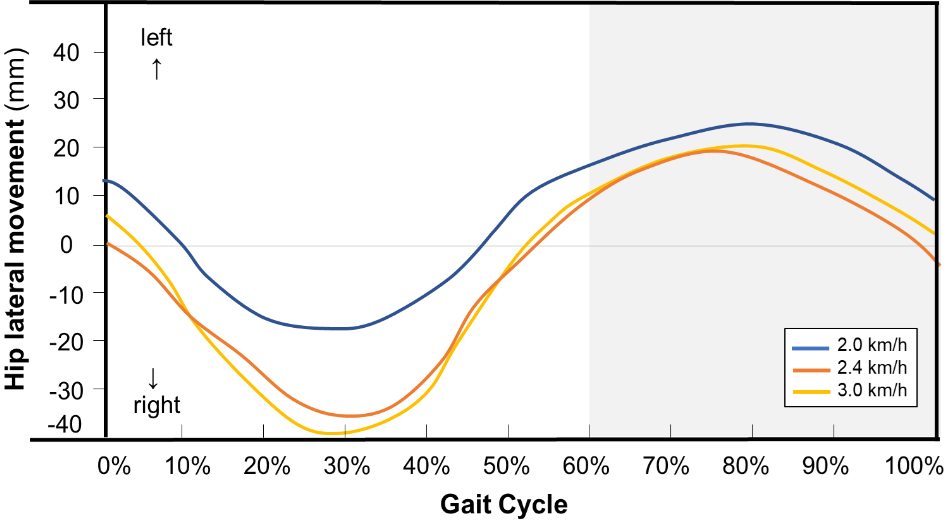
Trajectory of hip forward movement.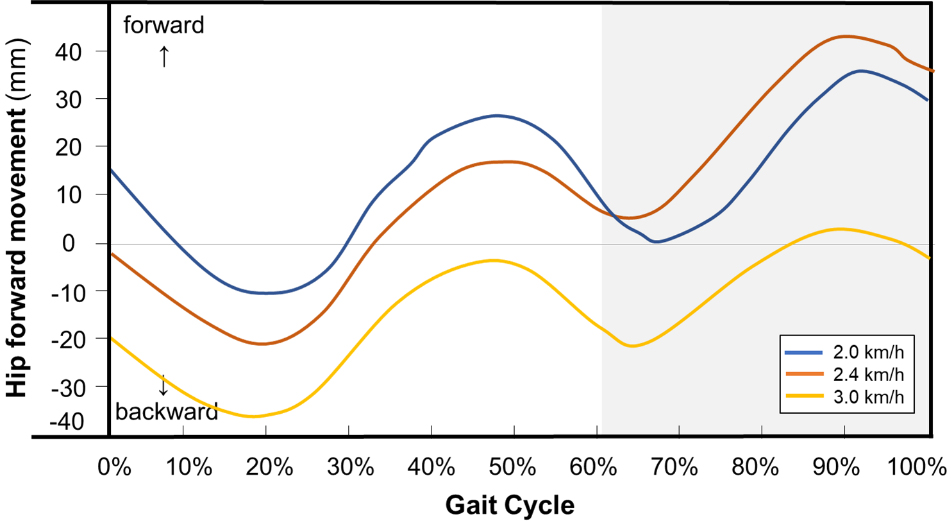
The trajectory of hip forward movement is shown in Fig. 8. The hip forward and backward movement followed the trend of cosine curve. Average 20 mm difference of hip position between the initial contact and the end of terminal swing was observed, this could because that the subject may not always move to the same point after a gait cycle on the treadmill.
The data of trajectory was substituted into the model after smoothing. The key points among an interval of 8 points were selected for cubic polynomial trajectory planning. The time interval was set as 0.01 s, which was in consistent with the time interval of data collection. The RMSE value between the simulation value and target value in the X direction were less than 1.2 mm with the maximum error of 0.11% at the three speeds. The RMSE value between the simulation value and target value in the Y direction were less than 0.8 mm with the maximum error of 0.07% at the three speeds. The RMSE value between simulation value and target value in the Z direction were less than 1.2 mm with the maximum error of 0.19% at the three speeds (Table 2). The low error between the expected and planned hip position in three dimensions verified the accuracy of trajectory planning of the HDPTS.
Root mean square error (RMSE) between simulated hip movement and target hip movement
Test joint angle vs Target joint angle.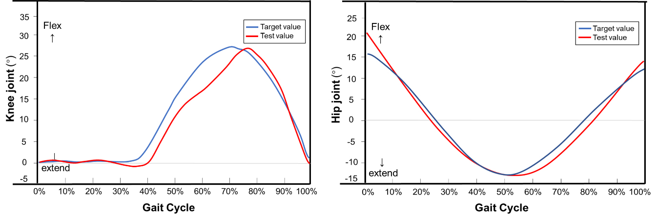
The comparison between the simulation value and target value of hip joint angle and knee joint angle was demonstrated in Fig. 9. For the hip joint, the absolute error and relative error between simulation hip angle (red line, joint angle obtained from HDPTS) and target hip angle (blue line, joint angle obtained from the amputee) were 2.18
However, the curve for both target value and test value did not follow a natural gait. The curve for knee angle showed the knee joint flexed for once in a gait cycle with the maximum flexion angle of 29
Discussion
This study proposed a HDPTS to reproduce the hip trajectory and evaluate the performance of hip prosthesis. It was found that the expected and planned trajectory was close, the joint angles between the amputee test and HDPTS test was comparable. The results indicated the accuracy of hip trajectory planning and the feasibility of the prosthesis evaluation, which could potentially facilitate the prosthesis test safety and development efficiency.
In this study, the planned trajectory and target trajectory followed the similar trend with accurate planned position of great trochanter (RMSE
This study found that the test joint angle and target joint angle followed the similar trend with accurate simulation results (RMSE is 2.18
This study has some limitations. This study only succeeded in recruiting one participant with the hip disarticulation, more subjects with sufficient data are required to validate the current observations and draw solid conclusions. Besides, this study focused on the hip and knee joint angles to evaluate the HDPTS, investigation on more kinetic and kinematic data (such as angular velocity/acceleration, joint torque, ground reaction force etc.) would make a comprehensive evaluation of the HDPTS. Furtherly, the bilateral prostheses are not applicable for current prostheses test system, the evaluation of the symmetry and linkage of bilateral prostheses during simultaneous movement deserves further investigation in the future.
Conclusion
The HDPTS was found accurate in hip trajectory reproduction and feasible in gait simulation for the prosthesis evaluation, which could potentially supplement the amputee test in clinic thus improving prosthesis test safety and prosthesis development efficiency.
Footnotes
Acknowledgments
The authors thank all subjects for their participation in this study.
Conflict of interest
None to report.