



Abstract
BACKGROUD:
Recently, monitoring the vital-sign with the noncontact method is a popular technology.
OBJECTIVE:
In this work, we present a fully pulse radar system including front-end sensing and back-end data processing. A series of ultra-wide band sensing pulses is generated and radiated to detect the subject’s chest vibration which in turn obtains the required vital-sign signals.
METHODS:
An artificial plywood with 3 centimeter thickness is placed between a transmitting/receiving antenna of the radar and subject to demonstrate the characteristic of noncontact sensing. The firmware and digital signal processing are also presented in this paper to optimize physiological data quality.
RESULTS:
The experimental results show that the continuous heart rate and breathing rate can be monitored by this customized system radar module.
CONCLUSION:
A fully customized ultra-wide band radar for vital-sign application is presented. The radar system plan with wall parameter is also incorporated into the design consideration to meet the FCC requirement and SNR.
Introduction
The advent of wireless and real-time monitoring has significantly increased the convenience of our life, with technologies such as Radio Frequency Identification (RFID), wearable devices, and radar related applications for greatly improving the speed of data acquisition. The radar sensing technique is widely used to detect patient’s vital signs to replace conventional medical devices with inconvenient signal lines attached to the several positions of the subject. In recent year, wireless radar sensing techniques obtained physiological data have been gradually promoted to reduce uncomfortable contact sensor. Furthermore, the severe COVID-19 disease may cause droplet and touch infection. To avoid this issue, the wireless transmission sensor is a good candidate to monitor patient’s vital signs [1, 2, 3, 4]. The radar is employed to wirelessly and continuously detect the required data with a fixed range for applications such as under the patient mattress, back chair, driving, or attached on the ceiling [5, 6]. However, a broad range droplet infection and survival time of virus exposed on air or environment are also uncertainties. Accordingly, the patient with isolated region is required. For this purpose, a vital-sign radar with through-wall capability can be utilized to detect subject’s physiological data continuously [7, 8, 9, 10]. The properties of wall determines the degrading and propagated factors while radar monitoring, which are supposed to be defined. In this paper, an ultra-wide band (UWB) pulse-based radar with through-wall functionality is proposed to achieve real-time wireless monitoring of patient vital-sign behavior. The corresponding transmission model of radar sensing based on these parameters is further established. The collected data is automatically fed into the microcontroller unit (MCU) for processing and is then forwarded to the computer for exhibition. For the purpose of improving data quality including heartbeat and breathing rate, post-processing is implemented in the same system. The patient status can be automatically monitored through the variation of patient’s vital signs at isolated region. This paper is structured as follows. Section 2 describes the design and implementation of the proposed radar system. The wall analysis and compensation as well as the adopted digital signal processing are provided in this section. Section 4 concludes this paper.
Architecture of an UWB pulse-based radar.
Figure 1 shows the architecture of a pulse-based UWB radar, which comprises a RF pulse generator, band-pass filter (BPF), two switches for transmitting/receiving selection, delay line, demodulator, driving amplifier, low-noise amplifier (LNA), and signal processing section with analog and digital data processing. In addition, a Bluetooth module is adopted for wireless data transmission shown in computer further to post-processing by LabVIEW [11, 12]. The probing pulses are transmitted form radar front-end transmitter to subject with a fixed distance of 20 cm from wall for sensing its corresponding chest periodically vibration. The reflected signal back to radar through wall is received by the antenna and filtered to improve signal-to-noise ratio (SNR). The LNA serves the purpose of increasing entire gain and lowering the system noise to compensate the degradation on wall penetration. In addition, a down-converted mixer demodulates the RF pulses with physiological information into baseband for following signal processing.
Wall analysis and compensation
Considering wall effect which is the most serious issues of achieving noncontact sensing, the RF pulses propagated by the electromagnetic (EM) wave experiences different parts of medium including free air and wall which contributes unequal permittivity and permeability, respectively. Consequently, the velocity and degradation of RF probing pulse in each medium should be modeled in the radar system design. First of all, to further detect accurate physiological data and preliminary distance estimation for delay line design between the radar module and the investigated subject, the theoretically sensing distance (
where
where
where
Flowchart of system (a) data (b) signal processing.
Figure 2a illustrates the flowchart of data. If we select the signal monitoring, the vital-sign data could be divided into several channels for raw data, heartbeat, and breathing rate analyses. Moreover, the proposed algorithm is incorporated into the filter processing block to increase the quality of time-domain physiological data, thereby enabling Fast Fourier Transform (FFT) to observe the corresponding spectral responses on each channel. As a consequence, a short-time Fourier transform (STFT) with both the sinusoidal frequency and phase content can be also used to obtain a spectrogram with the variation of the physiological spectrum over time. The required data is monitored by the proposed pulse-based radar with digital signal processing mechanism for long-term monitoring. Specifically, all bandpass filters are constructed in direct form with difference equation, which can be implemented in a MCU unit. The filtered signals
The frequency responses of bandpass filters (a) breathing rate (b) heart rate.
where
where
In our experiments, we used the proposed radar system to estimate the breathing rate and heart rate under three test cases. Measurements were made with a healthy male volunteer (age 22 years, weight 70 kg, height 172 cm). Besides, the declaration of Helsinki protocol was ascertained because the experiments are not invasive experiment without any potential risk. For case I, no obstacle is placed between the radar and subject. For case II, a cardboard with 3 centimeter thickness is placed between a transmitting/receiving antenna of the radar and subject. For case III, an artificial plywood with 3 centimeter thickness is placed between a transmitting/receiving antenna of the radar and subject. The antenna of the radar used in the experiments is TDK HRN-0118 Horn Antenna. ATMEGA168 and HC05 are used as the core MCU and BT module, respectively. The HC05 is connected to the MCU through UART. ATMEGA168 is the ATMEL 8-bit MCU with a maximum frequency of 16 MHz. The adopted operation modes of the MCU in the proposed systems are run modes, which have current consumptions of 32 mA. The power supply is 5 V dc, indicating a power consumption of 0.16 watt (i.e., 5 V
Measured breathing and heartbeat data (a) time domain and (b) frequency domain (Case I).
Measured breathing (left panel) and heartbeat data (right panel) with frequency and time domains, respectively (Case I).
Measured breathing and heartbeat data (a) time domain and (b) frequency domain (Case II).
Measured breathing (left panel) and heartbeat data (right panel) with frequency and time domains, respectively (Case II).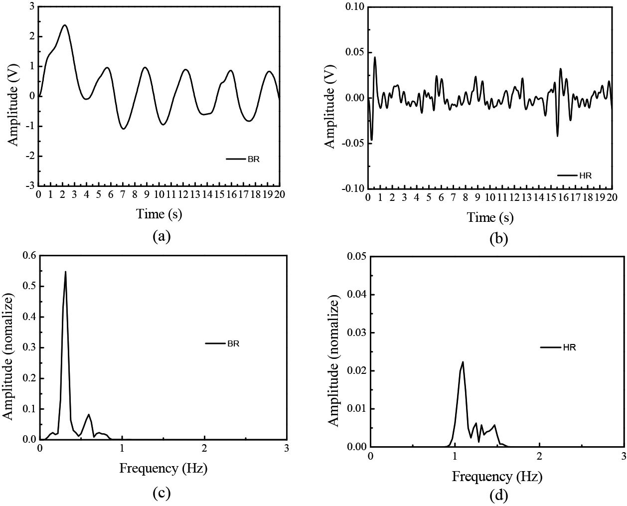
First, we give the experiments of Fig. 4 to show the correctness of the proposed radar system without using the digital filters. As can be seen in Fig. 4b, there is a maximum and a secondary peak value around the frequency of 0.3 Hz and 1.1 Hz, respectively. It can be found that the time-domain signal has the noise signal of high frequency in prior to operations of digital filter. In order to obtain the high signal quality, we use the two bandpass filters whose frequency response given in Fig. 3 to remove out-of-band noise. The filtered time-domain signal and the corresponding frequency response are provided in Fig. 5. Obviously, the out-of-band noise is completely reduced to a great extent. Figures 6 and 7 show the measured breathing and heat signals of original raw signal and the filtered signal, respectively, for case II. Figures 8 and 9 show the measured breathing and heat signals of original raw signal and the filtered signal, respectively, for case III. As expected, when the digital filter is applied to the original raw signal, the accuracy of breathing rate and heat rate could be further improved.
Measured breathing and heartbeat data (a) time domain and (b) frequency domain (Case III).
Measured breathing (left panel) and heartbeat data (right panel) with frequency and time domains, respectively (Case III).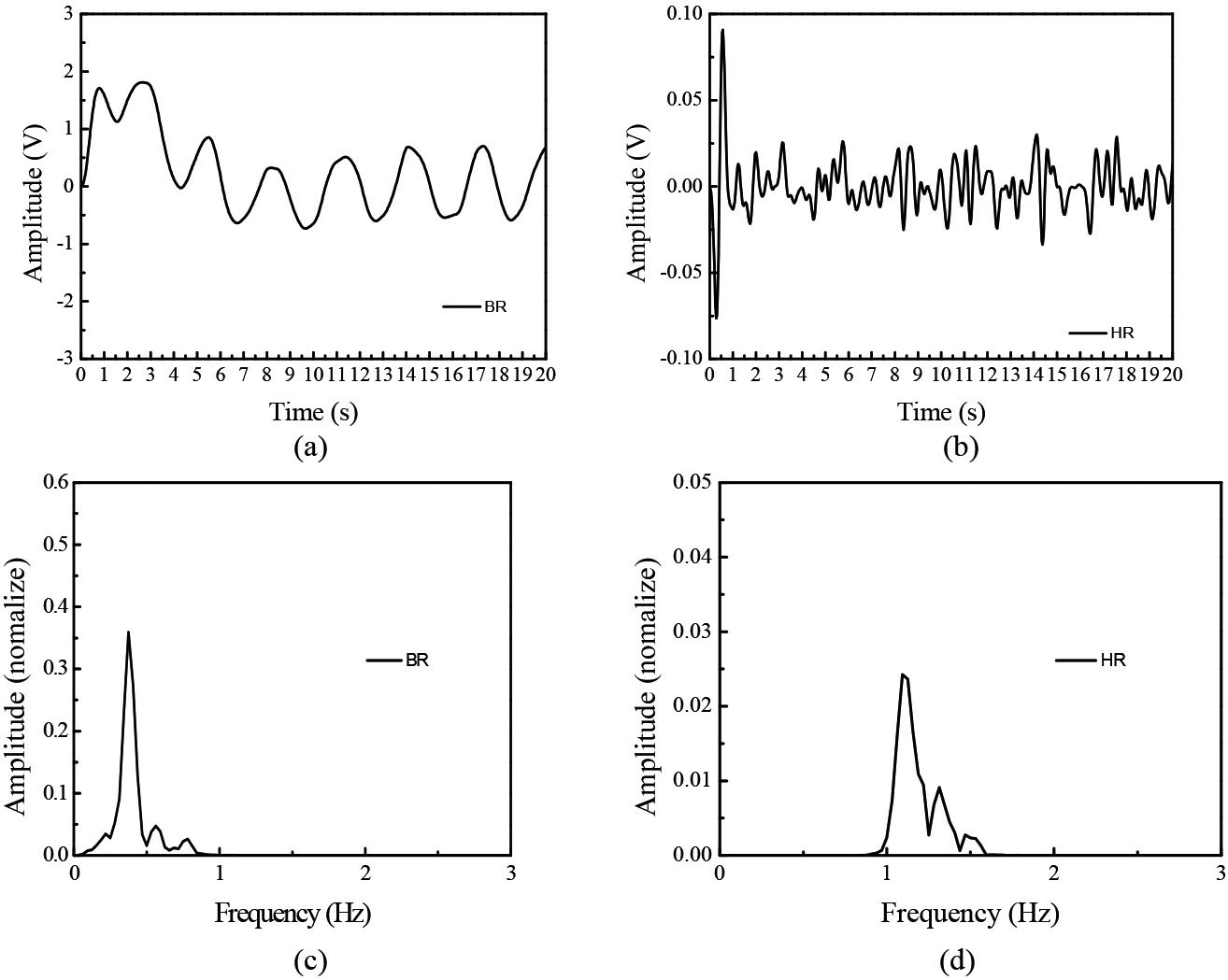
A fully customized UWB radar with function of through wall for vital-sign application is presented. The radar system plan with wall parameter is also incorporated into the design consideration to meet the FCC requirement and SNR. Notably, the data processing part adopts digital filtering techniques for observing physiological data clearly. To demonstrate its capability, the through-wall radar is analysis, design, and measured. The experimental collected data successfully exhibits great performance of breathing and heart rate behavior for real-time monitoring.
Footnotes
Acknowledgments
This work was partly supported by a grant from the Kaohsiung Armed Forces General Hospital and the Ministry of Science and Technology, Taiwan (MOST 109-2221-E-218-024-MY2).
Conflict of interest
None to report.