
Abstract
BACKGROUND:
Both professional and personal car drivers use smartphones as In-Vehicle Infotainment System (IVIS) and generally mount it wherever they feel convenient. Inappropriate or sub-optimal positioning of navigation devices increases off-road eye-glance duration and fixation frequency.
OBJECTIVE:
The current research aimed to develop a smartphone holding device to facilitate the mobile-phone’s easy mounting on the steering wheel’s hub, ensuring the screen’s visibility at a comfortable viewing angle in a vertical upright position irrespective of the steering wheel’s rotation.
METHODS:
A systematic product design methodology was adopted to develop the final product. The morphological chart was adopted for generating the different concepts of the smartphone mounting device. A Pugh chart was used for screening the various concepts generated in the previous step. Finally, a prototype of the selected best concept was made. User acceptance was assessed by taking feedback from users, and System Usability Scale (SUS) was used for usability evaluation.
RESULTS:
The developed innovative mounting device was light-weight and easy to use (SUS score 83.5). The final prototype was very effective in changing the angle of the smartphone to facilitate easy visibility at a comfortable viewing angle through the use of a ball and socket mechanism at the base. A ball bearing system was used in the mobile-phone holder for maintaining vertical stationary position during steering wheel rotation.
CONCLUSION:
As the device is useful for mounting the smartphone on the steering wheel’s hub, it might reduce driver distraction.
Introduction
Globally, road accidents are the 8th leading cause of injuries and fatalities. Yearly, about 1.35 million deaths are caused due to road traffic accidents [1]. Driver distraction is one of the causes of road accidents; one of the major reasons for driver distraction is the use of mobile-phones while driving. The use of mobile phones has increased in our day-to-day life. According to Ericsson’s mobility report of 2018, the total number of mobile subscriptions worldwide was around 7.9 billion in Q3 2018 [2]. Nowadays, smartphones are used by both professional as well as personal car drivers for traffic information, navigation, and other information while driving. There is increased usage of mobile phones while driving, leading to a phenomenon called driver distraction [3, 4]. It is often found that drivers place the smartphone inside the vehicle at different locations (on the dashboard/ windshield near the central console, near the bottom of the A-pillar) [5]. In many instances, the drivers use a phone holder for mounting the smartphone in aforesaid locations. These mobile-phone holders are available in different shapes, sizes, and operational characteristics. Due to the placing of the smartphone (being used as an in-vehicle navigation system) at various locations as per the driver’s convenience, the amount of off-road time and frequency of eye-glance required for accessing information from the phone are considerably different. De Lumen et al. mentioned that the driver’s distraction level is significantly affected by the navigation device’s position [6]. There is no extensive guideline for optimal placement of the navigation devices (smartphone) for reducing effort for visual information access. Available guidelines (ADDA, RA 10913) are superficial and discuss only about safe zone for positioning of mobile-phone/navigation system based on drivers’ horizontal line of sight, and it doesn’t specify the ideal location of navigation device [7]. Formulating guidelines and implementing policies by the law enforcement bodies is an incremental process and requires time as these guidelines are dependent on the outcome of the empirical evidence or research [8]. It has been reported in several studies that a decrease in the horizontal viewing angle of the on-board displays reduces the driver distraction, thereby improving the overall safety of drivers and other commuters. In a simulated driving study, Wittmann et al. reported an exponential decrease in drivers’ performance as a function of the distance between the line of sight and on-board display position [9]. In corroboration to this finding, Zheng et al. mentioned that in-vehicle display positions with small visual angles had shown significantly shorter glance time in comparison to displays with larger visual angles [10]. In a study by Doi et al., a smaller visual angle had also shown to give faster and accurate reactions when Camera Monitor System (CMS) replaced the side-view mirror [11]. Following the aforementioned literature review, it is presumed that as nearer is the navigation system’s position to the on-road straightforward line of sight, smaller is the visual angle, thereby reducing an off-road glance while driving.
Some mobile-phone holders facilitate positioning the mobile-phones near the straight forward line of sight, such as dashboard, behind the steering wheel, and hanging from the windshield. None of these positions are useful as they either obstruct the forward on-road view field or demand eye movement and neck flexion/extension or rotation for viewing the screen. Earlier research [12] indicates that positioning mobile-phone on the steering wheel’s hub could be considered most suitable since it ensures minimal horizontal eye/neck movement being straight in front of drivers’ normal line of sight. Moreover, mounting a mobile-phone on the steering wheel’s hub does not obscure the instrument cluster’s visibility through the steering wheel and the forward on-road field of view. It also reduces viewing angle in relation to the straightforward on-road line of sight. Although there are varieties of holders for mounting in-vehicle navigation devices, very few products could be mounted on the steering wheel’s hub. Hence, the current research aims to develop a device to facilitate the mobile-phone’s easy mounting (as a navigational device) on the steering wheel’s hub in a vertical stationary position irrespective of the steering wheel’s rotation to facilitate easy visibility of the screen at a comfortable viewing angle.
Method
For this study, the following steps were followed: Field survey: Initially, a semi-structured interview (consisting of both closed and open-ended questions) was conducted with the drivers who were using the mobile-phone holder in their car. Concept generation: Concepts sketches of the mobile-phone holder were generated based on customer needs. A ‘morphological’ chart was used for developing alternate concepts of the product. Concept selection/screening: Different concept alternatives of the mobile-phone holder were compared, evaluated, and screened by the design team, using the Pugh concept selection matrix. Prototype development and field trail: A prototype was developed. The CAD model was generated before physical prototyping.
Development process of the mobile-phone holder
According to Ulrich et al., a product development process is a set of activities employed to conceptualize, design, and commercialize a new product [13]. The process of designing and developing a new product (mobile phone holder in this case) consists of two broad phases, each of which further divides into three sub-activities. These two phases are ‘ideation’ (consists of customer need identification, concept generation, and concept selection) and ‘prototyping’ (which consists of detailed design, prototype testing, refinement, and final production). The generic product development process is shown in Fig. 1.
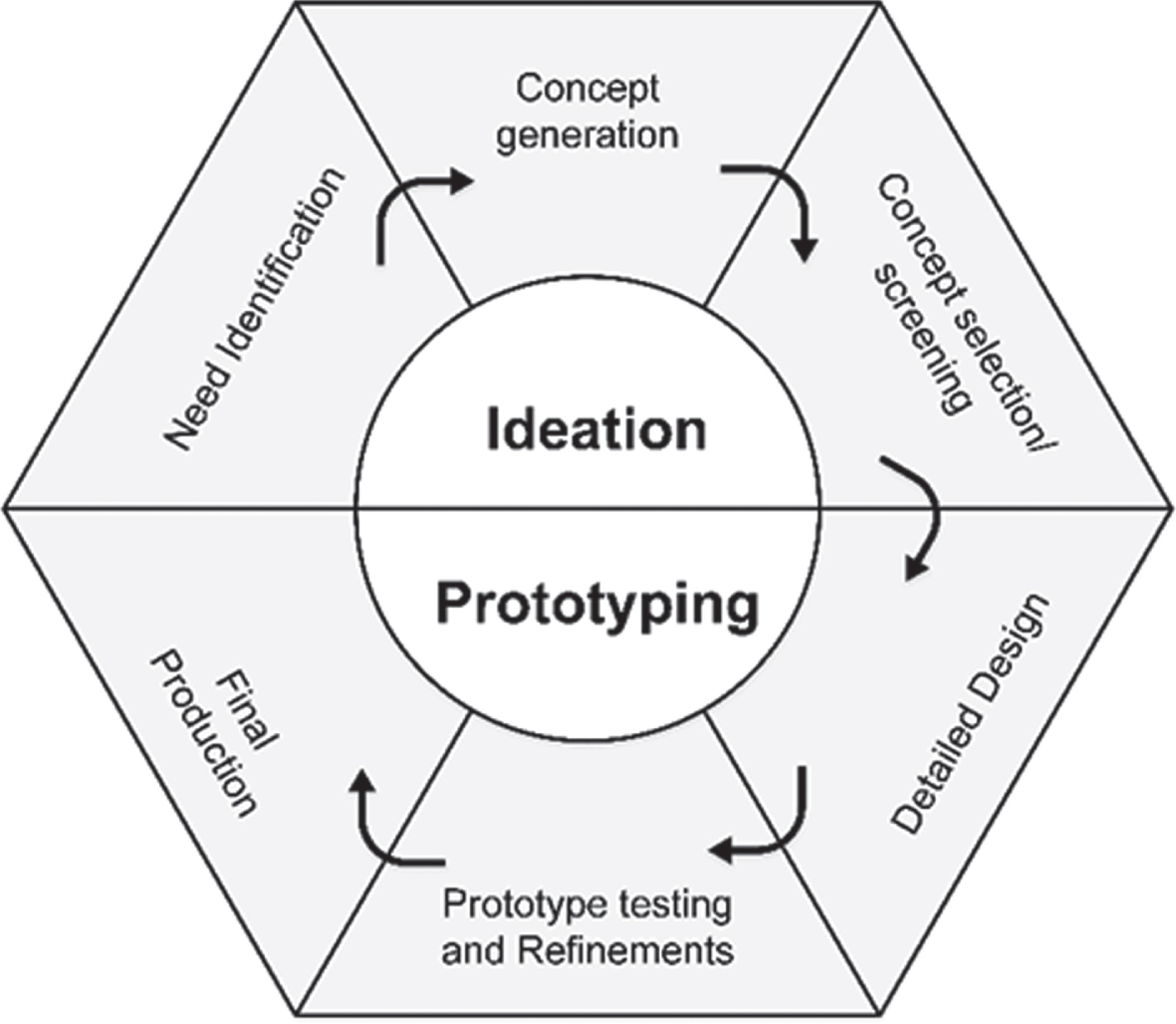
A generic product development process (Adapted from [12]).
Careful assessment of the market is needed for designing a successful new industrial product [14]. Ralph Keeney and Gary Lilien introduced multi-attribute analysis to demonstrate its potential in aiding the product design process [15]. A semi-structured interview was conducted to understand the customer needs. This survey involved drivers (age: 18–45 years) having a valid Indian driving license for a light moving vehicle (LMV), a minimum of one year of driving experience, and driving MABTS (Mobile Application Based Taxi Service) company vehicle. A purposive (non-probability) sampling technique was followed for selecting the participants. It was an anonymous survey, and the survey’s participation was entirely voluntary without any incentives. As MABTS drivers in India are predominantly male and female drivers are rare, 107 male drivers took part in this survey process.
The semi-structured interview covered the aspects of their mobile-phone holder’s usage pattern, relative placements around the steering wheel, cost, size, etc. Their response was noted, and the data were interpreted in terms of customer needs to formulate the design objectives. It helped in designing the concept of the product.
Concept generation
From the reported literature, it is understood that the mobile phones/navigational device should be placed nearer to or on the driver’s straight forward line of sight to minimize distraction caused by inappropriate positioning of the mobile-phone [12]. Moreover, mounting the mobile-phone on the steering wheel’s hub would be the most suitable position since it ensures minimal horizontal eye/neck movement and does not obscure forward on-road field of view. Hence, during the brainstorming session conducted with a small group of designers, it was decided to design a mobile-phone holder that could be mounted at the steering wheel’s hub. Thereafter, to generate various mobile-phone holder concepts, a matrix containing all the possible solutions called the morphological chart [16] was prepared (shown in Table 1). For the current study, the intended functionality of the product was divided into the following five sub-functions: 1) Fixing on the steering wheel, 2) Viewing angle adjustment, 3) Type of clamp opening, 4) Holding mechanism, 5) Rotating mechanism; and for each of the functions, five alternative options were made (shown in Table 1). Six (06) alternative concepts of the mobile-phone mounting device were prepared by using one option for each of the functions.
Morphological chart for the mobile-phone holder for car
Morphological chart for the mobile-phone holder for car
Concept selection is a critical stage in the product development process. After developing various concepts, the most appropriate concept was selected or screened out based on the design objectives described earlier. The design team evaluated the concept alternatives and gave scoring based on the design objectives. Different concepts of mobile phone holders were assessed using the Pugh chart [17, 18] for concept selection, and a decision matrix was prepared. The design team voted concept ‘2’, be chosen as ‘DATUM’ or reference, with which other selected concepts would be evaluated. The concept alternative, which received a higher score, was proceeded further with prototype development.
Creation of virtual mock-up in CAD
A virtual mock-up of the selected mobile-phone holder concept was prepared before making the prototype. A three-dimensional, solid CAD model was created using Solidworks (V16) software; various parts of the product were made and assembled using the Solidworks platform. Two-dimensional drawings of all the parts of the mobile-phone holder with measurements (in mm) were drafted.
Prototype development
Various components of the mobile-phone holder were gathered and suitably modified in the design studio as per the conceptualized mobile-phone holder’s requirement. The prototype consisted basically of three parts: (a) base, (b) ball and socket, (c) mobile-phone holder. The base was prepared using thermoform plastic as material by vacuum forming process. A miniature ball bearing (No. 698zz) was procured from the market. This ball bearing was used to prepare the mould of the base and was finally fixed inside the base, such that it does not skip out. The second part was the ball with a small stick made of nylon. It was prepared by turning process in the lathe. For preparing the third part of the mobile-phone holder, the holder mechanism, ‘Jugaad’ [19, 20] technique, was used. This part was taken from an already existing product in the market.
Usability testing and user feedback
User feedback was collected to check the efficacy of the developed product. Fifteen drivers volunteered to participate in the study. The demonstration was given about fixing the mobile-phone holder on the steering wheel’s hub, and it’s working during navigation and driving tasks. Table 2 shows the questionnaire for feedback. The novel mobile-phone holder’s usability was evaluated using the System Usability Scale (SUS) [21]. A fresh group of fifteen (15) male drivers (who did not participate in the previous survey) were selected for usability evaluation and gathering feedback regarding the developed prototype following the same inclusion criteria described in section 2.2. The developed prototype was given to the volunteers individually for their use and interactions. Their feedbacks were collected along with the rating on SUS. The SUS scores were interpreted in terms of adjective rating and acceptability [22, 23], as shown in Table 3.
Questions used during user feedback
Questions used during user feedback
SUS scores with corresponding adjective and acceptability rating
Insights from the field survey
From the volunteers’ response (n = 107), the data regarding the relative percentage of drivers and their cost preference of mobile-phone holders they use were extracted (as shown in Fig. 2).
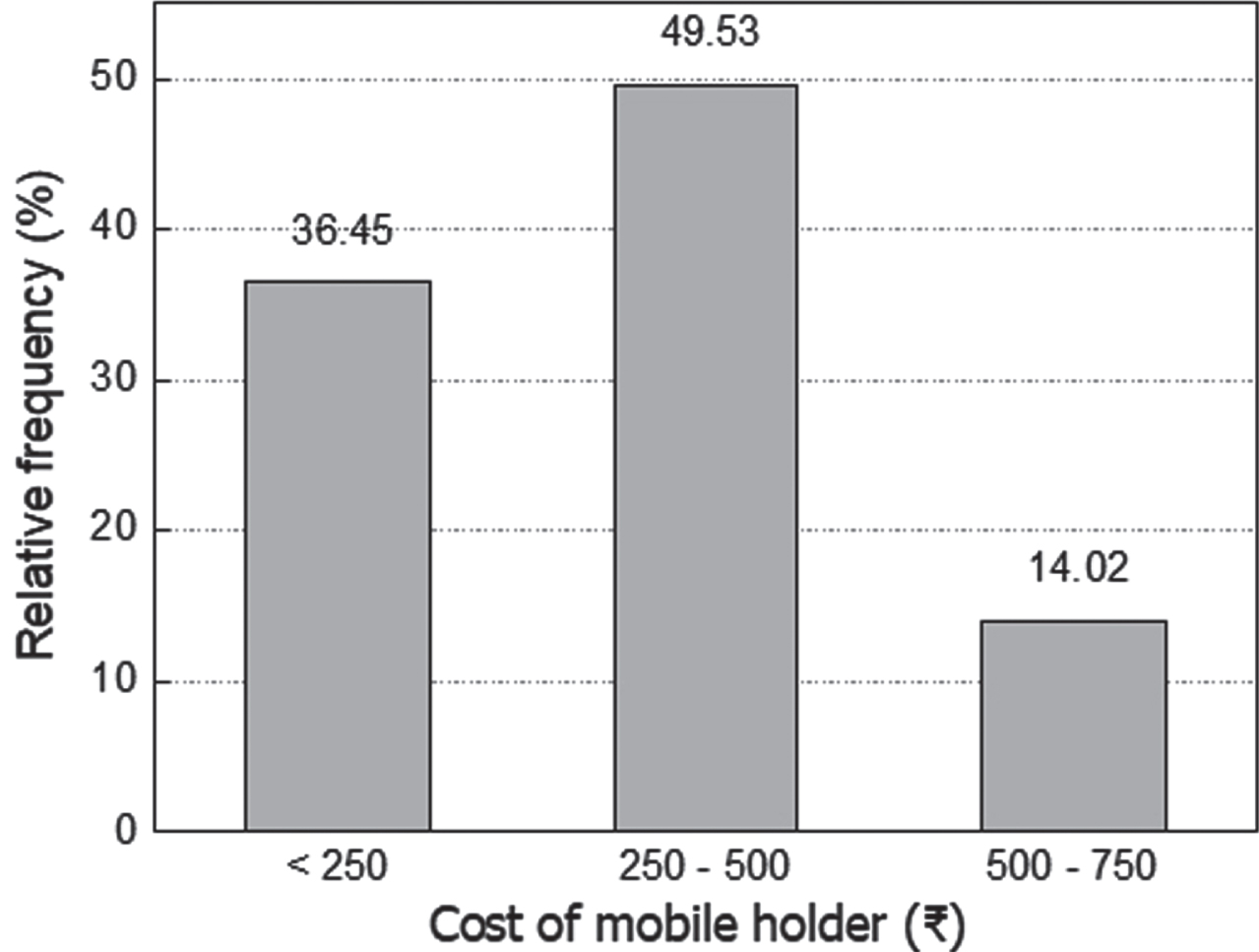
Relative percentage of the mobile-phone holder cost.
About 50% of the drivers used mobile-phone holders, ranging from  250–500 ($3.5–$7); whereas, 36.45% preferred to use mobile-phone holders below 250 ($3.5). For the question, what size of mobile-phone they use for navigation purposes in their cars, about 24.3% of drivers used mobile-phone having a screen size of 4.5 in. Some other mobile-phone screen sizes being used by the drivers recorded during the survey were 4.7 in (19.6%), 5 in (15%), 5.5 in (13.1%), 5.2 in, and 5.3 in (each 9.35%). Figure 3 shows the frequency curve of mobile phone size and their relative usage percentage by drivers during the survey.

Relative percentage of mobile phone size.
The drivers were also asked about their preferred position of keeping the mobile phones (left, right, or center). About 57.9 % preferred keeping their mobile phone on the left side, whereas 36.4 % said they like to keep it on the right side, a small percentage, and 5.6 % said they keep it at the center. It was also noted that everyone said that they would like to operate and install the mobile-phone holder with minimum effort and without any assistance. Hence, the following design objectives were formulated based on customer needs: Size: The mobile-holder easily mounts at the center of the steering wheel without hindering its free movement. Installation: It should be easy to install on the steering wheel. Adjustability: The mobile-holder should allow changing the angle of viewing the mobile-phone and keep the phone upright even while steering wheel movement. Universality: It should be able to adjust to accommodate mobile phones of different sizes. Cost: The mobile-phone holder is lower in cost than the existing competitors’ products.
A morphological chart was used for generating concepts. Table 1 shows the mobile-phone holder’s morphological chart for the car, with various options as a column and different functions as each row. Many concepts were generated (by choosing one option for each function of the product) using the morphological chart. The design team selected six concepts that were found to be feasible. Functional features of the novel product were decided according to the customers’ need, and thereby design objectives were set. Thus, each of the concepts was obtained from a combination of one option for each function; these combinations for each concept are given below in Fig. 4.

Different concepts of mobile-phone holder developed.
These concepts of the mobile-phone holder are shown in Fig. 4 (a–f). A brief description of each concept is given below: Concept 1: In this concept, the phone is held from the sides by the arms of the holder, which come out uniformly by the use of a rack and pinion mechanism. The phone can be tightly fixed by pressing the arms of the holder with the phone. A ball bearing is attached at the back, which in turn is attached to the steering wheel by a stick pad. Hence, the holder can rotate and stay in an upright position even when the steering wheel is rotated. This concept is shown in Fig. 4a. Concept 2: The sketch is shown in Fig. 4b. The phone can be held from top and bottom by a clipping mechanism. The back-side of this is attached to the bearing through the pivot of the clip. Hence, the angle of the phone can also be adjusted. The bearing can be attached to the steering wheel by a stick pad. Concept 3: In this concept, the phone is held from the bottom corners. The jaws open by a rack and pinion type mechanism. By pressing the jaws, we can tighten the mobile- phone. A bearing is attached at the back of the holder, which can be fixed at the steering wheel’s center by a stick pad. The bearing attachment position is not at the center of the holder but above the horizontal axis —shown in Fig. 4c. Concept 4: In this, the phone is held from the top and bottom. The mobile-phone fits in by extending the bottom jaw of the holder, which is spring-loaded. At the top, a screw can be tightened to fix the position of the mobile-phone. A bearing is attached at the back, which is again attached to the steering wheel stick pad —shown in Fig. 4d. Concept 5: This concept is shown in Fig. 4e. This holder consists of a three-jaw system - two sideways and one at the bottom. A ball bearing is attached at the back, which can be fixed to the steering wheel by a stick pad. The center of this holder is above the horizontal axis to maintain the phone weight to the bottom. Concept 6: In this concept (shown in Fig. 4f), the mobile phone is held by two jaws of the mobile holder, which opens simultaneously by the press of a button, by rack and pinion mechanism. The jaws can be closed by pressing them together. A rotating mechanism is provided with the help of a miniature bearing, which maintains the mobile holder in an upright position when the steering wheel is rotated. The center of this bearing is attached to the ball and socket joint, which allows the facility to change the mobile angle when it is attached to the mobile holder. The entire assembly can be easily fixed at the center of the steering wheel.
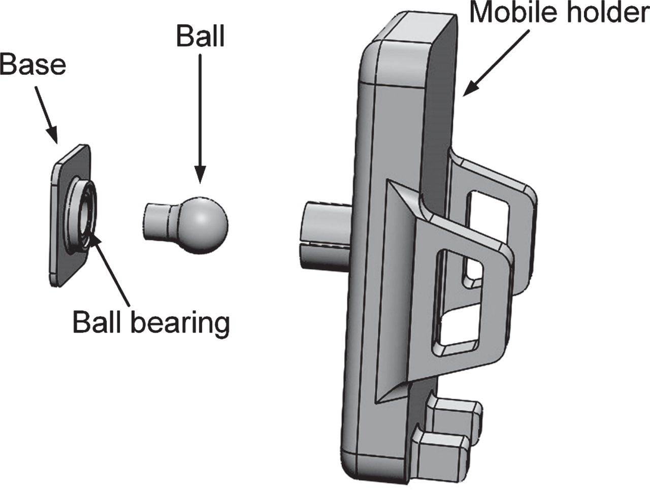
Exploded view of the mobile-phone holder.
Based on the Pugh chart matrix, the scores obtained for different concepts are shown in Table 4. Out of all the alternatives, concept ‘6’ received the highest score of ‘5’, and it was further taken-up for physical prototype development.
Pugh concept selection matrix for a mobile-phone holder for car
Pugh concept selection matrix for a mobile-phone holder for car
Three-dimensional solid CAD modeling of the different parts was made and then assembled in SOLIDWORKS (V16) platform. Figure 5 shows the mobile-phone holder’s exploded view; various views of the product are shown in Fig. 6. The 2-dimensional drafting (with measurements in mm) of the mobile-phone holder concept is shown in Fig. 11. The physical prototype of the conceptualized mobile-phone holder is depicted in Fig. 7. It consists of three parts: (a) Mobile-holder (b) ball and socket (c) base. The approximate cost of the developed prototype is between $4 to $5.
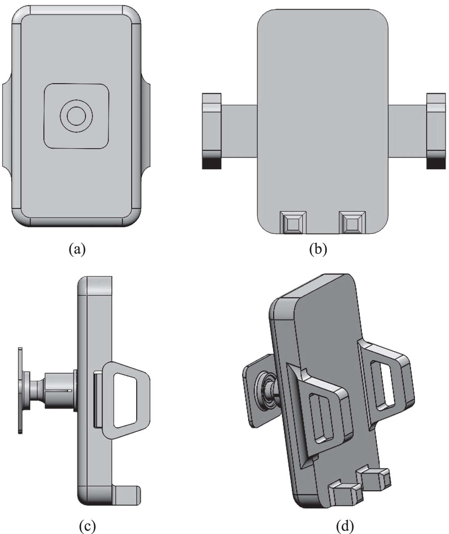
Different views of the CAD model of the mobile-phone holder, (a) back-view, (b) front-view, (c) side-view, (d) isometric view.
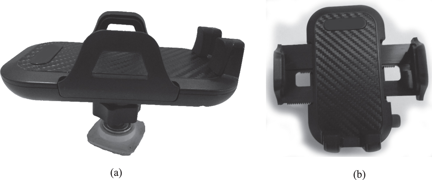
Different views of the prototype mobile holder, (a) side-view, (b) top-view.
A SUS score value of 83.67 was obtained, which shows a “good” and “acceptable” usability rating, according to the adjectives shown in Table 3. The ratings for various items of SUS are shown in Table 5. Figures 8 9 show the ratings for these odd and even-numbered questions, respectively, in a pictorial form. It was observed that the responses were mostly ‘agree’ and ‘strongly agree’ for odd-numbered questions (positively phrased); in-contrast to even-numbered questions (negatively phrased) where most of the responses varied between ‘disagree’ and ‘strongly disagree’.
System Usability Scale items and their ratings
System Usability Scale items and their ratings
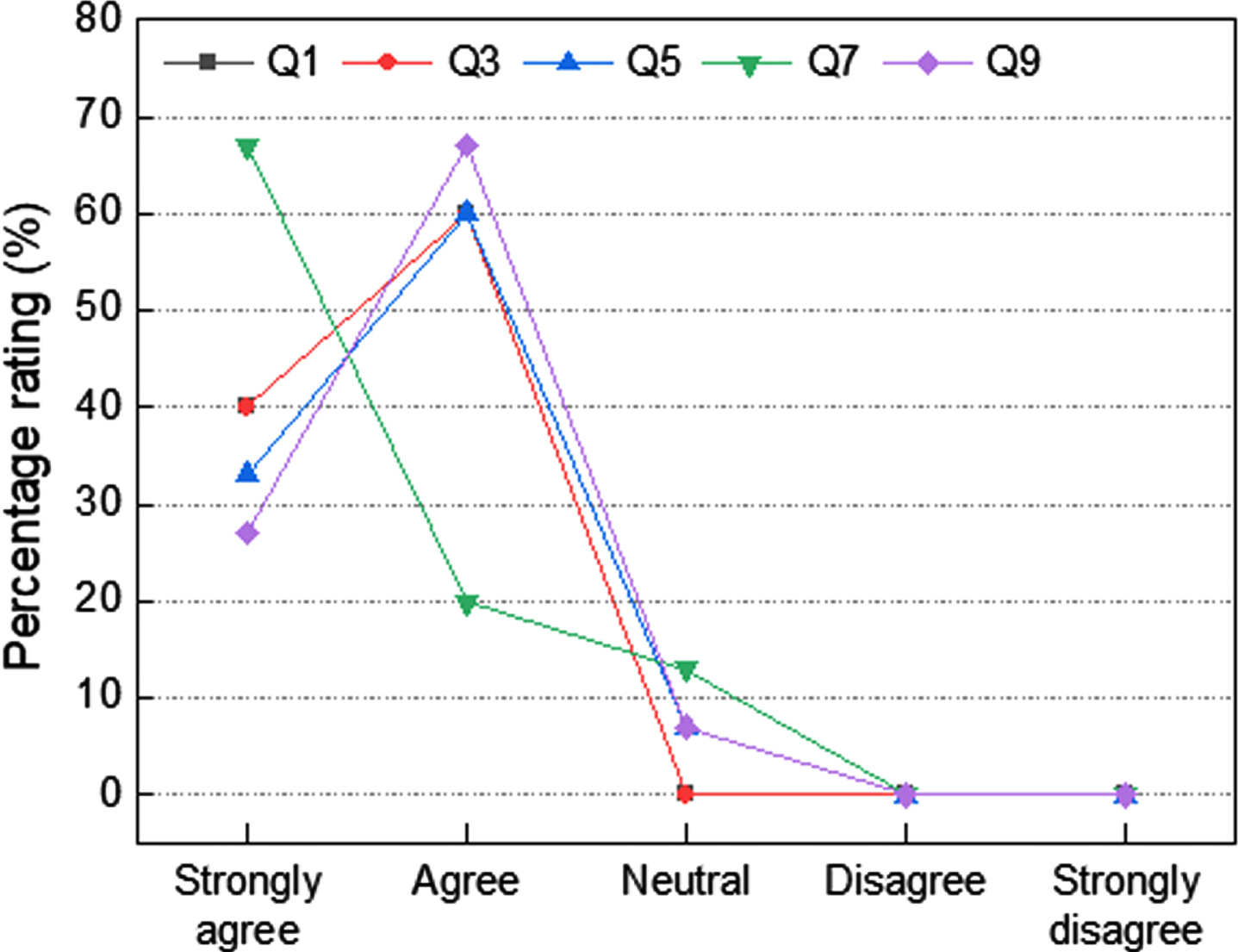
Percentage ratings for questions 1, 3, 5, 7, 9 of System Usability Scale.
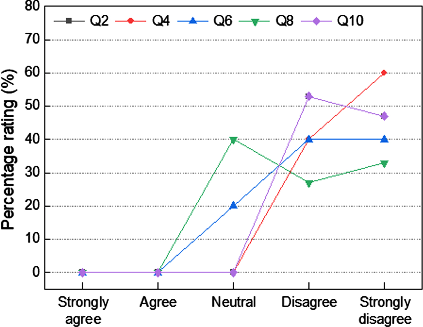
Percentage ratings for questions 2, 4, 6, 8, 10 of System Usability Scale.
The feedback of the users was recorded using the questionnaire (shown in Table 2). The mean ratings by the users are shown in Fig. 10. An overall feedback score of 4.46 out of 5 was obtained. A horizontal line at ‘3’ indicated the median value. The mean score for all the questions was above it. This indicated the overall positive feedback by the users. The smartphone mounting device was tested under the naturalistic driving condition. It was observed to move/rotate about 10–15 degrees under sudden jerks and motion (due to rotation of the steering wheel). It returned to its initial vertical position within 600 to 700 milliseconds after the sudden motion subsides. Dimensions of the individual components of the mobile-phone mounting device are shown in Fig. 11 to make the design comprehensible for the readers.

Graph showing mean feedback score for different questions.

Two-dimensional drafting of the CAD model (all measurements in mm).
The literature review unveils that placing visual displays nearer to the straight forward line of sight (which have smaller viewing angles) results in improved performance of drivers by reducing the glance time as well as reaction-time to visual display and consequently reduces driver distraction [9, 10]. Therefore, mounting the mobile-phone as an in-vehicle navigation device close to the straight forward line of sight must improve the driving performance. Positioning/mounting of the mobile-phone on the steering wheel’s hub was planned as it is presumed to be beneficial. It allows lesser viewing angle and unobscuration of the forward on-road view field as well as instrument cluster located behind the steering wheel. Following earlier reported research, it could be apparent that the hub of the steering wheel is the best-suited location for mounting mobile-phone for navigational purposes, but the superiority of the selected location should be empirically established. Objective methods of experimentation using eye-tracking [6], driving simulator [11], and neck angle (flexion, extension, and lateral movement) measurement should be utilized for this purpose.
Although there is negligible horizontal/lateral eye and/or neck movement to visualize the smartphone positioned on the steering wheel’s hub, there is still a requirement of downward eye and/or neck movement. Mobile-phone could be alternatively placed on the dashboard or hanging from the windshield to avoid downward eye and/or neck movement, but these positions lead to the forward view field’s obstruction. Another alternative to avoid downward eye and/or neck movement is the use of Head-Up Display (HUD), but there are various limitations of using HUD, as stated by earlier researchers [24]. Moreover, HUDs are costly, and it is not compatible for various navigation applications. The developed product (a device for mounting smartphone on steering wheel hub) is innovative due to novelty in its features compared to those already existing in the market. The novel features of the mounting device include (a) provision for fixing the phone/navigation device at the hub (center) of the steering wheel, (b) use of ball and socket joint which allows for adjustment of the angle of mobile-phone for better viewing experience (drivers can easily adjust the viewing angle of the mobile-phone for better visibility and to reduce the glare), (c) application of ball bearing system to the mounting device to enable the upright position of the mobile-phone despite steering wheel’s rotation, (d) light-weight (approx. 200 gm). Detailed product development methodology, starting from conceptualization to prototype development, has been demonstrated in the current research. The adopted method is in corroboration to other innovative product development techniques [13, 18].
Brainstorming session with the designers’ group was instrumental in generating optional ideas for each of the mounting device’s sub-functions. By using a morphological chart, a large number of concepts were possible in the given time. Additionally, the designers improved the product’s overall quality through a slight change in components by referring to the morphological chart to address the same function [25]. Similar scientific endeavors where morphological analysis was used include smart furniture design [26], education [27], automotive components [28], architecture [29], etc. The best solution among the generated concepts of the mounting device was determined using the Pugh matrix. This simple technique has been effectively used in comparing the alternative concepts in the diverse domains of product design, including electrical appliance [30], packaging/containers [31], etc. SUS, which has been used in current research for measuring the perceived usability, effective use of this tool is also found in evaluating the usability of the systems related to mobile-app development [32], healthcare device [33], automobile [34], and hand-tool design [35]. In the current research, SUS was adopted to check the mounting device’s usability as this tool was reported to be the most reliable option even with a small number of participants [36].
Limitations
Although the researchers have taken utmost care, a few limitations still exist in the present study. A notable limitation of the study is the considerations of the opinion and feedback only from male drivers. India’s MABTS driver population predominantly consists of males; thus, collecting the female drivers’ responses was not feasible due to their unavailability. Since females are different from males in anthropometric and biomechanical (total and comfort range of motion) characteristics, the inclusion of female drivers in future studies might give a different perspective on automobile accessories (product) design. Inclusion of both male and female drivers would lead to designing a product that is suitable irrespective of gender difference. Secondly, the final prototype was made using ‘Jugaad’ technique, which might be deficient in craftsmanship and not ideal for mass production. Further studies could fruitfully explore product forms, assembling mechanisms, different materials, and manufacturing technology for mass production and make the product much affordable. The business plan to commercialize the developed mounting device is beyond the current study’s scope and can be taken up in the future. Additionally, as the product is innovative and has market potential, protecting Intellectual Property Rights (IPR) is also needed.
Conclusion
Following the current research, an innovative smartphone mounting device was developed through a systematic user-centered product design approach. The developed product is in-expensive, light-weight, easy to use, and has the potential to be a marketable product. It is expected that the positioning of a smartphone at the steering wheel’s hub with the help of the developed mounting device would reduce the biomechanical effort of the neck and/ or eye movement for information access from the screen along with unobscured visibility of road and instrument cluster. All these favorable impacts would be beneficial in the reduction of driver distraction.
Footnotes
Acknowledgment
The authors acknowledge the help received from Mr. Akshay Mohankar and Mr. Ayush Kr. Das in 3D CAD modeling of the final concept.
Conflict of interest
None to report.