
Abstract
BACKGROUND:
It is often unrealistic to assume that the subject remains stationary during a computed tomography (CT) imaging scan. A patient rigid motion can be decomposed into a translation and a rotation around an origin. How to minimize the motion impact on image quality is important.
OBJECTIVE:
To eliminate artifacts caused by patient rigid motion during a CT scan, this study investigated a new method based on frequency domain analysis to estimate and compensate motion impact.
METHODS:
Motion parameters was first determined by the magnitude correlation of projections in frequency domain. Then, the estimated parameters were applied to compensate for the motion effects in the reconstruction process. Finally, this method was extended to helical CT.
RESULTS:
In fan-beam CT experiments, the simulation results showed that the proposed method was more accurate and faster on the performance of motion estimation than using Helgason-Ludwig consistency condition method (HLCC). Furthermore, the reconstructed images on both simulated and human head experiments indicated that the proposed method yielded superior results in artifact reduction.
CONCLUSIONS:
The proposed method is a new tool for patient motion compensation, with a potential for practical application. It is not only applicable to motion correction in fan-beam CT imaging, but also to helical CT.
Introduction
The artifact reduction is one of the most important problems in CT reconstruction. Many different factors may lead to increased artifacts, such as the limitations of CT equipment and reconstruction algorithm and the motion of the patients. And one of the major sources of image artifact in CT is patient motion, which is the most difficult to correct [1–4]. Wagner et al. reported all the patients were subject to head motion during CT even though they were instructed not to do so before scanning. The averages of the mean translation excursion (MTE) and the mean rotation excursion (MRE) were found to be 2.5 mm and 1.06°, respectively [5]. Unfortunately, these are only average values and the motion range is much greater in some cases. If a moving object is reconstructed without motion correction, eminent streaks or even “double images” could be produced [6–8]. Due to the relatively high radiation dose associated with CT scanning that can provide injury to humans, it is undesirable to repeat the scan if motion occurs. Hence it is very important to develop algorithms and techniques to compensate motion artifacts in CT [9–12].
Rigid motion can be divided into translational motion and rotational motion, which are coexistent. However, correction method is different according to different types of motion [13–15]. Several approaches for motion artifact reduction in CT scan have been investigated. Generally speaking, they can be classified into three categories. The first is to minimize motion effects, Li and his colleagues improved temporal resolution by increasing rotation speed of the gantry. This technique is restricted by the scanner’s mechanical limits, and has the disadvantage of reducing the image signal-to-noise (SNR) ratio [16, 17]. Multi-acquisition or overlapping half-scan methods were also carried out by discarding motion corrupted image datasets and reconstructing an image from the remaining non-motion corrupted projections [18–21]. This method is not effective for constant motion, and increases patient dose. The second is to correct the motion using external motion monitoring devices. Their main drawback is that they require additional hardware [22–24]. The third is to estimate the motion parameters and compensate for the motion effect in the image reconstruction [25–27]. The method was proposed in [28] to estimate the motion parameters only from sinogram based on the Helgason-Ludwig consistency condition method (HLCC). However, this method needs a lot of computation due to dependence on a searching algorithm, and has a disadvantage of poor estimation accuracy when the motion curve is complex. The authors of [29] proposed a method to estimate and correct the motion in CBCT, but only for CBCT. Sun et al. [30] proposed a method to iteratively estimate and compensate the motion during the reconstruction. But the iterative processing requires long computation. The third category has still great research potential.
In this paper, the proposed method is in the third category to estimate the motion parameters based on frequency domain analysis. First, the relationships are derived between the rigid motion parameters and projections in fan-beam. The rigid motion can be estimated by the magnitude correlation of projections in frequency domain. It realizes the estimation of rotation and translation simultaneously. Then, the estimated parameters can be introduced into an improved fan-beam filtered back-projection reconstruction algorithm to correct motion artifacts. Finally, this method can be extended to helical CT. The experimental results demonstrate the efficacy of the proposed method.
Materials and methods
Motion estimation in fan-beam
Fan-Beam projection with general in-plane motion
Let us denote a bounded object function in the x-y plane by f (x, y), which is defined on a compact support

Fan-beam geometry and variables.
According to the geometric relationship defined in Fig. 1, we have
Assuming γ is a small value, we can make use of the replacement of same value infinitesimal to simplify procedure and solve the problem easily. Hence, Equations (1) and (2) can be simplified as
Finally, we obtain the projections for a rigid object in the fan-beam geometry
According to the Fourier shift property, for any projection view angle
When the X-ray source rotates a circle, each projection can be detected twice by detector
Thus, for each projection view angle β1 ∈ [0, π - 2γmax), γmax is the maximum angle of γ, there must be a projection view angle β2 ∈ [π, 2π - 2γmax) which satisfies the equation
To ensure the existence of the conjugate projection series for a rigid object, we have the view angle
Assuming the X-ray source rotates at a constant velocity ω = 2πrad/ - s along a circle, and there are n fan-beam projection view angles β (β ∈ [0, 2π)) and p fan-beam projections
For any x
λ
, we can find a y
λ
corresponding to
Thus, we can achieve the rigid motion view-by-view. If we assume that φ
z
(t), d
x
(t) and d
y
(t) are smooth and continuous, we can approximate φ
z
(t), d
x
(t) and d
y
(t) with finite basis functions φ0 (t) , φ1 (t) , …, φ
N
(t), namely
Without loss of generality, we select φ
N
1
(t) = t
N
1
and φ
N
2
(t) = t
N
2
. Considering the initial time t = 0, there will be φ
z
(0) = 0, d
x
(0) = 0 and d
y
(0) = 0. Hence, Equation (12) can be simplified as
There are N1 + 2N2 unknowns that are p1i, p2j and p3j, and m independent equations in Equation (14). For actual applications, m is much larger than N1 + 2N2. Therefore, we can determine the unknown variables as follows
Equations (15–18) are the main results of the proposed motion estimation method.
Once both the rotational and translational parameters are estimated, image reconstruction can be performed to compensate for the motion effects. We can introduce the estimated parameters into fan-beam filtered back-projection reconstruction algorithm to correct motion artifacts. According to the Fourier shift property we compensate for the motion
Finally, we obtain the corrected image by fan-beam filtered back-projection reconstruction algorithm. The flow of motion compensation is shown in Fig. 2.

Motion artifact reduction flow.
Let us consider a single-slice helical CT projections can be denoted by g (β, γ, z), where β denotes the angular position of the source, γ denotes the angle between the projection line and the center line of the fan-beam, and z denotes the longitudinal position of the slice being projected [32]. We assume the projections for a rigid object (d
x
, d
y
, d
z
, φ
x
, φ
y
, φ
z
), namely
According to the Fourier shift property, we take a 2D FFT with respect to
In the continuous case, the fan-beam redundancy is described by the relationship
Thus, for each projection view angle β1 ∈ [0, π - 2γmax), γmax is the maximum angle of γ, there must be a projection view angle β2 ∈ [π, 2π - 2γmax) which satisfies the equation F2 [g F (β1, γ, z)] = F2 [g F (β2 + 2γ, - γ, z)] equality. Considering an object with a rigid, we have
where t1 and t2 represent the corresponding scanning times for
Therefore, the rigid motion (d x , d y , d z , φ x , φ y , φ z ) can be estimated slice-by-slice by magnitude correlation and phase correlation of projection data in frequency domain [33–36]. Finally, according to the Fourier shift property we compensate for the motion slice-by-slice, and the corrected image can be obtained by fan-beam filtered back-projection reconstruction algorithm [25, 32].
To demonstrate the feasibility of the proposed method, we performed simulation on a modified Shepp-Logan head phantom [37] and human head CT images as shown in Fig. 3. The additional tiny circles in the modified Shepp-Logan head phantom are used to simulate the small tissue as shown in Fig. 3(a).

Head phantoms for simulation. (a) is the modified Shepp-Logan head phantom; (b) and (c) Image1 and Image2 are the human head CT images.
In experiments we used fan-beam sinogram. The phantom was placed inside a disk of radius 128 mm, and the initial scanning time was t = 0. The X-ray source was rotated at a constant angular speed ω = 2πrad/ - s along a circle of radius R = 500 mm. There were 720 projection view angles and 1000 detector cells distributed along the collinear detector array. The size of detector aperture was 0.3 mm and γmax = 0.174rad/ - s. Poisson noise was added to the projection data such that 106 photons were emitted from the X-ray source towards each detector cell [28]. The basis functions were set to φ N (t) = t N and N1 = N2 = 3 in our preliminary study.
The mean translation excursion (MTE) and mean rotation excursion (MRE) are used to evaluate the motion range of an object. Additionally, we use the compensative mean translation excursion (CMTE), relative mean translation excursion (RMTE), compensative mean rotation excursion (CMRE) and relative mean rotation excursion (RMRE) to evaluate the accuracy of motion estimation [28].
First, we conducted simulation experiments using the modified Shepp-Logan phantom. The motion patterns in three typical cases are listed in Table 1. Group I simulated the ideal motionless case, Groups II and III simulated the complex motion patterns that are cosine and exponential form. The tests were conducted in 30 groups to evaluate the performance of our proposed motion estimation method. In Table 2, the motion was estimated based on the two motion models: the translational motion model (TMM) that ignores the rotation and the general motion model (GMM) in this paper. In Group I, both the GMM and TMM do not introduce deviation. In Groups II and III, the GMM is superior to the TMM since the rotation has been compensated. Therefore, the rotation cannot be ignored.
Motion patterns
Motion patterns
Motion estimation results of the TMM and GMM
Table 3 shows the comparison of results between the proposed method based on the GMM and the HLCC method in [28]. In Group I, the proposed method does not introduce deviation. In Groups II and III, the proposed method is superior to the HLCC method. The rotation estimation accuracy of the proposed method seems slightly higher than the HLCC method, while the translation estimation accuracy of the proposed method is higher than the HLCC method by about 50%. Comparing the running times of the three groups, we find that the proposed method is much lower than the HLCC method.
Motion estimation results and running times of Shepp-Logan phantoms
The estimated results for Group III are plotted in Fig. 4 to demonstrate the advantage of our proposed motion estimation method. The motion curves for the left, middle and right columns correspond to φ z (t), d x (t) and d y (t). Clearly, the estimated motion curves of the proposed method are closer to the real motion than the HLCC method. The results indicate that the proposed method has a better performance on motion estimation accuracy and real-time.
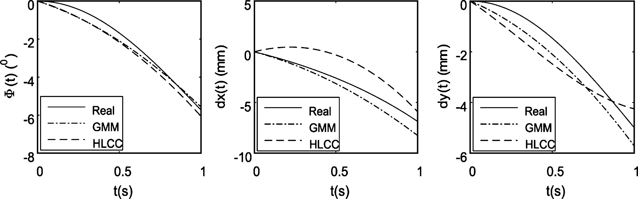
Real motion and estimated motion results for Group III.
All the reconstructed images are shown in Fig. 5. The motion parameters for the three rows correspond to Groups I to III in Table 1. First column images were reconstructed from sinogram with rigid motion and noise by the traditional FBP algorithm with no motion compensation. Second and third column images were reconstructed from sinogram with rigid motion and noise by the improved FBP algorithm with the GMM-based compensation and the HLCC-based compensation. Clearly, both two methods have a good performance on artifact reduction in Group I. In Groups II and III, the proposed method is superior to the HLCC method in image quality of circle regions where tiny structures existed since the motion estimation accuracy of the proposed method is higher than the HLCC method.
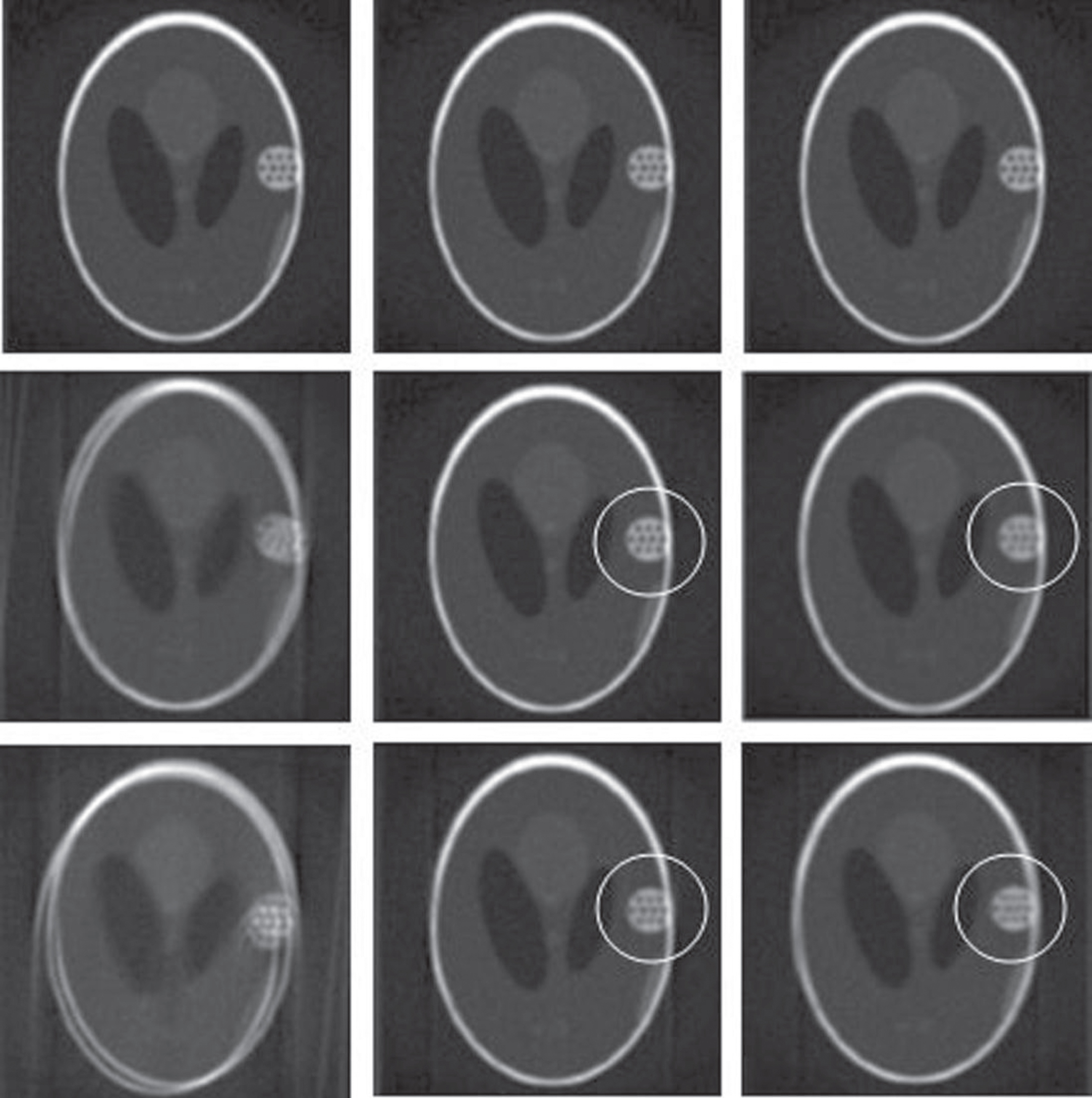
Motion artifact reduction in Shepp-Logan phantom for Groups I to III. First column images are reconstructed by the traditional FBP algorithm with no motion compensation. Second and third columns are reconstructed by the improved FBP algorithm with the GMM-based compensation and the HLCC-based compensation. The motion parameters for the three rows correspond to Groups I to III.
To further illustrate the performance of the proposed method, we use the root mean square error (RMSE), Pearson correlation coefficient (CC) and mean structural similarity index (MSSIM) to judge disparity between the reconstructed images and the ideal phantom [24, 38]. Table 4 shows the comparison of artifact reduction effect for Group III.
Comparison of artifact reduction performance on Shepp-Logan phantom for Group III
In Table 4, we can see that each RMSE of two methods is less than uncorrected, and the RMSE of the proposed method is the smallest and reduce about 41% than the HLCC method. Each CC and MSSIM of two methods is closer to 1 than uncorrected, and the CC and MSSIM of the proposed method are the greatest and increase about 28% and 49% respectively than the HLCC method. The results indicate that the proposed method has a better performance on motion artifact reduction.
The following simulation experiments were taken using the human head as shown in Figs. 3(b) and 3(c) to verify the artifact reduction effect of the human body. The head CT images were acquired from a GE Hi-Speed multi-slice CT scanner. 720 views were uniformly selected over a 360° range under 150 mA X-ray tube current and 120 kVp. All of the reconstructed images are 512×512 pixels. The real head motion obtained by Kim et al. [24] and estimated motion results are plotted in Fig. 6. Figure 6(a) shows the estimated results of a head case as in Fig. 3(b), and Fig. 6(b) shows the estimated results of a second head case as in Fig. 3(c).
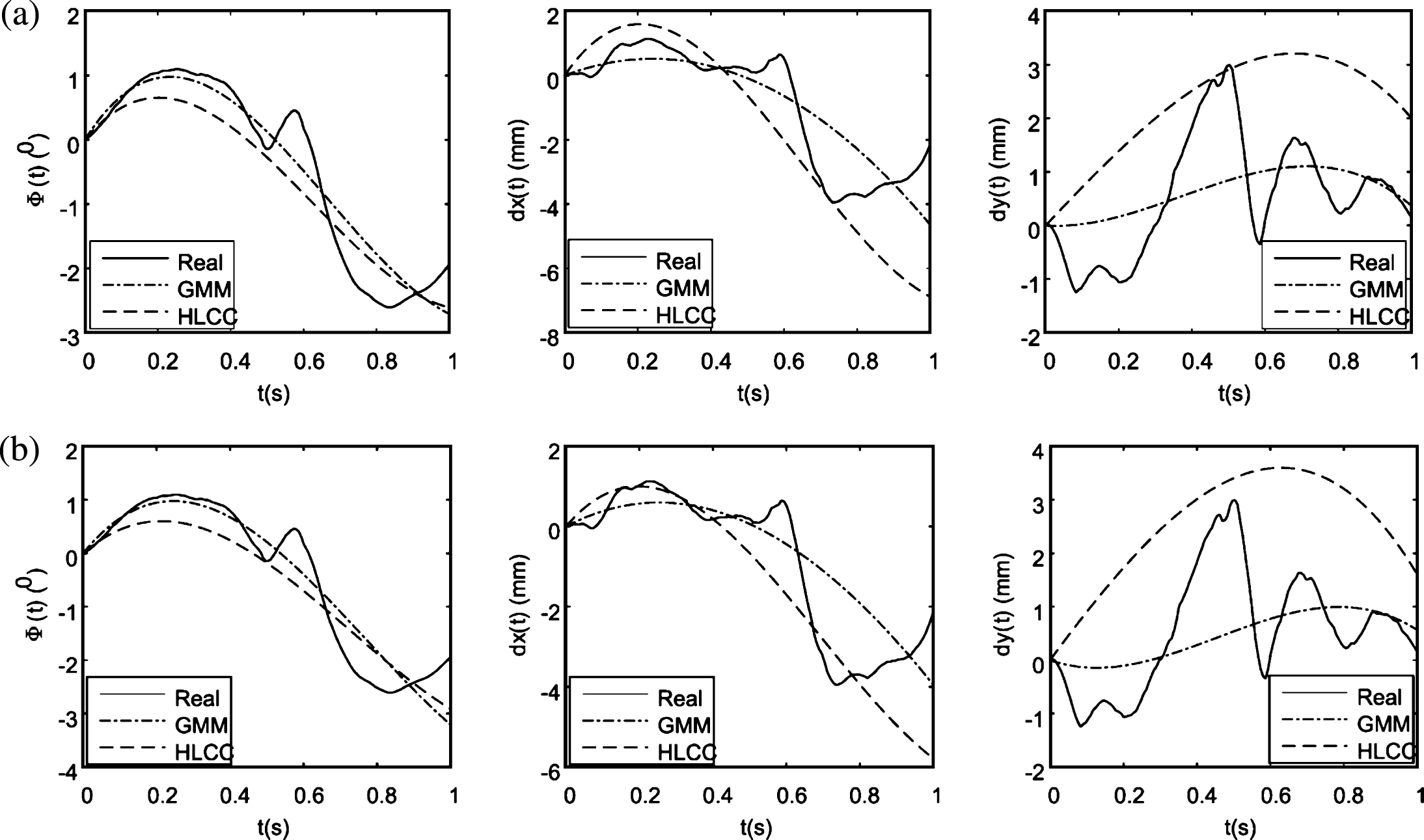
Real head motion and estimated results. (a) are the results of the proposed method and HLCC method for Image1; (b) are the results of the proposed method and HLCC method for Image2.
To quantitatively evaluate the accuracy of the real head motion estimation results between the proposed method and the HLCC method, we use the RMRE and RMTE to quantify the results, as shown in Table 5. We can observe that the RMRE and RMTE of the proposed method are much lower than the HLCC method. So the proposed method has better motion estimation accuracy for real human experiments.
Real head motion estimation results of human head images
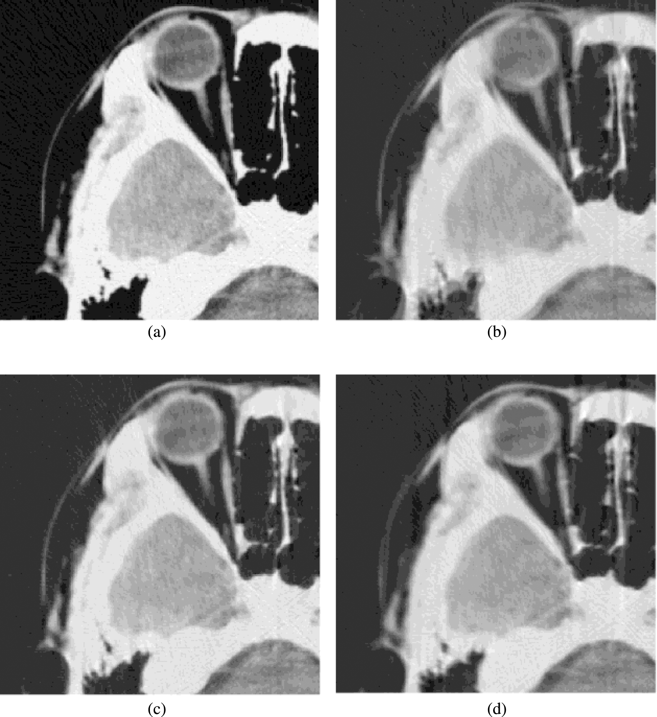
All the reconstructed images are shown in Figs. 7 and 8. To view the texture of reconstructed images more clearly, the zoomed images of a region of interest (ROI) from the corresponding images of Figs. 7 and 8 are shown in Figs. 9 and 10. We can see that the motion-corrected images obtained by our proposed method are very close to the stationary simulation phantom. Some streaks are observed near bony structures in Figs. 9(d) and 10(d).

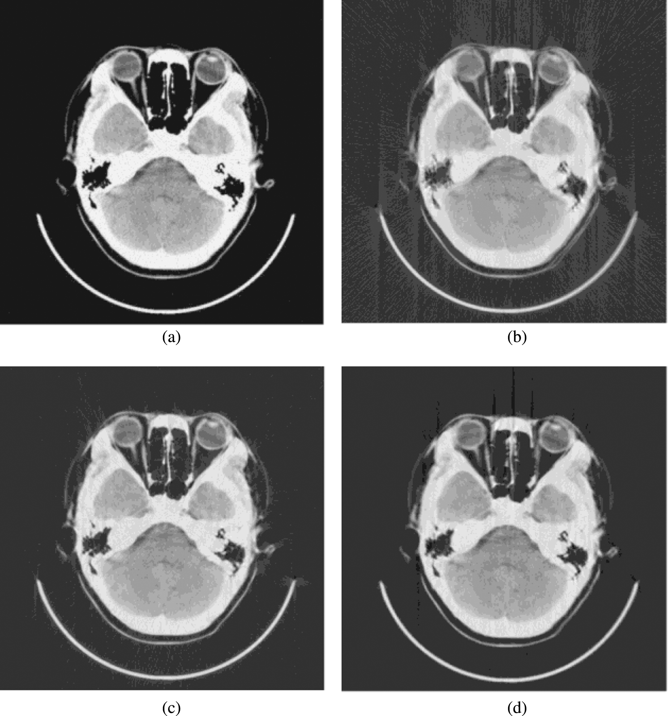
Motion artifact reduction in Image1. (a) is stationary simulation phantom; (b) is reconstructed by the traditional FBP algorithm with no motion compensation; (c) and (d) are reconstructed by the improved FBP algorithm with motion compensation based on our proposed method and the HLCC method.
Motion artifact reduction in Image2. (a) is stationary simulation phantom; (b) is reconstructed by the traditional FBP algorithm with no motion compensation; (c) and (d) are reconstructed by the improved FBP algorithm with motion compensation based on our proposed method and the HLCC method.

Zoomed images of a ROI from Fig. 7.
Zoomed images of a ROI from Fig. 8.
To quantitatively evaluate the proposed method, we compared respectively the reconstructed images in Figs. 7 and 8 by the RMSE, CC and MSSIM as shown in Tables 6 and 7. The RMSE of the proposed method is the smallest and reduce about 39% than the HLCC method; the CC and MSSIM of the proposed method are the greatest and increase about 23% and 40% than the HLCC method. Therefore, the proposed method has a better performance on motion artifact reduction for real human experiments.
Comparison of artifact reduction performance on human head for Image1
Comparison of artifact reduction performance on human head for Image2
In this study, a rigid motion estimation and compensation method based on frequency domain analysis has been proposed in fan-beam geometry. The proposed method can determine the motion parameters by the magnitude correlation of projection data in frequency domain and compensate this motion in the reconstruction. In fan-beam CT, the experiments results on both simulated phantom and human head images have demonstrated that the proposed method is better than the HLCC method in estimation accuracy, real-time and artifact correction effect. Therefore, this method could be applicable to helical CT. The future development of our work includes further testing and validation on helical CT. Another development will concern the affine motion especially the dilatation will be estimated and compensated.
Footnotes
Acknowledgments
This work was supported by Natural Science Foundation of China (No.61340034), China Postdoctoral Science Foundation (No.2013M530873), Tianjin Research Program of Application Foundation and Advanced Technology (No.13JCYBJC15600), Natural Science Foundation of Tianjin of China (No.16JCYBJC28800) and International Excellent Postdoctor Training Program of Tianjin of China.