
Abstract
When testing small size and high density objects with a broad field-of-view (FOV) industrial CT system, multiple objects are always assembled evenly onto the turntable for detecting to improve test efficiency. However, the maximum X-ray’s penetrating path through the materials increases, which means the CT system should collocate with a high energy X-ray source and wide-dynamic range detectors to complete the CT scanning. In this study, we proposed and tested a novel and efficient CT scanning method based on linear-arrangement and synchronous-rotating multi-turntables without enhancing the energy of X-ray source and wide-dynamic range of detectors for the CT system. With this modality, multiple objects are assembled onto multiple synchronous-rotating turntables respectively, and X-rays within the FOV merely penetrate one single object when scanning. The corresponding filtered back projection algorithm for image reconstruction is deduced. The computer simulation and experimental results verified the feasibility of this novel method and the scanning time was reduced to 5–8 minutes when completing the scanning of 3 to 5 group objects.
Introduction
X-ray computed tomography (CT) has wide-range applications in clinical noninvasive diagnosis and industrial nondestructive testing. For industrial CT applications, test efficiency is always the focus in practice and research. In fact, the test efficiency should be placed on the top-priority in some circumstances, for instance, when a large amount of objects need to be tested rapidly.
Obviously, many factors limit the CT test efficiency, such as exposure time, the number of projections and performance of data processing [1]. Several methods have been proposed to improve CT test efficiency. High speed rotation is a direct way to reduce exposure time [2]. A lot of state-of-art reconstruction algorithms inspired by Compressive Sensing and Prior Information, which significantly improved the quality of CT image from a limited-views projection [3–9], explore the potential of low-dose and quick CT scanning. Also the GPU-based optimization approaches make real-timereconstruction with low-cost hardware available [10, 11]. Most of the above efforts specify in improving the hardware of CT system and performance of image reconstruction algorithms. Generally speaking, they are effective for one-object scanning. But for multi-objects-test purpose, with normal scanning mode, it’s not easy to find a trade-off between test efficiency, system cost and image quality, which means a novel scanning mode should be taken into consideration.
When developing an industrial CT system, we need to satisfy the needs of testing a large amount of small and high density parts with high efficiency. The normal wisdom is that multiple objects are assembled evenly onto one big CT turntable, as shown in Fig. 1(a). Then we can obtain the reconstructed images within one CT scan. Apparently, the X-rays within the field-of-view (FOV) penetrate more than one object during CT scanning, which means the CT system should collocate with a high energy X-ray source and wide-dynamic-range detectors. In this paper, we present a novel method to solve the problem. Within the FOV, each object is assembled onto one small turntable, all turntables are linear-arrangement and located evenly on a fixed platform, as shown in Fig. 1(b). All turntables will rotate synchronously during CT scanning. Then with one CT scan, multiple CT images of the tested objects can be reconstructed. Compared with Fig. 1(a), the X-rays Fig. 1(b) only penetrate one object during CT scanning. This novel design will highly decrease the cost without decreasing the CT efficiency and image quality, cause no need for high energy X-ray source and wide-dynamic-range detectors.
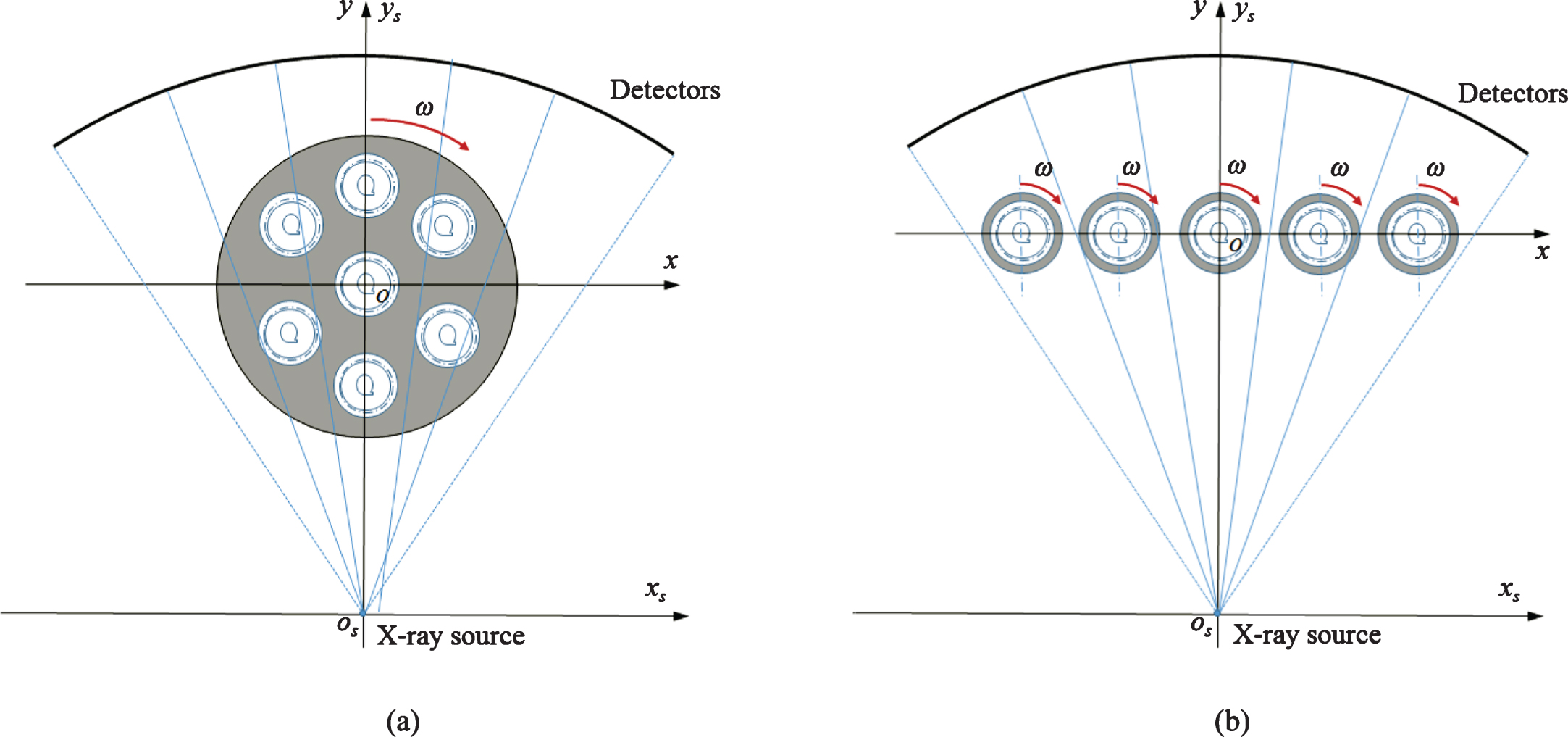
CT scanning sketches of multiple objects testing. (a) Multiple objects are assembled evenly onto a turntable.(b) Multiple objects are placed onto multiple synchronous-rotating turntables respectively.
The outline of this paper is organized as follows. In Section 2, the system geometry and the filtered back projection (FBP) image reconstruction algorithm are presented. In Section 3, numerical simulation and real-data experiments are described to demonstrate the feasibility of this novel mode. At last, we address several relevant issues and conclude in Section 4.
CT scan can be divided into 1st-5th generation on the basis of the scanning mode. In terms of test speed and system cost, the 3rd generation CT scan (i.e. the scanning locus is circular) is the mainstream scanning mode in industrial and medical applications. The novel efficient industrial CT scanning mode based on synchronous-rotating multi-turntables can be seen as the geometrical combination of multiple 3rd generation CT. Besides, the detector structure includes equiangular type and equidistance type. Except geometrical structure parameters, there are no substantial differences in scanning and image reconstruction algorithm between the two detector types, so the proposed geometry model with equiangular-type detectors can also be applied to the equidistance-type detectors.
Imaging model
In this section, we introduce the geometry of our proposed CT scanning mode. As shown in Fig. 2, the detectors are placed on a circular, N is the number of detectors, λ represents the angle size between adjacent detector-cells. S o is the distance from X-ray source to the detectors. There are n turntables linearly arranged within the FOV. The line passing through all the rotating centers of multi-turntables is perpendicular to the central X-ray of the fan-beam. R represents the distance from the line of the rotating centers to X-ray source. Thus, the global coordinate fixed on the rotating centers of multi-turntables can be written as σ : = o ; x, y}, where o is original point. The moving coordinate can be defined as σ s : = o s ; x s , y s } whose origin o s is fixed at X-ray source. For simplicity, we can further define σ i : = o i ; x i , y i } as local coordinate of the ith turntable, whose origin o i is fixed at the center of ith turntable. X I is the distance from o i to o, γ i is the angle between oo s and o i o s . Let ω denotes the turntables rotated angle related to the original position.
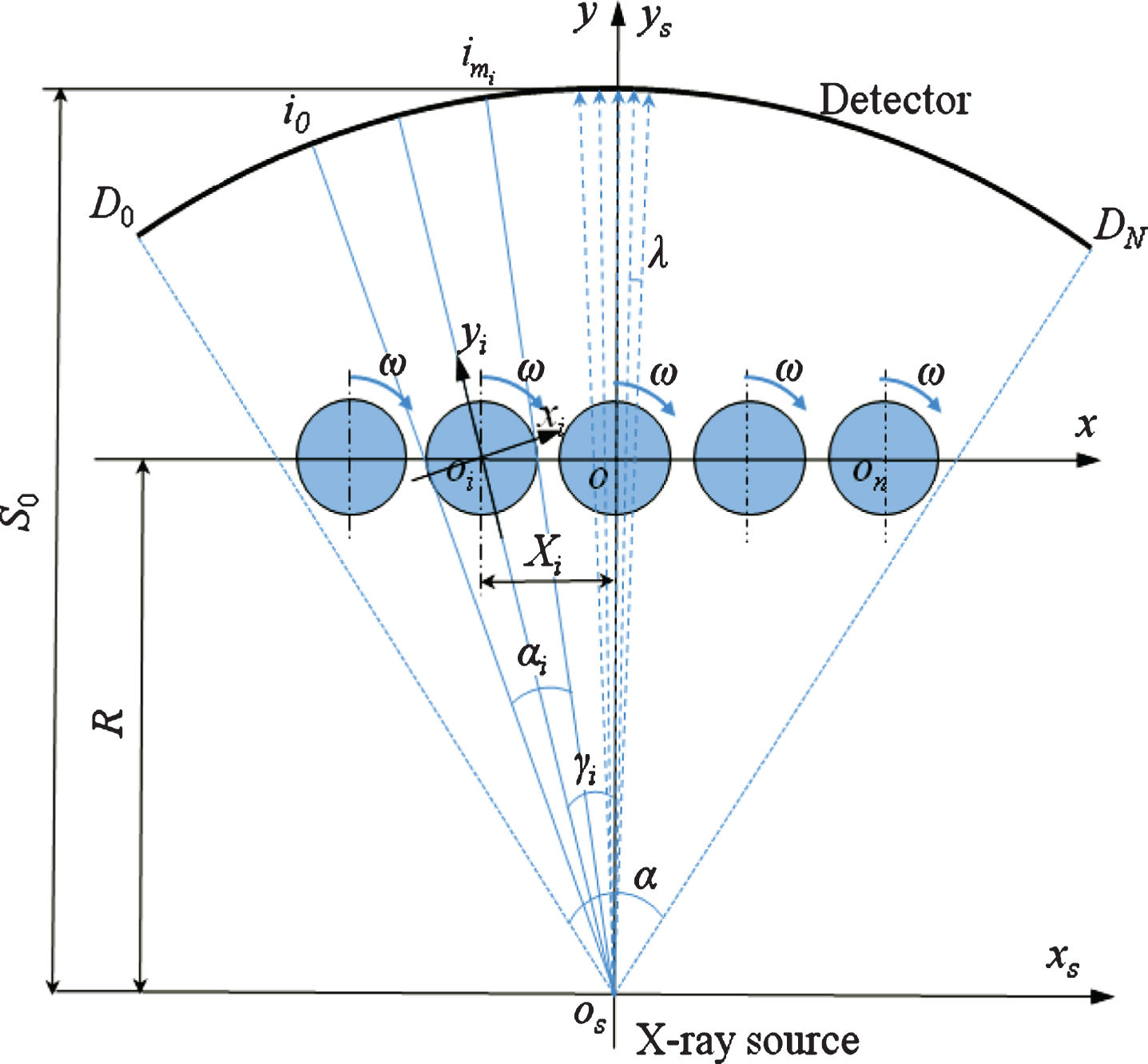
CT geometry of the novel CT scanning mode based on synchronously rotating multi-turntables.
The geometry model of the ith turntable is shown in Fig. 3. The radius of the ith turntable is r i . α i denotes the angle of fan-beam. R i is the distance between the source and the center of the ith turntable, i o → i m is the detector array corresponding to the FOV of the ith turntable. Therefore, the scanning mode of the ith turntable can be expressed as

CT geometry of the ith turntable.
As shown in Fig. 4, we assume the object is a compact support function f (x i , y i ) within the radius r i . is defined as the rotation coordinate relatively to the original position. Therefore, the projections p (s, θ) from the object f (x i , y i ) can be written as

Scan geometry of the ith turntable in the full FOV.
θ is the angle between the ray and the rotation coordinate, s is the distance from the origin to a specified X ray.
The parallel beam reconstruction is defined as [12]:
where is the ramp filter. Obviously, the view of each turntable is independent of one another, which means we only need the projection data over the range of [- r
i
, r
i
] for the ith turntable. Accordingly, f (x
i
, y
i
) is also written as
Equation (8) is the parallel-beam FBP reconstruction formula for the ith turntable. Now, let g (γ, ω) denote the fan-beam projection, γ is the angle between a fixed ray and the center ray of fan-beam, ω represents the rotated angle related to the original position of all turntables. Thus, we can get the expression of θ and s:
Furthermore:
where γ ∈ [γ
i
- a
i
/2, γ
i
+ a
i
/2] depends on the FOV of ith turntable. J = R
i
· cos(γ - γ
i
) represents the Jacobi factor. For simplicity, Equation (10) equals to
where,
According to the characteristic of filter function h (·), we can get
From the above analysis, we only discuss the ith turntable in specified coordinate. To realize the global coordinates, we should change the local coordinate σ i : = o i ; x i , y i } to global coordinate σ : = o ; x, y} under the relation that
From the above, Equation (11) can be simplified to
We have performed quantitative studies to evaluate and validate the proposed FBP algorithm in this section by computer-simulation and real data experiments.
Numerical simulation
As shown in Fig. 5, five testing phantoms with different sizes are fixed on five turntables from left to right respectively. The size of each phantom is shown in Table 1. Other scanning parameters are shown in Table 2. The pixel size of the reconstructed image is 0 . 5 × 0 . 5mm2. We took 720 views for data acquisition.
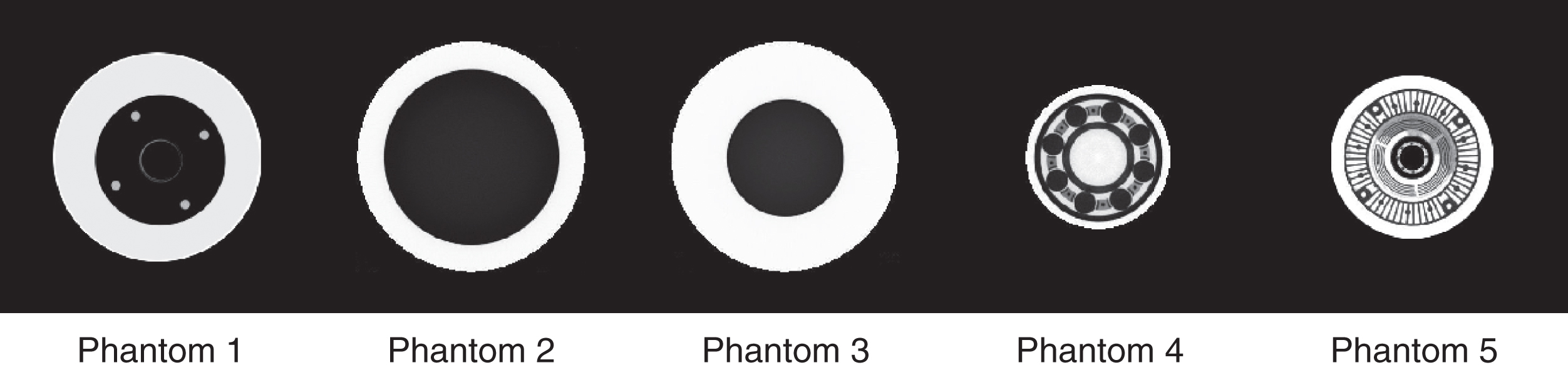
Original phantoms for numerical simulation.
Size of five different phantoms
Parameters for the numerical simulation
In the process of scanning, each tested object rotates synchronously around the center of its corresponding turntable, respectively. Figure. 6 shows the sinogram of projections. We can observe that the original tested objects are covered by the range of X-rays, and that the projections of each detected phantom do not overlap each other (i.e., the projections from specified object are confined to designated range).
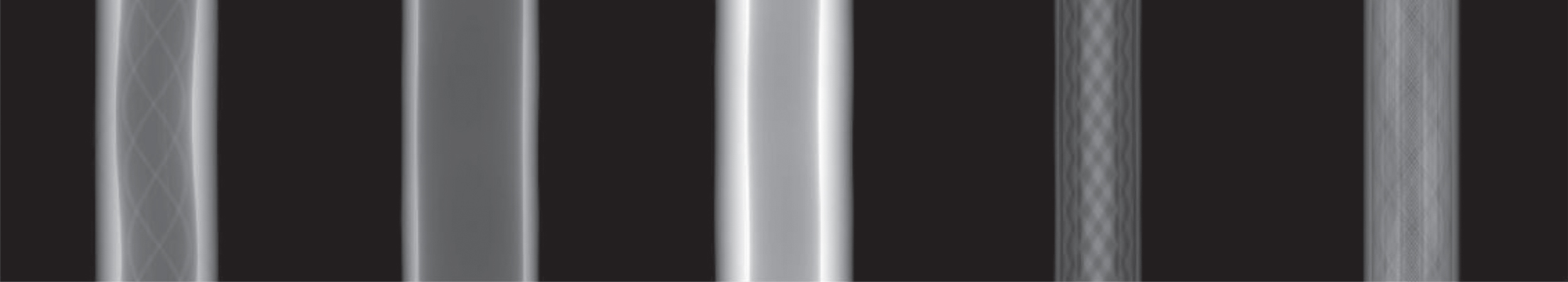
Sinogram of projections.
The reconstructed images by our proposed FBP algorithm are displayed in Fig. 7, and the root mean square error (RMSE) of each phantom is displayed in Table 3. From the results, we know that the novel CT scanning method is feasible and the proposed FBP algorithm can be applied.
The reconstructed images. The display window is [0 1].
RMSEs of reconstruction images
As shown in Fig. 8, we have constructed a real CT system with our proposed scanning mode and FBP reconstruction algorithm. This system consists of a 4 MeV X-ray source and CdWO4 detectors with 486 channels. In addition, 9 synchronous-rotating turntables with 200 mm diameter and 210 mm intervals are arranged linearly on top of a turntable with 600 mm diameter that can be used for conventional CT scan. While it is performed with conventional CT scan, the radius of FOV is 300 mm. R o is the distance from source to the center of the turntable. As it is performed on the novel CT scanning mode, the distance between the source and the central line of turntables is R, which is adjustable form 1100 to 1755 mm. As show in Fig. 9, with different R, only 2 to 3 turntables are within the fan beam. Correspondingly, 9 turntables are divided into 3 to 5 groups to be tested, which means the time for objects loading is decreased to improve test efficiency. The experiment scanning parameters are listed in Table 4.
The illustration of experimental CT setup. 9 synchronous rotating turntables with 200 mm diameter and 210 mm intervals are arranged linearly on top of a turntable with 600 mm diameter.
Scan geometry of the experiment CT system.
Parameters for experiments
From the parameters for experimental parameters we can see that completing the scanning of 3 to 5 groups objects just need 5–8 minutes, while the system just need activate once because multiply objects are loaded on turntables simultaneously. Compared with the mode of testing objects successively, which needs approximately 30 minutes in general, the test efficiency has been improvedsignificantly.
Two sets of multi-object CT slice images are displayed in Fig. 10. The images with sharp edges are free of artifacts. In fact, the system has been applied to test large quantity small complex metal parts. The test efficiency and image quality can meet the requirements.
Two sets of multi-object CT slice images. (a) displays the CT image with 2 tested metal parts and (b) displays the CT image with 3 different specimen.
From the real-data experiment in Section 3.2, it is seen that the system based on the proposed scanning mode cannot get all reconstructed images in a single CT scan because of the small-FOVs source. But there are no needs for high-Voltage X-ray source, high-dynamic-range detector and long exposure time, it provides a good trade-off between test efficiency, system cost, stability and image quality. Moreover, with the application of lager-FOVs source in future, the proposed mode can further improve test efficiency.
The proposed CT scanning methodology with linear-arrangement and synchronous-rotating multi-turntables can be seen as the geometrical combination of multiple 3rd generation CT. In section II, we have illustrated the geometrical relationships between the fan-beam and the turntables. In fact, it isdifficult to acquire the exact positions of the rotation centers because of the complex structure of industrial CT system [13]. Position errors of the turntables would inevitably result in the image edge blurring and reduce the system spatial resolution. On the basis of measuring the turning center methods [14, 15] and calibrating geometrical variation[16, 17] in single turntable model, how to automatically complete geometry calibration for the multiple turntables is one of the challenges for our subsequent efforts.
Synchronous-rotating turntables were designed linearly for simplicity and practicability. In fact, to obtain different magnification ratio and detection resolution for practical use, the layout of the turntables could be designed in non-linear or non-even. But there is a basic principle that the FOVs of turntables should not be overlapped. If the principle is not satisfied, a part of the projections would contain the attenuation information of more than one tested object. As a result, image reconstruction would be complex to complete and increase time-consuming in this case [18].
In conclusion, we have proposed a novel methodology for multiple objects CT scanning, and demonstrated its feasibility with fan-beam geometry. Specifically, the tested objects are placed onto linear-arrangement and synchronous-rotating multi-turntables respectively and the turntables rotate synchronously during CT scanning. Multiple CT images can be reconstructed with one CT scan to improve the test efficiency. Compared with the conventional CT scan, the system cost could be cut down by not collocating with enhanced X-ray source and detectors. Further study of the turntable positioning error compensation and image reconstruction algorithm for a complex set of turntables is under way. Also, this multiple objects CT scanning work will be extended to cone-beam geometry in the future.
Footnotes
Acknowledgments
The author would like to thank Dr. Luzhen Deng (CQU, China) for her valuable suggestions. This work was partially supported by the National Natural Science Foundation of China (No.61471070), China National Instrumentation Program (No. 2013YQ030629) and the Strategic Industry Key Generic Technology Innovation Project of Chongqing (No. cstc2015zdcy-ztzxX0002).