



Abstract
BACKGROUND:
Some patients cannot be imaged with cone-beam CT for image-guided radiation therapy because their size, pose, or fixation devices cause collisions with the machine.
OBJECTIVE:
To investigate imaging trajectories that avoid such collisions by using virtual isocenter and variable magnification during acquisition while yielding comparable image quality.
METHODS:
The machine components most likely to collide are the gantry and kV detector. A virtual isocenter trajectory continuously moves the patient during gantry rotation to maintain an increased separation between the two. With dynamic magnification, the kV detector is dynamically moved to increase clearance for an angular range around the potential collision point while acquiring sufficient data to maintain the field-of-view. Both strategies were used independently and jointly with the resultant image quality evaluated against the standard circular acquisition.
RESULTS:
Collision avoiding trajectories show comparable contrast and resolution to standard techniques. For an anthropomorphic phantom, the RMSE is <7×10- 4, multi-scale structural similarity index is >0.97, and visual image fidelity is >0.96 for all trajectories when compared to a standard circular scan.
CONCLUSIONS:
The proposed trajectories avoid machine-patient collisions while providing comparable image quality to the current standard thereby enabling CBCT imaging for patients that could not otherwise be scanned.
Introduction
Since the addition of an integrated kV-imaging, cone-beam computed tomography (CBCT) system to the clinical linear accelerator (LINAC) [14, 27] this modality has become one of the most popular forms of image-guided radiation therapy (IGRT). The tomographic information provided in the kV energy range improves soft-tissue contrast resolution over that provided by the MV electronic portal imaging device (EPID) alone [15] enabling it to guide patient setup and provide target verification in addition to monitoring tumor response during treatment [3, 36].
It is therefore detrimental to treatment when adequate tomographic information cannot be obtained from the kV-imaging CBCT system. One situation in which this can occur is when a collision between the patient and the machine arises. While substantial work has focused on the detection and avoidance of collisions in treatment delivery [2, 33], most studies do not consider the CT imaging which can pose additional challenges as it introduces another collision point, with the kV detector panel, and requires a full rotation for data acquisition. Collisions are a particular concern when imaging breast and lung cancer patients where the arm position above the head can often cause clearance issues with the patient’s elbow. A mock up of this situation is demonstrated with a mannequin in Fig. 1. Collisions also present problems in the treatment of posterior and lateral lesions in stereotactic body radiosurgery (SBRT) where clearance between the patient and gantry is reduced. Similarly in prone breast treatments, where the target is near the couch top and a large lateral couch translation is needed to bring the target to isocenter, collision with the contralateral side of the patient may occur. When collisions would occur, the angular range available for scanning is restricted and it is not possible to acquire a complete circular scan in the treatment position. The goal of this study is to provide increased clearance distances enabling imaging when collisions cannot be avoided during standard imaging trajectories while maintaining comparable image quality to standard trajectories.

Two examples of potential collision for a typical patient setup using a mannequin in a supine treatment position. As can be seen, collisions with the left elbow of the mannequin can occur both with the face of the MV treatment head (a) and with the kV detector (b) at the nominal position, 50 cm from isocenter.
Collision Avoidance Strategies and Theory
During a CBCT scan, as the gantry rotates, there are two components of the linac that are the primary sources of patient collision concerns. These are the MV-treatment head and the kV imaging detector, both situations shown in Fig. 1. Because the treatment head of the gantry is fixed, the patient must be moved away by translating the couch to avoid collisions by increasing clearance distances. By synchronizing this couch motion away from the linac head with the gantry rotation, a fixed distance (“virtual SAD”) between the MV source and a chosen center of rotation (“virtual isocenter”) in the patient can be maintained. At the beginning of the scan the patient is moved away from the linac head along the MV beam direction. As the gantry rotates, the couch moves continuously to maintain the specified separation as shown in Fig. 2. The virtual SAD can be chosen large enough so that collisions like the one shown in Fig. 1a are avoided. Note that it is only the distance to the linac head that is increased in the virtual SAD technique; the distance from the kV source and detector to the patient and to each other are unchanged.
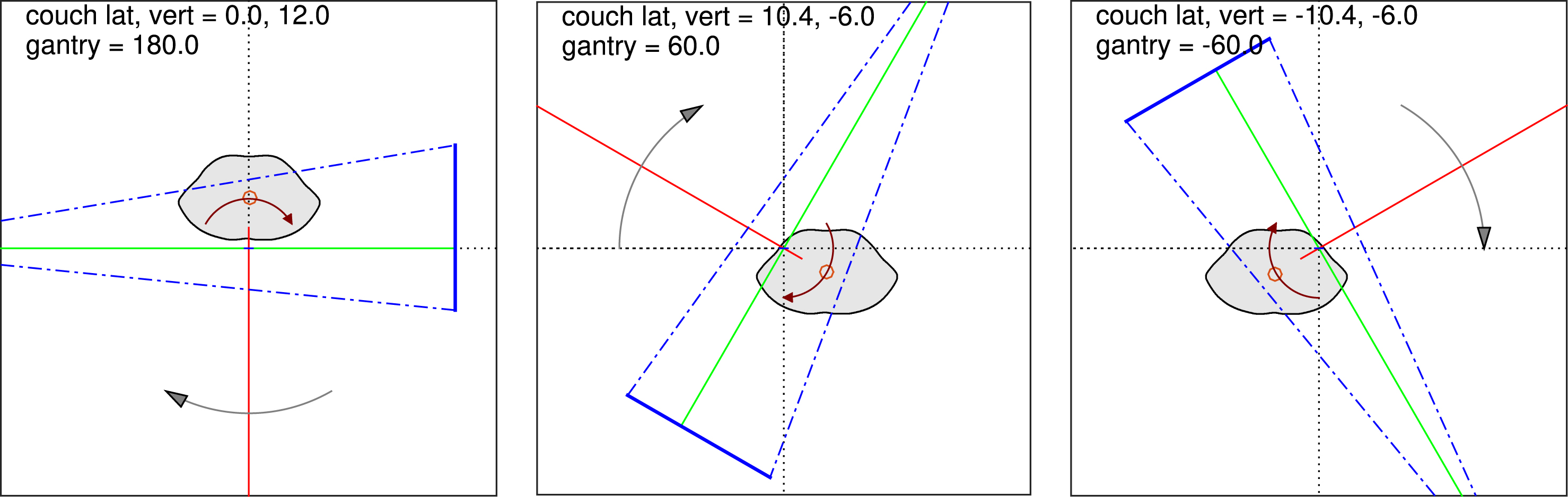
Patient, kV and MV beams, and kV detector (solid blue line) at several angles during a virtual isocenter rotation. Room coordinate system (dotted axes) has its origin at mechanical isocenter, and coincides with the intersection of the MV (red) and kV (green) beam axes. As the gantry rotates (direction indicated by black arrow), the patient (filled contour) is continually shifted to maintain a specified distance along the MV beam direction between the mechanical isocenter and the chosen virtual isocenter (circle symbol within the patient). The path of the virtual isocenter is a circle about the mechanical isocenter, with radius equal to the chosen shift (12 cm from the isocenter in this example). Detector may or may not be shifted, as shown, depending on virtual isocenter position and patient geometry.
In a similar approach, the patient could be translated away from kV detector panel to avoid this potential collision. If this were done consistently throughout the scan, it would increase the magnification and reduce the field-of-view (FOV) of the scan. If collisions are a concern then a reduced FOV is likely undesirable and may cause truncation artifacts. Instead it would be preferable to increase the magnification only in an angular range around the collision point, such as the elbow in Fig. 1b, in order to maintain the FOV while avoiding the collision. Because the magnification increase will only be used for a limited range of gantry angles, this would result in a more demanding couch motion than the smooth circle of the virtual isocenter. We have instead chosen to move the imaging panel away by translating the arm which caries the kV detector on the Varian TrueBeam system.
Finally, we consider a hybrid of the two approaches, incorporating both a virtual isocenter for clearance with the treatment head and the dynamic magnification to clear the detector panel. In practice, the radius to the treatment head and the kV detector housing are nearly the same so the hybrid technique would be required in most situations.
With the additional motions for collision avoidance, the standard Feldkamp type reconstruction cannot be used directly. There has been previous work in developing analytic methods for reconstruction from non-circular and generalized trajectories [17–20]. However, we have chosen to apply an optimization-based approach, specifically the maximum-likelihood expectation maximization (MLEM) algorithm [6]. This is by no means the only algorithm that could be used with these imaging trajectories. However, MLEM is well studied, generally well behaved and relatively simple with little dependence on the selection of algorithm parameters. These characteristics make it a practical choice for evaluating the suitability of non-standard image acquisition trajectories while providing comparable image quality to the current standard.
Optimization-based reconstruction algorithms provide a straightforward means of incorporating patient-specific collision avoiding trajectories [3, 10]. The imaging model is formulated as the linear transform
The projection data were acquired on a TrueBeam (Varian Medical Systems, Palo Alto, CA) using the linac-mounted CBCT c-arm system consisting of a Varian kV x-ray source (GS-1542) and a 39.7 cm × 29.8 cm amorphous silicon flat-panel detector (PaxScan 4030CB). The source and detector are mounted on robotic arms with the kV beam direction orthogonal to the MV treatment beam.
Various collision-avoiding scanning trajectories were implemented using Varian’s TrueBeam 2.0 Developer Mode whereby XML files are used to define control points for the gantry, the kV imaging arms, and the patient treatment table. This is a research mode of the TrueBeam system that allows scanning configurations that are unavailable in clinical modes by programming the motions of the gantry, couch and kV imaging arms. Although projection images can be acquired while both the treatment table and the gantry are in motion, simultaneous motion of the gantry and kV imaging arms is not currently possible. We have worked around this limitation in our variable magnification imaging as described in Section 2.4 below.
Phantoms
To quantify image quality metrics, we used a Catphan 504 (The Phantom Laboratory, Salem, NY), a standard quality assurance (QA) phantom for clinical CT devices that provides a series of sections with different objects for calculating image quality metrics. We used the CTP 404 module for evaluating low-contrast resolution, and both the CTP 404 and 528 modules for evaluating spatial resolution.
The abdominal region of the CIRS (Computerized Imaging Reference Systems, Norfolk, VA) model 600 torso phantom was also scanned. This phantom contains both high-contrast (bone) and low-contrast (soft tissue) structures in an anthropomorphic form. These features provide an indication of imaging performance in more clinically relevant conditions.
The manufacturer supplied IsoCal phantom (Varian Medical Systems) was used for geometric calibration of the imaging trajectories. This phantom is comprised of 16 tungsten-carbide spherical fiducials in a precise pattern on the surface of a 23 cm diameter hollow plastic cylinder.
Scanning Trajectories
Reference scans were acquired with a standard circular trajectory and a full gantry rotation (i.e., 360°). The Catphan was scanned with both a symmetric detector (full-fan) and an offset detector (half-fan) configuration. The anthropomorphic phantom was scanned only with the offset detector as the large field-of-view is needed to to cover the abdomen. The results shown will focus on the offset detector as the larger field-of-view is more likely to be necessary in situations where collisions are a concern.
The virtual isocenter trajectory, as described above in Section 2.1, provides additional clearance from the MV treatment head. In Fig. 2 this trajectory is shown in the room coordinate system with the treatment target (red circle) shifted along MV beam direction (red line) away from the treatment head. A 12 cm shift was used for the phantom scans which increases the clearance distance for the MV treatment head from 41.7 cm to 53.7 cm. This additional separation is maintained by the couch moving in a circle synchronously with the gantry rotation. The couch position was parameterized as a function of the gantry angle and sampled at approximately 180 control points to generate the Developer Mode XML control files. The detector offset was set to account for the couch position and provide the same FOV as the standard circular scans. The determination of this offset is covered in Section 2.5.
In all standard CBCT imaging modes the kV detector is located 50 cm from the axis of rotation resulting in an image magnification of 1.5× and approximately 44.4 cm of clearance from the isocenter. To increase clearance the mechanized arm that carries the detector panel can move to increases the image magnification. If the entire scan is performed with the increased magnification the reconstructable FOV will be reduced. To maintain the FOV, the image panel is moved only for the gantry angle range necessary to avoid collision.
To create the combined sinogram of a simulated collision-avoiding dynamic magnification scan, we replaced a 45° region of the 1.5× circular scan with the corresponding angular range from scans at different magnifications. This region was chosen to correspond with the position of the mannequin’s elbow in Fig. 1. Increasing the magnification in this region corresponds to increasing the clearance between the kV-detector and the patient. Increasing the magnification to a factor of 1.6× and 1.7× provides an additional 10 cm and 20 cm of clearance, respectively. We also created a variant of the dynamic magnification trajectory which includes a 5° intermediate transition at 1.6× on either side of a 35° region at 1.7×.
The resultant clearance radii for the virtual isocenter and dynamic magnification trajectories are shown in Fig. 3. The standard clearance for the MV linac head and kV detector panel are similar, 41.7 cm and 44.4 cm respectively. As such, a collision concern is likely to include both components. The final set of trajectories considered here is a hybrid that combines the virtual isocenter couch motion and the dynamic magnification to provide clearance from both linac components. The full set of trajectories and the clearance provided is listed in Table 1.
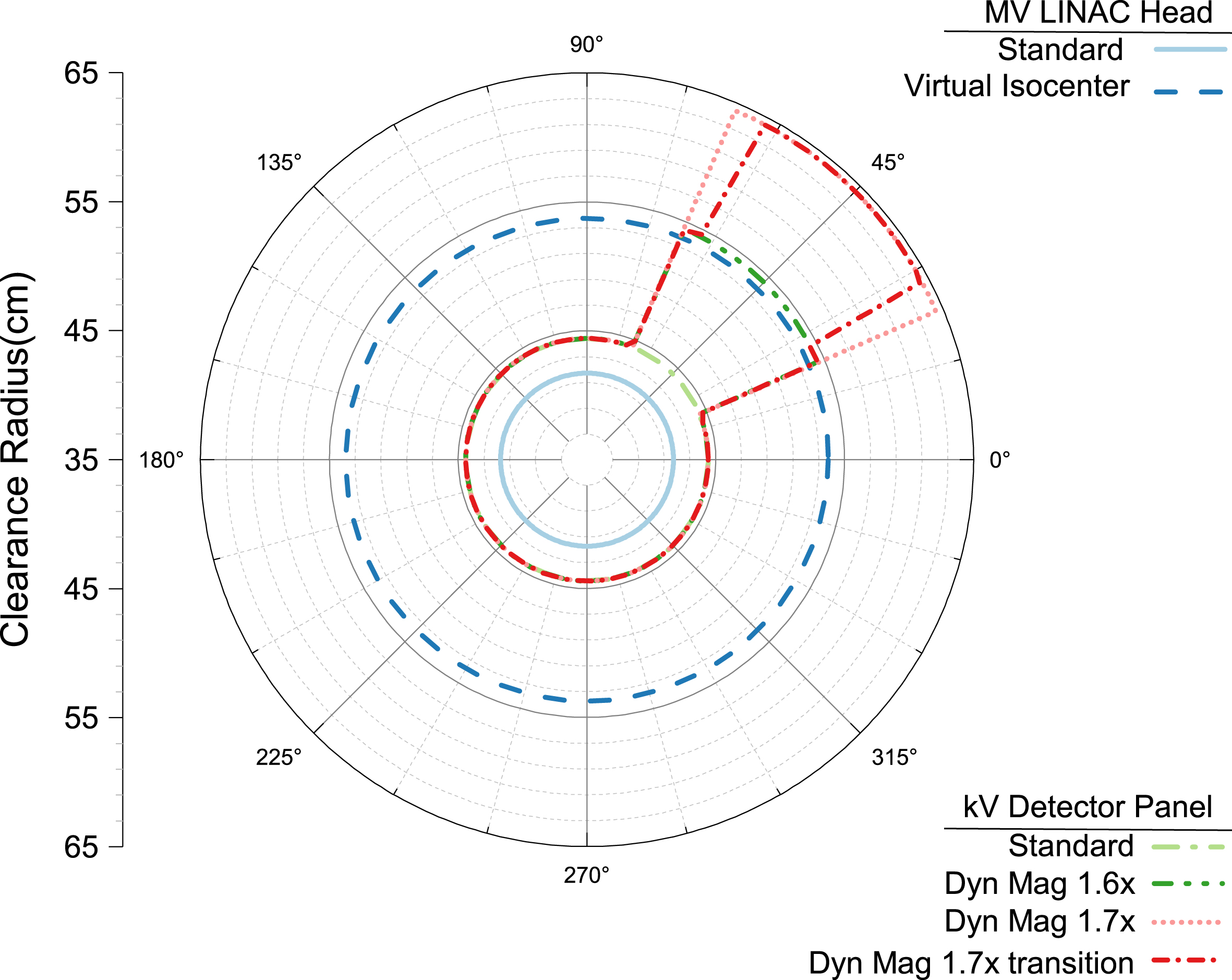
The clearance distance (as a radius from the imaging isocenter) for the MV linac head and the kV detector panel for the virtual isocenter and dynamic magnification trajectories. The virtual isocenter trajectory used here has a 12 cm offset from the mechanical isocenter and increases the MV head clearance from 41.7 cm to 53.7 cm. The dynamic magnification trajectories were planned with a 45° clearance region corresponding to the elbow position in Fig. 1. The 1.5×, 1.6× and 1.7× magnifications result in clearances of 44.4 cm, 54.4 cm and 64.4 cm, respectively (see Table 1).
A common CBCT scanning configuration uses a detector that is symmetric about the central ray of the beam. This allows the scan to be acquired with a little more than a half rotation, but the field of view is limited by the size of the detector panel as shown in Fig. 4a. For the TrueBeam system this is referred to as a full fan scan and is primarily used for cranial imaging. An alternative is to offset the detector to one side of center which then requires a full 360° rotation but allows the field-of-view to be increased as shown in Fig. 4b. This is referred to as a half-fan geometry and is the default for most of the thoracic, abdominal and pelvic clinical imaging protocols.
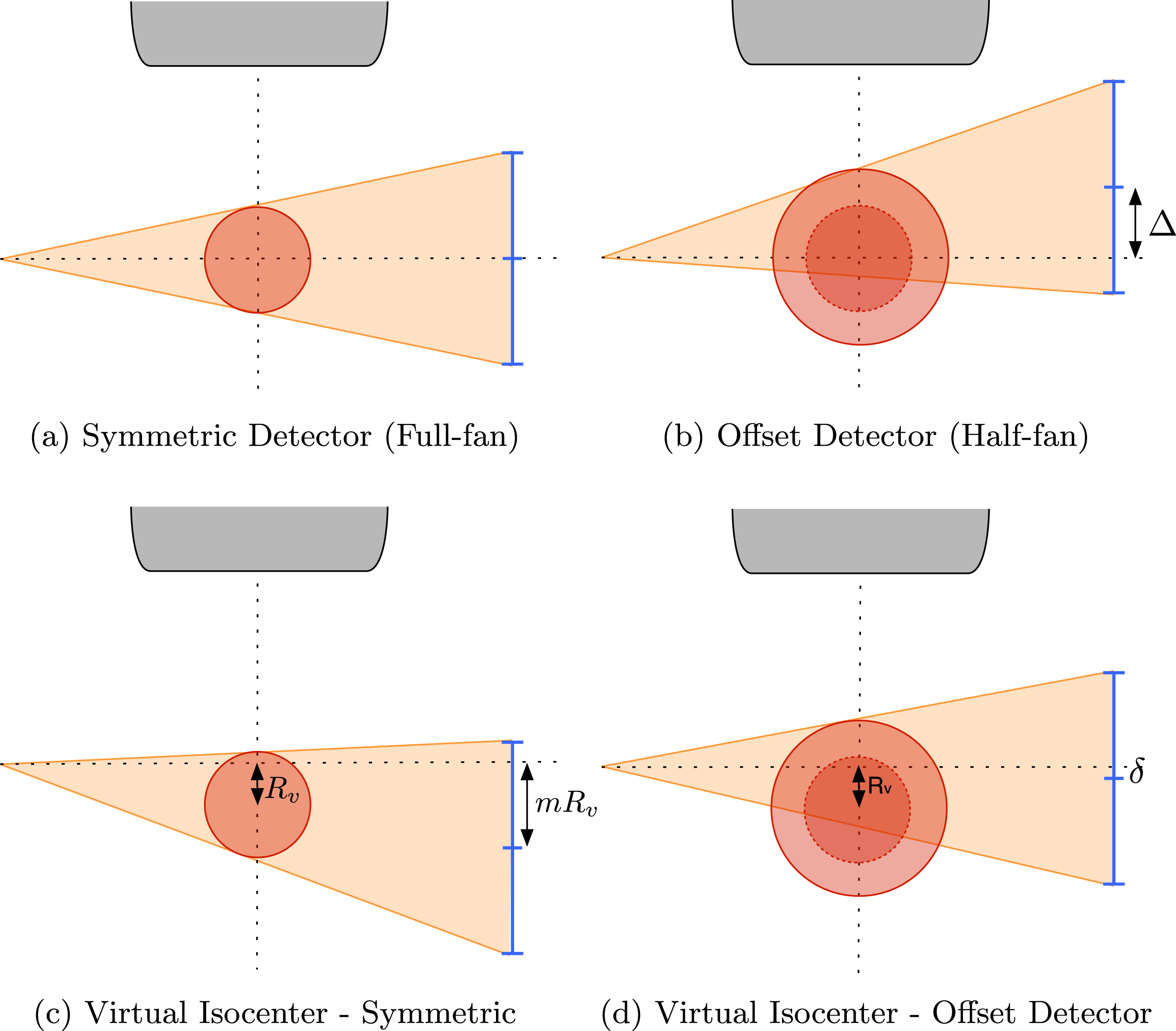
The full-fan acquisition geometry in (a) with the red circle indicating the FOV, blue lines the kV detector panel and the linac in gray at top. In (b) the half-fan geometry with the lateral offset (Δ) detector to increase the FOV (original shown as dotted circle). In a virtual isocenter acquisition (c) the patient is moved away from the linac head by an amount R v and the detector panel must be shifted to accommodate by mR v where m is the image magnification. To increase field-of-view of the offset detector in (b) with a virtual isocenter, both shifts must be included in a combination shown in (d) where the offset δ = mR v - Δ.
As shown in Fig. 4c, using a virtual isocenter at a distance R
v
from the mechanical isocenter results in the virtual isocenter projecting to a different location on the detector. Thus, to achieve the same field-of-view as a full-fan geometry the detector must be shifted by a corresponding amount mR
v
to compensate, where m is the image magnification. To obtain an equivalent field-of-view as the half-fan scan with a virtual isocenter trajectory, the resultant shift is a combination of the two
To find an estimate of the object
In the IGRT context, the image array
This requires a corresponding change in the system matrix
We reconstructed all of these fixed magnification and dynamic magnification scans from circular and virtual isocenter trajectories into the patient image space described by the imaging model in Equation 5. The Catphan scans were reconstructed onto an isotropic voxel size of 0.473 mm. The CIRS torso scans were reconstructed onto an isotropic voxel size of 0.836 mm. As the circular acquisition with 1.5X magnification is the typical clinical acquisition trajectory, it was used as the clinical reference volume for comparison to the reconstructions from the other scanning configurations.
With any iterative reconstruction algorithm, one of the parameters that must be chosen is the stopping point in the iterative process, as convergence is seldom reached in practice. As MLEM progresses toward the designed solution, details emerge gradually and resolution improves. The structural changes eventually become smaller, only affecting the noise texture at which point the changes are generally detrimental. From this experience, we used a measure of image sharpness taken from the edge of the Catphan in the image to determine a fixed number of iterations to be used in all subsequent reconstructions. Figure 5 shows the 25% and 50% MTF crossing spatial frequencies and the MTF area under the curve (AUC) generated from the edge spread function from the MLEM reconstruction of the Catphan phantom acquired with a circular scan at 1.5X magnification. These three metrics, used as simple indicators of the changes in the full MTF curve, behave similarly and follow the qualitative observations described previously. Based on this result, 200 iterations of the MLEM algorithm was selected as the stopping point for all reconstructions.
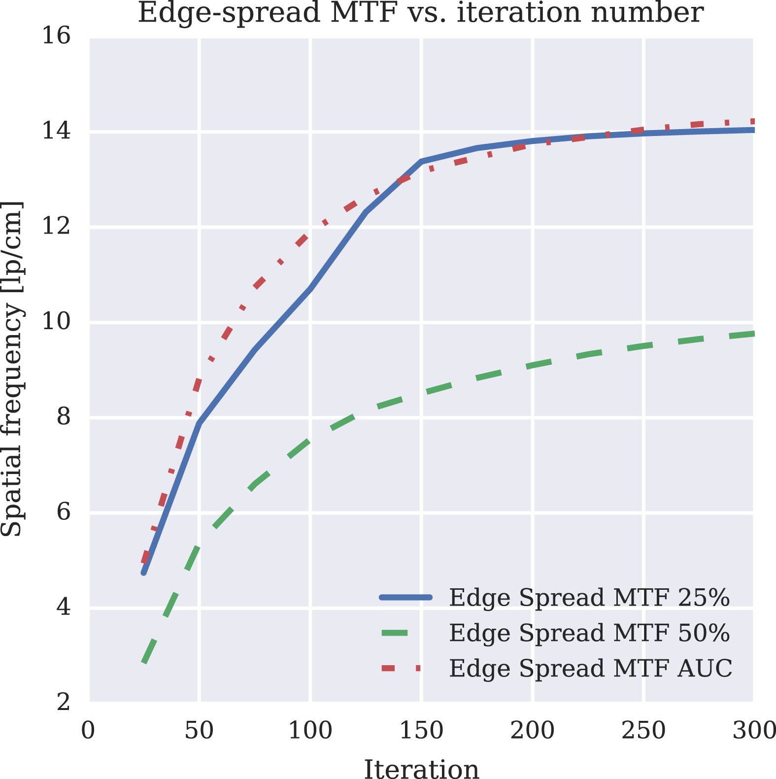
Plot of the Catphan’s edge-spread function MTF at 50% and 25% as well as the MTF AUC for the clinical circular 1.5X half-fan scan.
The standard geometry calibration performed on the clinical machines is not intended for imaging trajectories with dynamic motions of the couch and imaging arms. As such, the complexity of motions for these trajectories required an additional geometric calibration to measure deviations from the planned ideal trajectory. There are many solutions to the geometry calibration problem that have previously reported [16, 38]. This work used an in-house developed method based on a standard iterative solver to find the camera view parameters using a calibration scan of a standard phantom but any method that provides a good estimate of the view parameters would work.
An optimization-based calibration protocol utilizing Varian’s Isocal calibration phantom was developed to extract calibration offsets for improving the estimate of the system matrix
Metric Evaluation
To compare the different magnifications of both the circular and virtual isocenter trajectories to the MLEM reconstruction of a standard circular scan, we used the sensitometry and spatial resolution modules (CTP 404 and CTP 528 respectively) of the Catphan phantom. Additionally, the HU accuracy and similarity of the reconstructed images to the standard reference were evaluated for the anthropomorphic torso phantom.
Catphan spatial resolution metrics
There are a number of ways to evaluate the spatial resolution from images of the Catphan phantom in a CT image. The CTP528 module contains a circular array of bar patterns which was used to determine the highest frequency set that is visually resolvable. The same module also has two 0.28mm tungsten carbide beads simulating an impulse source from which a point spread and then a modulation transfer function (MTF) can be determined [8]. Furthermore, the MTF can be calculated from the bar patterns themselves [7], as well as any suitably high contrast edge in the image [28].
While the use of MTF in CT has its challenges, notably the assumption of shift-invariance is not satisfied, it still can be useful when treated with some care. Each of the methods above has some advantages and disadvantages. The point source method can provide 3D directional estimates of the point-spread function (PSF), however it can also be sensitive to the location of the bead relative to the image grid with significant difference between a bead located totally within a single voxel or at the interface of many voxels. We used MTF only to make relative comparisons between the imaging trajectories with all other aspects held constant.
While the bar pattern based evaluation is complementary to the visual analysis, the orientation of the bars relative to the grid will affect some frequencies differently than others which can result in atypical MTF curves. Using an edge spread analysis on the circular phantom boundary provides many samples, at varying directions to the image grid which can be averaged out. Although it could be impacted by scatter or saturation in the air region near the phantom boundary, this has not proven to be a significant factor in the images we analyzed.
Low-contrast resolution metrics
To characterize low-contrast resolution, we calculated the contrast-to-noise ratio (CNR) using the polystyrene insert in the CTP 404 sensitometry module. These inserts have CT numbers which are the closest to the water-like polymer that surrounds them. The metric is defined as
The last metric evaluated was the reproducibility of the CT numbers between the various trajectories. Regions-of-interest (ROIs) were drawn in the plastic rods of the CTP 404 sensitometry module of the Catphan as well as regions corresponding to the aorta, liver and spleen in the anthropomorphic phantom. The distributions of these values for all collision avoiding trajectories were compared to the standard circular scan (i.e. reference).
Image Similarity
The reconstructions of the anthropomorphic torso phantom were compared to the reference scan with several common metrics of image similarity. First, the root mean square error (RMSE) is computed for a region of the image containing the complete phantom. The multi-scale structural similarity (MSSIM) index [34, 35] is a quantitative measure of image similarity designed to be representative of human perception. The index ranges from -1 to 1, where an image compared to itself results in a score of 1. Finally, visual image fidelity [29] is another measure of similarity intended to correspond with human perception. On this scale, a score of 0 indicates all information is lost from the image and 1 that it is identical to the reference.
Results
Catphan spatial resolution metrics
Figure 6 shows axial views of the CTP 528 spatial-resolution module from the 200th iteration of the MLEM reconstructions of the Catphan phantom for the different scanning trajectories. The top row shows reconstructions from the circular scanning trajectories, and the bottom row shows reconstructions from the virtual isocenter trajectories. The left column is from a single 1.5X magnification, and the remaining columns are different synthesized trajectories with different magnifications as illustrated in Fig. 3. In all of these images, the 8th largest gauge, indicated by the red arrow, is visually resolvable.
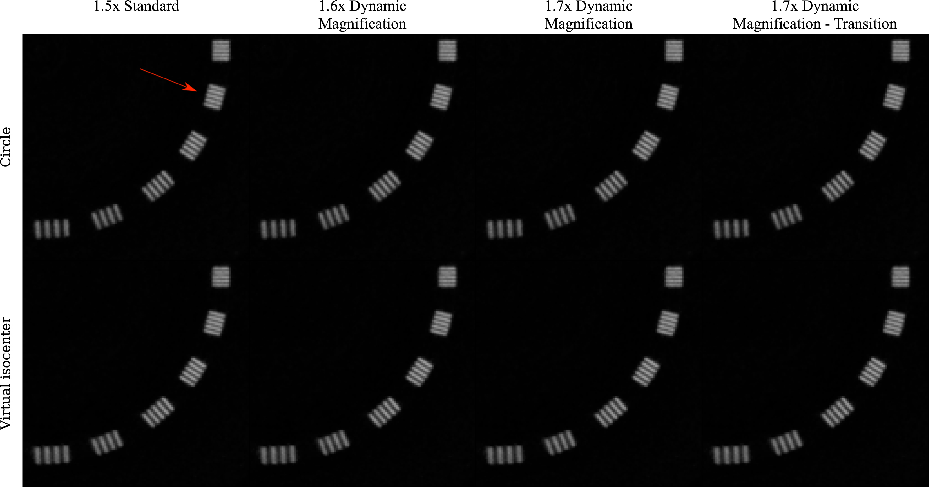
Images of the Catphan 528 spatial resolution module in a display window of [-100, 2000] HU. The top row shows all the circular scan permutations while the bottom row shows those of the virtual isocenter. The columns show different magnification combinations. For all of the reconstructions, the 8th largest gauge is resolvable (indicated by the red arrow).
The visual similarity in the spatial resolution shown in Fig. 6 is reflected in the MTF metrics for all of the different scanning configurations. We compared MTF metrics derived from the PSF using the Catphan beads, the bar pattern shown in Fig. 6, and the edge-spread function (ESF) measured along an ensemble of radial lines. When comparing these MTF-based metrics between the circle and the virtual isocenter scans with different magnifications, we found no clear trend distinguishing the different trajectories.
The low contrast resolution was evaluated as the contrast to noise (CNR) ratio between the polystyrene insert which has a nominal expected HU range of -65 to -29 and the water equivalent background with nominal HU range of -7 to 7 [8]. These values are plotted for all considered trajectories in Fig. 7, where the reference is the circle at 1.5× magnification, or leftmost blue dot. The bars on the plot represent ±1 standard deviation. Nearly all points fall within this range indicating no substantial CNR penalty for the collision avoiding trajectories.
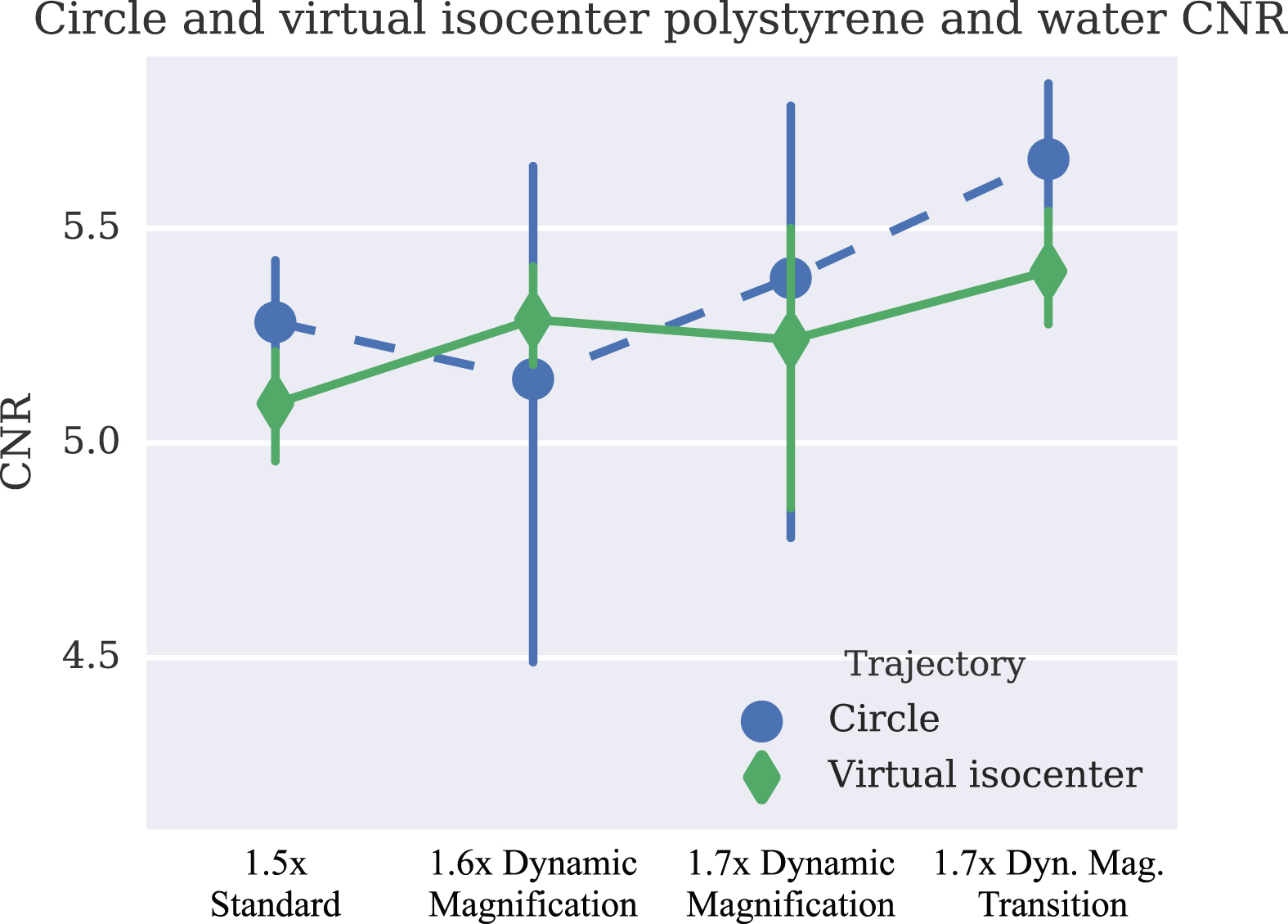
Plot of low-contrast CNR and error bars corresponding to ± one standard deviation of the CNR from the Catphan scanned with both the circular and virtual isocenter trajectories.
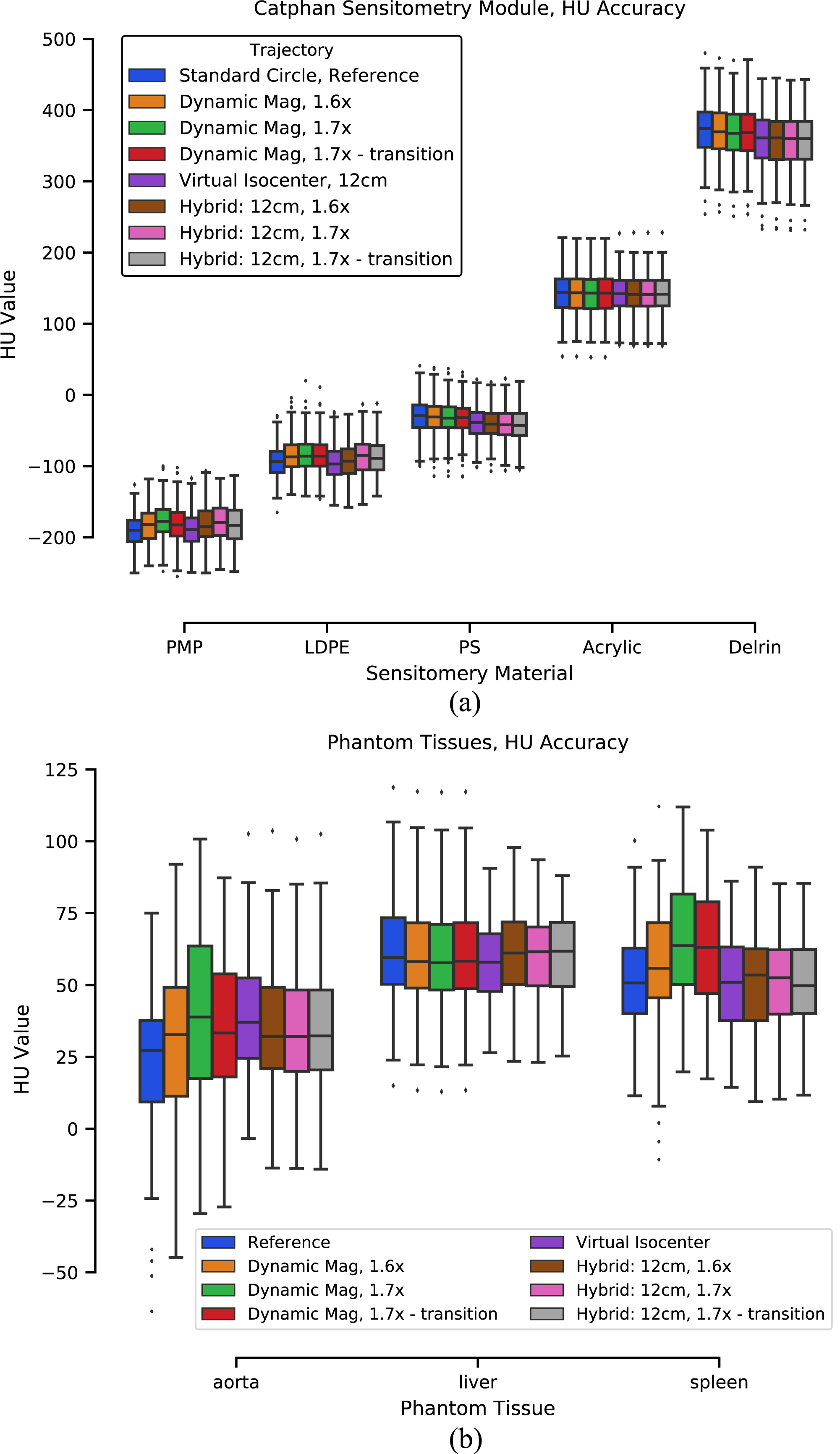
Image values from ROIs in a selection of materials from the CTP404 sensitometry module of the catphan (a) and organs of the torso phantom (b) plotted in standard box and whisker form. The ROI locations for the torso phantom are shown in Fig. 9. The standard reference scan is the first bar for each ROI, in blue. The order of all trajectories matches the order they appear in the legend.
The quantitative accuracy of the reconstructions from collision avoiding trajectories was evaluated by comparing the distribution of CT values taken from regions of interest in different homogeneous materials. Figure 8 shows these results for a selection of the inserts from the CTP 404 sensitometry module of the Catphan as a standard box plot. Figure 8 similarly plots the values from regions corresponding to the aorta, liver and spleen in the torso phantom. Locations of these ROIs are indicated in Fig. 9. The box plots from both the Catphan and torso phantom results show some variations in the mean values but generally stay within the interquartile range. Furthermore, across material types no consistent trends in the variations are evident, suggesting that the various trajectories provide comparable CT number accuracy.
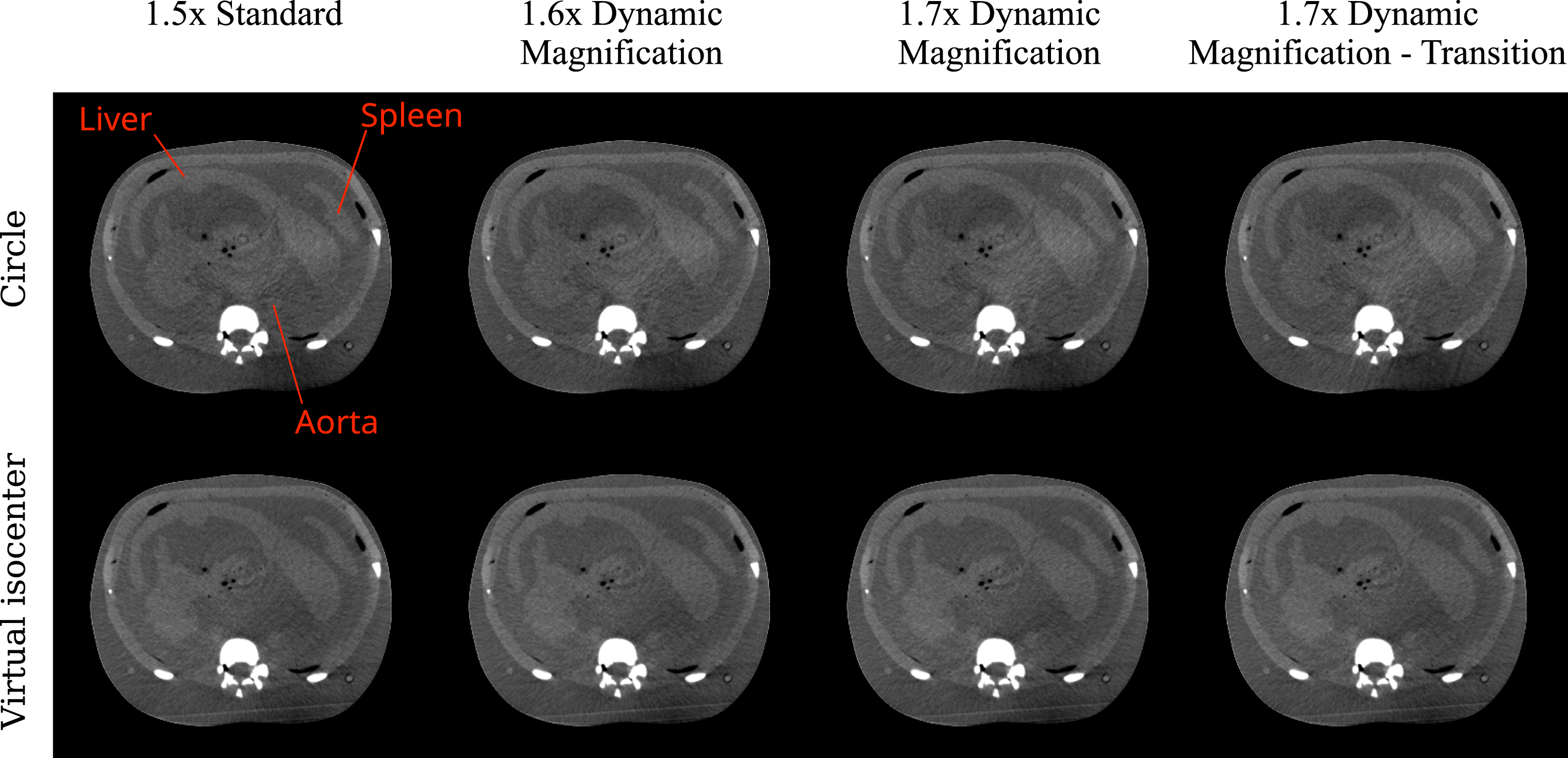
Images of the CIRS torso phantom’s abdomen in a display window of display window of [-200, 500] HU. The top row shows all the circular scan permutations while the bottom row shows those of the virtual isocenter. The columns show different magnification combinations from left to right.
Figure 9 shows an abdominal slice from the 200th iteration MLEM reconstruction of the CIRS torso phantom scanned with a 13 cm offset half-fan configuration. The layout of these images is the same as that in Fig. 6 with the top row showing magnification variations from the circular trajectory. The bottom row shows the corresponding magnifications from the virtual isocenter trajectory. This is the axial view from which HU values were calculated in Fig. 8. Visually, comparable image quality is achieved regardless of the scan trajectory used.
Results from the quantitative comparison of the collision avoiding trajectories to the reference scan are listed in Table 2. The RMSE is calculated on the linear attenuation values prior to applying the HU calibration. The 10-4 scale of these values is small compared to the attenuation of most tissues. Both the MSSIM and VIF similarity metrics have values near 1 for all trajectories indicating that the collision avoiding trajectories perform similarly to the current standard.
Quantitative comparison of the reconstructed images of the torso phantom from Fig. 9, the reference for each comparison is the standard circular trajectory with 1.5× magnification. The first column is the root mean square error (RMSE). The second is the multi-scale structural similarity (MSSIM) index [35]. The MSSIM index ranges from –1 to 1 where an image compared to itself yields 1. The final column is visual image fidelity [29], which ranges from 0 (all information lost) to 1 (all information preserved)
Quantitative comparison of the reconstructed images of the torso phantom from Fig. 9, the reference for each comparison is the standard circular trajectory with 1.5× magnification. The first column is the root mean square error (RMSE). The second is the multi-scale structural similarity (MSSIM) index [35]. The MSSIM index ranges from –1 to 1 where an image compared to itself yields 1. The final column is visual image fidelity [29], which ranges from 0 (all information lost) to 1 (all information preserved)
The described virtual isocenter, dynamic magnification and hybrid trajectories are designed to enable acquisition of CBCT scans in patients for which the standard circular trajectory may not be possible due to potential collision issues. The motions required to provide the additional clearance present several challenges for acquiring, processing and reconstructing the data. To our knowledge, this is the first demonstration of feasibility of these non-circular CBCT trajectories for collision-avoidance. The results showed that the virtual isocenter, dynamic magnification and hybrid trajectories can all provide image resolution, contrast, and HU accuracy comparable to those of the standard circular trajectory.
All scanning in the present work was done in TrueBeam Developer Mode, which is a strictly nonclinical mode of operation. The system is currently capable of the synchronized couch and gantry motions required for the virtual isocenter component of the trajectories. For the 12 cm virtual isocenter extension studied here, the couch moves through a 24 cm diameter circle in one minute which is relatively slow and can be accomplished without extending the acquisition time. It is expected that this slow, smooth motion would easily be tolerated by most patients but this has not yet been studied.
Currently, Developer Mode does not support synchronized movement of the imaging arms so implementing the dynamic magnification component would require stopping the gantry while moving the detector arm which would extend the scan time. This would be clinically detrimental as the long scans times risk a loss in image quality due to increased motion artifact. However, it is anticipated that with a future update the control system could allow fully synchronized motions.
One potential limitation of the technique is that it is not directly compatible with the standard bowtie filter, which has been shown to be beneficial for image quality and imaging dose [9]. Work has also been done on developing dynamically shaped compensators [11, 32] that would be compatible with these non-standard techniques and may further improve image quality and/or reduce dose.
To reconstruct images from the described trajectories, the MLEM algorithm was used. This algorithm is not unique in being able to handle these trajectories. However it is simple, well studied, and has few parameters while providing a good indication of the usability of these trajectories for imaging patients that would present collision concerns for the standard circular conebeam trajectory. A common concern regarding optimization-based methods has been reconstruction time. These are more computationally demanding than standard filtered back-projection methods, but with the continuing advance in GPU processing power, reconstruction times are becoming manageable.
Conclusion
Virtual isocenter trajectories and dynamic magnification are potentially useful as collision-avoiding alternatives to standard circular scans. Each provides additional clearance from the machine components, which may be used to scan patients without potential collisions that may otherwise have precluded imaging. Results from anthropomorphic and geometric, quality-assurance phantoms demonstrate that these trajectories provide image quality comparable to the standard circular conebeam CT scan.
Footnotes
Acknowledgments
Funding was provided in part by Varian Medical Systems, the Lawrence H. Lanzl Fellowship (to A. D.), and NIH Grants R01 CA182264, R01 EB018102, S10 RR021039 and P30 CA14599. We are grateful to Pascal Paysan and Dieter Seghers (also Varian) for providing and assisting with the iTools Reconstruction software. The contents of this work are solely the responsibility of the authors and do not necessarily represent the official view of any of the supporting organizations. The authors have no relevant conflicts of interest to disclose.