
Abstract
BACKGROUND:
Versa HD linear accelerators (linacs) are used for stereotactic radiosurgery treatment. However, the mechanical accuracy of such systems remains a concern.
OBJECTIVE:
The purpose of this study was to evaluate the accuracy of an Elekta Versa HD linac.
METHODS:
We performed measurements with a ball bearing phantom to calculate the rotational isocenter radii of the linac’s gantry, collimator, and table, and determine the relative locations of those isocenters. We evaluated the accuracy of the cone-beam computed tomography (CBCT) guidance with a film-embedding head phantom and circular cone-collimated radiation beams. We also performed dosimetric simulations to study the effects of the linac mechanical uncertainties on non-coplanar cone arc delivery.
RESULTS:
The mechanical uncertainty of the linac gantry rotation was 0.78 mm in radius, whereas that of the collimator and the table was <0.1 mm and 0.33 mm, respectively. The axes of rotation of the collimator and the table were coinciding with and 0.13 mm away from the gantry isocenter, respectively. Experiments with test plans demonstrated the limited dosimetric consequences on the circular arc delivery given the aforementioned mechanical uncertainties. End-to-end measurements determined that the uncertainty of the CBCT guidance was≤1 mm in each direction with respect to the reference CT image.
CONCLUSIONS:
In arc delivery, the mechanical uncertainties associated with the gantry and the table do not require remarkable increases in geometric margins. If large enough, the residual setup errors following CBCT guidance will dominate the overall dosimetric consequence. Therefore, the Versa HD linac is a valid system for stereotactic radiosurgery using non-coplanar arc delivery.
Introduction
Linear accelerator (linac) based stereotactic radiosurgery (SRS) is an increasingly popular treatment modality for brain metastases and other similar types of brain lesions [1–4]. In SRS procedures, a very high radiation dose is delivered to a small target in a single fraction treatment. This is typically performed in a non-coplanar arc setting and guided by an integrated imaging system (e.g., cone-beam computed tomography or CBCT). Therefore, a sufficiently high level of accuracy in both mechanical performance and image guidance is required to perform SRS procedures. Numerous recent investigations have commented on the dosimetric characteristics [5–9], mechanical uncertainties, and image guidance accuracy [10–15] for linac based SRS. Nevertheless, most of these studies focused on the evaluation of a specific aspect of linac based SRS systems, such as small field measurement, imaging fusion accuracy for target localization, or the discussion on the choice of detectors or circular cones. In this work, we intend to evaluate an entire radiation delivery platform for linac based SRS.
Versa HD™ (Elekta AB, Stockholm, Sweden) is one of the most commonly used linacs for SRS delivery [16–18]. Our Cancer Institute recently installed three new Versa HD linacs. There is a plan to migrate the existing SRS program to one Versa HD linac. This linac is equipped with multiple photon energies, including a 6 MV flattening filter and 6 MV flattening filter free (FFF) photon energies, and also with an integrated kV CBCT system for image guidance.
During the acceptance tests, this linac exhibited gantry walkout of > 1.5 mm in diameter, which is consistent with the gantry walkout of the other two installed Versa HD linacs, and is also consistent with the observation of other Versa HD users [19]. These Elekta linacs exhibit slightly larger mechanical uncertainties (to be specific, during gantry rotation) than their counterparts. For example, the isocenter diameter of a TrueBeam platform (Varian Medical Systems, Palo Alto, USA) was 0.49 mm according to a previous study [20]. These larger uncertainties mainly result from the structural design of the Elekta linac gantry that must accommodate the tilted traveling-wave-based accelerating tube.
The magnitude of Versa HD gantry walkout raised concerns over the accuracy of SRS delivery on this system, and hence our plan for SRS program migration. The limited number of studies that investigated the dosimetric effect of the Versa HD mechanical uncertainties were identified in the literature. One such study mainly focused on the dosimetric effect caused by the gantry sag [21], but it did not study the dosimetric consequences due to other mechanical uncertainties such as collimator and table motion, where is very common in clinical SRS treatment. Therefore, this study was initiated in an attempt to evaluate the dosimetric consequences to SRS treatment resulted from the different types of mechanical uncertainties in a Versa HD linac. In this study, we first determined the mechanical uncertainties and the CBCT guidance accuracy of the Versa HD platform based on portal image and film measurements using a previously published calculation algorithm [20]. Then we evaluated the dosimetric consequences of these mechanical and image guidance uncertainties via simulations using our treatment planning system. We had to perform these simulations because in reality we were unable to produce “ideal” dose distributions.
To reflect reality, we used treatment plans with non-coplanar circular cone arcs in the dosimetric simulations, because non-coplanar arc delivery is one of the most common linac-based SRS dose delivery methods. The radiation beams for SRS are collimated with circular cones or a multi-leaf collimator (MLC). Intensity-modulated beams can be produced with a MLC; however, MLCs have their own issues, such as leaf movement uncertainty and source occlusion. Compared with MLCs, circular cones have sharper penumbra and others have suggested that they require slightly larger setup margins [22]. Therefore, conclusions derived from this study are clinically relevant and dosimetrically conservative.
Materials and methods
Linear accelerator
In the present study, we performed measurements on a Versa HD™ linac (SN 4127) with a HexaPOD™ 6D couch, which was installed at our institution in the spring of 2017. This linac uses an Agility™ multi-leaf collimator or circular cone collimators (Aktina Medical, Congers, NY) that are ready for SRS treatment. Aktina cones have different configurations from Elekta stereotactic cones; we measured their dosimetric characterization with the same methods described by previous investigators [18]. Prior to the measurements, Elekta service engineers calibrated the CBCT, and a medical physicist from Aktina Medical aligned the circular cones to the collimator rotation axis. We have used IEC 61217 coordinate conventions throughout this manuscript, i.e., the lateral, longitudinal, and vertical directions of the linac table are labeled with x, y, and z coordinates, respectively.
Linac isocenter measurement
The isocenter and axis of rotation (AOR) of the gantry, the collimator, and the linac table were determined using a method described previously [20]. Specifically, we first calibrated lasers in the linac vault during the Flexmap procedure [23], so that they may represent the linac radiation isocenter. Next, we placed a QUASAR™ IsoCenter Cube phantom (Modus Medical Devices Inc., London, Ontario) on the linac table and aligned it to the room lasers. A 14-mm cone collimator was mounted on the linac head. The linac gantry, collimator, and table were rotated in turn, with the other two systems remaining at the 0° angle. The rotation angles were at 10° or larger intervals; we took an image at each angle with the MV flat panel. Those images were acquired in a single session continuously without moving the Cube phantom or the linac tabletop. We analyzed the images using a previously published algorithm [20] to derive the coordinates and diameters of the gantry mechanical isocenter, the AOR of the collimator, and the AOR of the table with respect to the center of the ball bearing imbedded in the Cube phantom. Because the cone was mechanically calibrated, its center was regarded as the useful beam axis. Therefore, we considered the measured gantry isocenter to represent the linac radiation isocenter [24].
Localization with cone-beam CT guidance
We measured the phantom localization accuracy of the Versa HD linac in an end-to-end manner. First, we cut Gaf-chromic™ EBT2 film (Ashland Advanced Materials, Bridgewater, NJ) into 7.5 cm×7.5 cm squares and placed a piece of the film in a target/treatment verification film cassette, which in turn was secured in a Lucy 3D QA phantom (Standard Imaging Inc., Middleton, WI). The Lucy phantom was leveled on the CT scanner table with its head towards the gantry and the film facing up (AP setup) or left (LL setup), as shown in Fig. 1. We scanned the phantom five times for each film orientation using an SRS protocol (slice thickness and pixel size, 1 mm).

A Lucy phantom is secured on a Versa HD linac table (left) and aligned to the room lasers (right). The film cassette (red arrow) is in place with film facing up.
The CT images were imported to iPlan® (iPlan Net 3.5.0, BrainLab AG, Munich, Germany) treatment planning system, and one test treatment plan was generated for each CT image dataset. Prior to the present study, the Versa linac was commissioned in iPlan for treatment planning purposes. Small field dosimetry data were included per BrainLab’s instructions. A static 6 MV beam using a 5-mm cone was placed perpendicular to the film, with the beam isocenter placed roughly at the geometric center of the Lucy phantom. The Lucy phantom was mounted on the linac table, and a CBCT scan was performed with the built-in “fast head and neck” protocol. Table translational shifts and rotational angles were determined by the image guidance system with respect to the predetermined isocenter in the test plan; the HexaPOD™ 6D couch positioned the Lucy phantom until the target translational and rotational values were achieved. Then the phantom was irradiated with 500 monitor units (MU) for sufficient film exposure at 0° (AP setup) or 90° (Left Lateral setup) gantry angles. The end-to-end CBCT guidance accuracy was evaluated by comparing the beam center on the film (Fig. 2) and the beam isocenter in the treatment plan with respect to the four sharp marker pins in the film cassette.
For both AP and LL setups, we aligned the Lucy phantom on the linac table in two ways: (1) arbitrary 2° rotations about the x-axis, y-axis, and both axes, and (2) no arbitrary rotations but with random small translations (range, 0-1 cm). For each phantom scan or alignment with rotation, a group of five films was irradiated to assess the accuracy of CBCT guidance. We performed a two-tailed t-test to examine whether the relative beam center coordinates of the first group (designated as CT_AP1 or CT_LL1) were different from that of the other groups with arbitrary rotations or with the same setup (AP or LL). When applicable, we reported the values in the format of mean±standard deviation; a p-value of <0.05 is considered statistically significant.
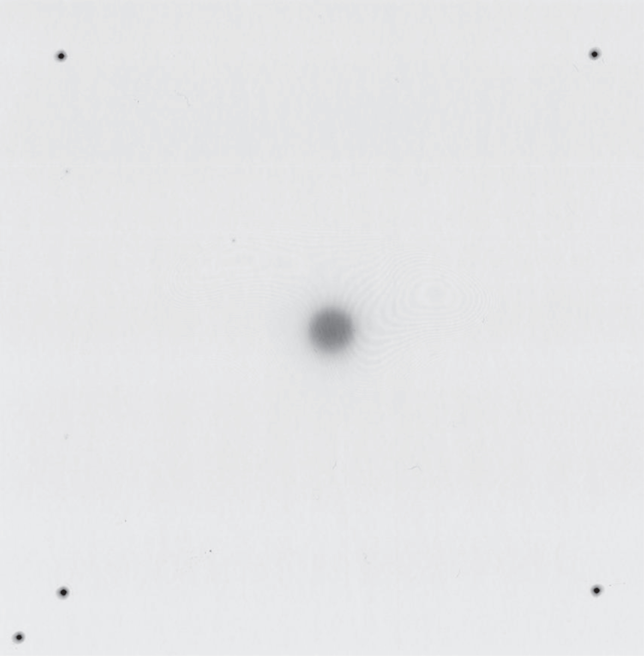
An irradiated film with the image of the circular cone at the center, and the marks of the sharp pins at the four corners. The fifth pin helps determine the film orientation.
The dosimetric effects of gantry mechanical uncertainties on the circular arc delivery were simulated using iPlan. A 14-cm diameter water equivalent sphere was created in the treatment planning system, and circular arc plans were produced with 6 MV FFF energy for cones of 5 mm, 10 mm, and 14 mm diameters. Each plan had two opposite coplanar arcs using the same cone in order to generate a symmetric dose distribution for analysis. Each arc spanned 120°, a typical arc length in SRS treatment. Specifically, the start and stop angles of the gantry were 30° to 150° and 210° to 330°, respectively. Each arc delivered 1200 MU (100 MU per 10°). For comparison, the arcs in the set of “ideal” plans used a common isocenter located at the center of the sphere; we added isocenter shifts to the arcs in the other plans every 10° according to the measurements described in Section 2.2. We evaluated the dosimetric changes that resulted from the mechanical uncertainties with the various isodose volumes and Paddick’s gradient index [25, 26]. Paddick’s gradient index is defined as the ratio of the volume of half the prescription isodose to the volume of the prescription isodose (i.e., GI = V50 %/V100 %). In this study, the prescription isodose was arbitrarily chosen as 70% of the maximum point dose in the ideal plan because this isodose level is associated with the best normal tissue sparing [27].
Dosimetric effects of setup and table rotation uncertainties
We also simulated the dosimetric effect on the circular arc delivery caused by patient setup uncertainties in iPlan. Ideal treatment plans representing accurate patient setup without mechanical uncertainties had four non-coplanar circular arcs on the common isocenter located at the center of the 14-cm sphere with table angles 40° apart. In the plans simulating residual setup errors, we arbitrarily moved the sphere in the x, y, and z directions. Simulation plans were produced for 0 mm, 0.5 mm, 0.75 mm, and 1.0 mm shifts using 6 MV FFF energy. Also, to study how the dosimetric effects vary with cone sizes under the same set of setup errors, these simulations were repeated for three cone diameters: 5 mm, 10 mm, and 14 mm. In these plans, all arcs spanned 120° as previously described. We assessed the dosimetric effect by the shifts of the 70% isodose volume. Similar simulations were also performed for table rotation uncertainties, in which each of the four arcs had its isocenter, with these isocenters aligning on an arc of 0.5 mm radius, slightly larger than the measured table AOR radius (see the next section).
Results
Linac mechanical uncertainties
The measurements using the cube phantom showed that the AOR of the collimator coincided with the gantry isocenter, and the table AOR was 0.13 mm away. The radius of the collimator AOR was 0.04 mm, the radius of the table AOR was 0.33 mm, and the radius of the gantry isocenter was 0.78 mm. When the gantry rotated, the beam axis shift roughly resembled a sinusoidal function in the longitudinal direction, towards and away from the linac gantry (Fig. 3). The beam axis shifted similarly in the other two directions at smaller magnitudes.
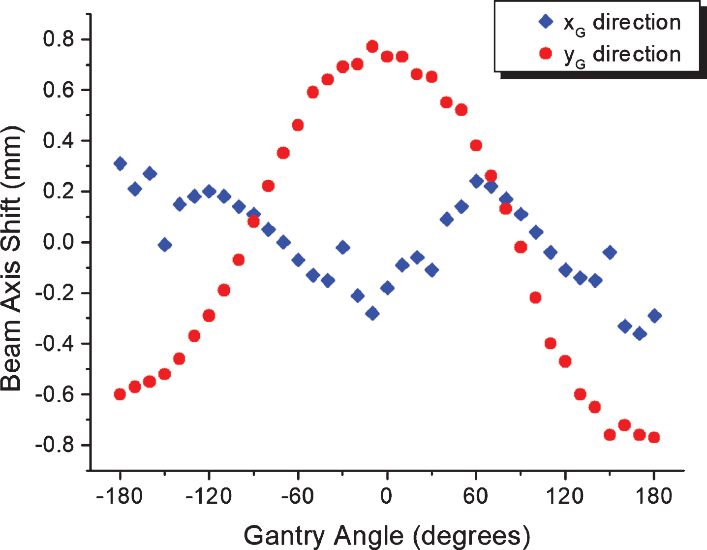
Beam axis shift of a circular cone in the linac gantry coordinate system as function of the linac gantry angle. The coordinate XG is perpendicular to the gantry rotation axis, and the coordinate YG is along the axis (table longitudinal direction).
Eighty pieces of EBT2 film were irradiated for the assessment of CBCT-guided Lucy phantom localization. Table 1a and 1b show the results comparing CBCT guidance accuracy with and without arbitrary phantom rotations for the AP and LL setups, respectively. Table 1c and 1d show the results of CBCT guidance accuracy for different CT simulation scans for the AP and LL setups, respectively. In these tables, each CT simulation is labeled with its orientation and serial number. These data confirm that the end-to-end phantom localization accuracy on this linac system is within 1 mm in each direction. Relative to the reference CT images (CT_AP1 and CT_LL1), there is no clear indication that either CT simulation scans or phantom rotations/translations would result in significant differences in CBCT localization accuracy, although most p-values in Table 1d are smaller than 0.05. For the AP setup, the grand averages of localization errors were x = –0.71±0.13 mm and y = 0.44±0.12 mm with respect to the predetermined beam isocenters; for the LL setup, the grand averages were y = 0.53±0.16 mm and z = 0.17±0.18 mm. These non-zero average values suggest that there is a discrepancy between the CBCT imaging center and the linac radiation isocenter.
End-to-end localization accuracy with respect to the reference CT image (CT_AP1): AP setup with arbitrary Lucy phantom rotations. Five films in each group. Unit: mm
End-to-end localization accuracy with respect to the reference CT image (CT_AP1): AP setup with arbitrary Lucy phantom rotations. Five films in each group. Unit: mm
End-to-end localization accuracy with respect to the reference CT image (CT_LL1): LL setup with arbitrary Lucy phantom rotations. Five films in each group. Unit: mm
End-to-end localization accuracy with respect to the reference CT image (CT_AP1): Different CT scans with AP setup of the Lucy phantom. Five films in each group. Unit: mm
End-to-end localization accuracy with respect to the reference CT image (CT_LL1): Different CT scans with LL setup of the Lucy phantom. Five films in each group. Unit: mm
The dosimetry simulations showed that the beam axis shifts during gantry rotation lead to minimal changes in the global maximum point dose from two opposite 120° arcs. Specifically, the global maximum doses were 24.89 Gy, 33.19 Gy, and 35.35 Gy with beam axis shifts, as opposed to 25.14 Gy, 33.24 Gy, and 35.38 Gy without beam axis shifts for 6 MV FFF arcs (1200 MU per arc) of 5-mm, 10-mm, and 14-mm cones, respectively. Table 2 contains information regarding the volumes that received certain percentages of the global maximum dose with and without beam axis shifts. Geometric measurements in the test plans indicated that the 50% isodose lines were distorted by up to 0.2–0.3 mm. The geometric differences were smaller for higher isodose levels. Figure 4 shows the dosimetric effects of the beam axis shifts for the 5 mm cone.
Changes in isodose volumes (unit: cm3) and Paddick’s gradient index (GI) caused by beam axis shifts. Numbers in the parentheses indicate the percentage changes in isodose volume with beam axis shifts. The treatment plans use two opposite 120° circular cone arcs and 6 MV FFF photon energy
Changes in isodose volumes (unit: cm3) and Paddick’s gradient index (GI) caused by beam axis shifts. Numbers in the parentheses indicate the percentage changes in isodose volume with beam axis shifts. The treatment plans use two opposite 120° circular cone arcs and 6 MV FFF photon energy
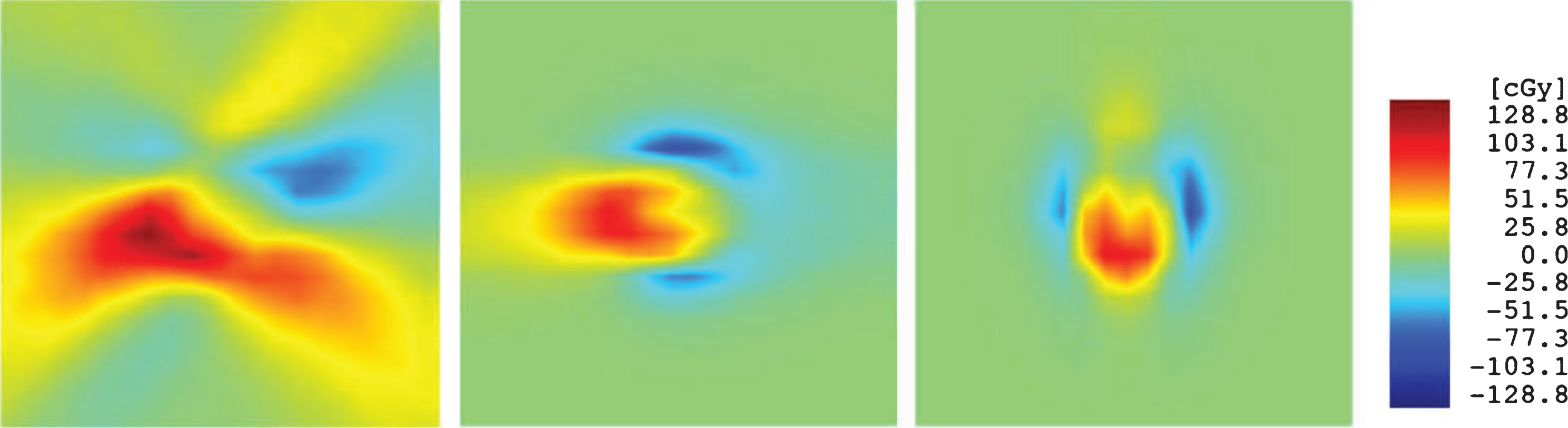
Comparison of dose distributions in a 14-cm sphere from two opposite circular arcs without and with beam axis shifts during gantry rotation. The three panels are dose differences in the axial, coronal, and sagittal views with 2 cm×2 cm dimensions. The global maximum dose is 25.14 Gy. The beam energy is 6 MV FFF and the cone size is 5 mm.
In the simulation plans where we treated the Lucy phantom with four non-coplanar circular arcs, the simulated residual patient setup error in either of the x, y, and z directions caused the volume of 70% isodose to shift in the opposite direction by the same amount of the assumed setup error. This result coincided with our intuition. From the results of table rotation simulations, it was interesting to note that for an assumed 0.5 mm table rotation radius, the volume of the 70% isodose only shifted by 0.1 mm from the volume without table rotation uncertainties. This shift was the same for all three cones, and was an order of magnitude smaller than that of the assumed table AOR radius. Table 3 lists the other dosimetric effects of table rotation uncertainties, most of which are negligible. Figure 5 displays the dosimetric effects of table rotation uncertainties for the 5 mm cone.
Estimated changes in the maximum point dose (Dmax) and Paddick’s gradient index (GI) of the 70% isodose volume with assumed 0.5 mm table rotation radius. Four 120° circular arcs of 5-mm, 10-mm, and 14-mm cones with table angles 40° apart deliver 1200 MU per arc using 6 MV FFF photon energy
Estimated changes in the maximum point dose (Dmax) and Paddick’s gradient index (GI) of the 70% isodose volume with assumed 0.5 mm table rotation radius. Four 120° circular arcs of 5-mm, 10-mm, and 14-mm cones with table angles 40° apart deliver 1200 MU per arc using 6 MV FFF photon energy
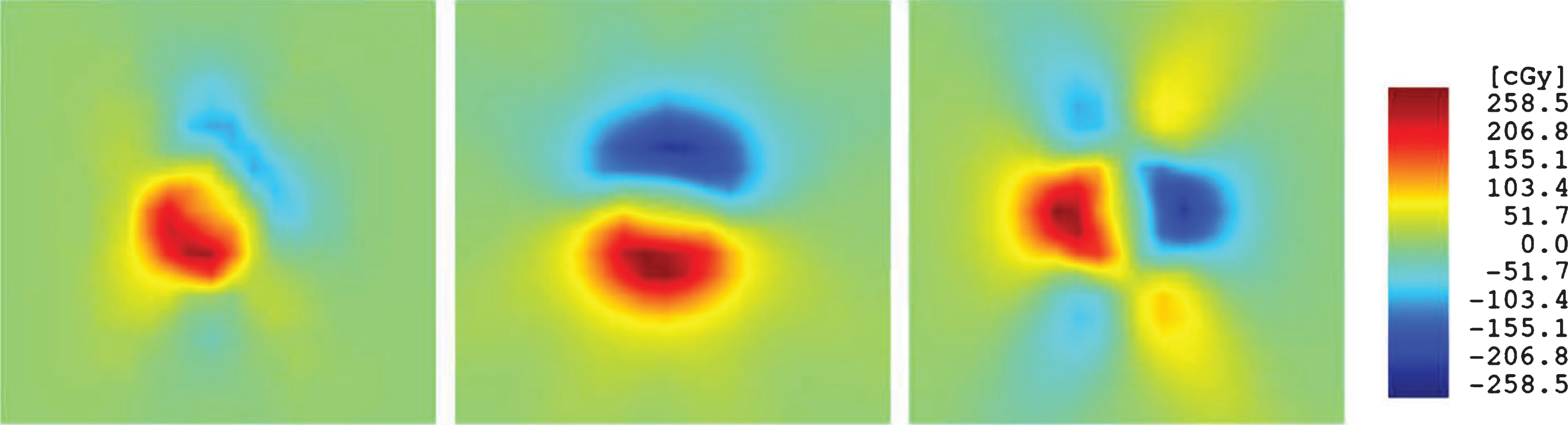
Comparison of dose distributions in a 14-cm sphere from four non-coplanar arcs without and with table rotation uncertainties. The three panels are dose differences in the axial, coronal, and sagittal views with 2 cm×2 cm dimensions. The global maximum dose is 50.49 Gy. The beam energy is 6 MV FFF, the cone size is 5 mm, and the table rotation uncertainties are 0.5 mm in radius.
Mechanical uncertainties are always a major concern regarding the delivery of linac-based SRS treatment [28, 29]. The American Association of Physicists in Medicine (AAPM) Report No. 54 [28] quantified five “achievable uncertainties in SRS” in its Table II, among which are isocentric alignment, CT image resolution, tissue motion, and angiography, which are still valid in contemporary non-invasive SRS procedures. We investigated the first two uncertainties in our end-to-end measurements. We performed these measurements using our own methods, which have achieved high levels of accuracy [20]. The mechanical baselines were established during the commissioning of this linac according to the AAPM TG-142 recommendations [29]. We must emphasize that the measurement data were specific to a single Versa HD linac, and they might not represent other machines.
Based on the results of a previous study [30] and our own measurements, we believe that the mechanical motions of modern linacs are relatively stable, thus thorough measurements of linac isocenters could be valid over a period of one year or so. The CBCT system, however, might be subject to a faster decline of mechanical accuracy and should be calibrated more frequently. Both Varian and Elekta linacs have imager mechanical calibration algorithms (IsoCal and Flexmap, respectively). It is prudent for the physicists to verify the discrepancy between the imaging center and the radiation isocenter for SRS linacs on a routine basis.
In the present study, we utilized a portal imaging based ball bearing phantom approach to determine the mechanical uncertainties in the Versa linac system. This method was initially developed with the intention to replace the conventional spoke shot that are subject to the MLC or jaw calibration uncertainties. Although this method is similar to the Winston-Lutz test, its results are not affected by the alignment of the ball bearing phantom. Because it is time consuming and requires specific software for analysis, we do not recommend using this method on a daily basis over of the Winston-Lutz test.
Although the Versa HD linacs exhibit larger mechanical variations during gantry rotation, these uncertainties only result in a mild “smear” of dose distribution for circular arcs compared to the ideal situation. In general, we see slight decreases in the maximum point dose and slight increases in the gradient index. The dosimetric changes are more notable for the smallest (5-mm) cone – the Gradient Index for the 5-mm cone increased because the radius of the 70% isodose volume reduced by 0.1 mm due to beam axis shifts. We expect that for MLC-based arcs, the impact of mechanical uncertainties is similar to that for the arcs based on larger cones, provided that the leaf position uncertainties are excluded. Therefore, when the uncertainties in CBCT guidance approach the 1 mm level, they will be a protruding factor.
In reality, the SRS planners must take all sources of uncertainties into account, including linac mechanical uncertainties and residual CBCT guidance errors. Currently, it is up to the attending radiation oncologist to determine the setup margin for a gross tumor volume while taking into account various uncertainties; however, a Versa HD-based SRS treatment program could develop an optimal setup margin. In the present study, we combined the high-precision mechanical measurements and dosimetric simulations to investigate the effects of the linac mechanical uncertainties. This method could construct the impacts of mechanical uncertainties on the dosimetric parameters and avoid the limitations of purely analytical setup margin estimates from measurement data. We hope that by doing so, researchers can derive more precise machine-specific and procedure-specific margins. Equipped with such knowledge, the SRS treatment team is able to determine the setup margins prior to any patient treatment on a given linac, and establish accuracy-based CBCT calibration guidelines.
It is interesting to note that SRS margin studies have been proceeding in two directions. First, researchers have attempted to determine a sufficiently large margin to address the uncertainties or errors in question. However, other researchers seek the smallest margin that can ensure sufficient target volume coverage. Radiation oncologists seek optimal dose delivery with less exposure to normal tissue. Such an approach has the potential to improve outcomes and toxicity profiles. Usually, dose gradient is not considered in the first approach, i.e., the beam profile is treated as a rectangular function. Such a treatment might result in an unnecessarily large margin. Therefore, we prefer the second approach in which the balance between target volume coverage and normal tissue sparing can be more readily achieved. Our results suggest that the required geometric margin to compensate for the mechanical uncertainties and residual CBCT guidance errors would be dominated by the latter. In this study, we used a p-value to indicate whether the phantom localization is dependent on the CT simulation or the initial phantom setup. Our results suggested that neither factor could significantly influence the phantom localization. This certainly removes one potential concern in the SRS procedures.
Typical SRS treatment fields are non-coplanar. For non-coplanar static fields, the extent of dosimetric consequences from setup errors should be dependent on the actual beam settings. These situations are difficult to analyze; however, for either coplanar or non-coplanar treatment field settings, the residual setup errors should translate into geometry target margins, although not necessarily in a 1 to 1 ratio [22]. In real life treatment plans, the “dosimetry margin” outside the target volume may provide a cushion within which the planners can take advantage. For regular SRS plans, the magnitude of dosimetry margin is often at the order of 1 mm around the target. Considering the dosimetry margin will avoid unnecessarily large geometry margins and excessive radiation doses to the normal tissues. This avoidance has the ability of enhancing the therapeutic ratio. In order to minimize the geometry margin in SRS treatment, the planners may utilize one-dimensional target expansions [30], if the average residual setup errors and associated standard deviations have been thoroughly measured.
Conclusions
Our results demonstrate that the accuracy of CBCT guidance will dominate the overall mechanical uncertainties in arc delivery on a Versa HD linac. This linac is an acceptable system for SRS treatment. We recommend that physicists evaluate the linac-specific mechanical uncertainties and CBCT image guidance accuracy in order to determine the safe setup margin for a treatment delivery modality.
Footnotes
Acknowledgments
The authors thank Kara Morgan and Ashley Simplot for their assistance in the CT scans and the CBCT guidance procedure. The authors thank Jeffrey Patterson, Grants and Scientific Writer/Editor at University of Nebraska Medical Center, for his editorial contribution.