
Abstract
OBJECTIVE:
Since in-house phantoms may provide effective quality control for gamma cameras in clinical settings, this study aims to assess an in-house phantom designed to perform quality control tests of a gamma camera using locally available, affordable materials. This is of particular importance in developing countries where scientific support may not be readily available.
MATERIALS AND METHODS:
The phantom was made from cylindrical plexiglass with a diameter of 230 mm and thickness of 60 mm. The phantom design was based on NEMA recommendations and only used materials that are locally available and generally accessible to most nuclear medicine departments and require minimal engineering instruction.
RESULTS:
The phantom demonstrated high levels of reliability and accuracy. The integral uniformity range was between 1.93% and 2.40%. The differential uniformity ranged between 1.48% and 1.70%.
CONCLUSION:
This work demonstrates that in-house phantoms are capable of monitoring gamma camera performance. This approach is particularly useful when scientific support is not easily accessible and when commercial phantoms are not readily available.
Introduction
Over the years, gamma cameras have conferred many benefits to nuclear medicine applications in the fields of diagnostics, radiotherapy, and have privileged the doctors for the examination of the patient as well. The availability of the radionuclide 99mTc and the evaluation of the gamma imaging technologies [1] have led to the timely development of the SPECT (Single-Photon Emission Computed Tomography) imaging technique [2–4]. This technique is based on the detection of radiation and the location of photons emitted by radioactive decay within the patient. To obtain this information, a regular evaluation of the performance for the imaging system is required. Maintaining and improving the health and well-being of patients is achieved by providing the best care, qualified personnel, and reliable diagnostic instruments, which directly and indirectly contribute to patient satisfaction. Consequently, the presence of a quality control phantom within a nuclear medicine imaging department ensures the quality of the instrument and the safe care of the patient [5]. Furthermore, achieving a high standard of effectiveness and reliability in the practice of nuclear medicine necessitates a suitable quality control program to sustain a defined level of safety and to avoid error over time [6, 7]. Ideally, this could be carried out by all qualified personnel: a medical physicist, technician or maintenance engineer (trained on the device by the manufacturer), laboratory technician, and physician [8–10].
In order to carry out a comprehensive quality control procedure, different geometrically shaped phantoms are needed - including bars, spheres, line-sourced, and point-sourced - that can either be purchased commercially or built in-house. These phantoms can be filled with radioactive solutions and used to detect subtle changes in a gamma camera’s performance prior to its clinical diagnostic use in order to avoid degradation in image quality [11–13]. Thus quality control procedures are important to maintain the quality of the provided diagnostic images. One of the most important parameters in need of daily testing is uniformity i.e., the ability of an imaging system to produce a uniform image when exposed to a homogeneous radioactive source. In general, this can be achieved either with a collimator (extrinsic) or without a collimator (intrinsic). As recommended by many international organizations (e.g., National Electrical Manufacturers Association (NEMA), International Atomic Energy Agency (IAEA)), similar to spatial resolution, the ability to display closely-spaced patterns of activity, image linearity and distortion, the ability to reproduce a straight line, should be confirmed six-monthly or at least annually, these can be performed either extrinsic or intrinsic[14–16].
NEMA (NEMA 2012) published a general approach to the routine quality control of gamma imaging systems before and after installation. It provides recommendations based on good clinical practices to support both the manufacturer and user communities [17, 18]. It describes how to carry out quality control procedures for a gamma camera with support and help from manufacturers. Often, all necessary phantoms can be conceptualized and realized in accordance with NEMA standards. Despite the availability of these standardized recommendations, practical implementation guidelines, and detailed instructions, it remains challenging for many nuclear medicine services to provide testing phantoms, which are required on a daily basis, due to the cost of materials or the lack of the required technology [19]. Moreover, phantoms utilized for quality assurance can be expensive and not always easily available and, as a consequence, quality control procedures cannot be performed [20]. The equipment can present inhomogeneity issues and may face problems related to maintenance and quality control for which additional scientific support is required. Ideally, the evaluation of gamma camera performance could be achieved using purpose-built phantoms that can be either purchased commercially or built in-house [21]. Therefore, there is a need for affordable phantoms that can be easily constructed and used during a routine basis if the quality control of SPECT systems is to be widely implemented [22, 23]. It is also of practical value to develop phantoms for routine testing using more accessible resources.
We hypothesize that an alternative in-house phantom can be used for routine quality control of a gamma camera. We also evaluated the phantom to establish its reliability by assessing the uniformity of the gamma camera. In addition, we compared the outcomes from the in-house phantom with those obtained from the point source of 99mTc, which are reflective of intrinsic uniformity. Nuclear medicine departments stand to benefit from this alternative and affordable way to make in-house phantoms suit their wishes and needs in accordance with the NEMA guidelines, descriptions, and recommendations. Hence, this work describes the design and conceptualized use of such a phantom.
Materials and methods
Phantom preparation and experimental methods
Phantoms are traditionally from plexiglass, a brand of acrylic PMMA (polymethyl methacrylate) material, which has many benefits and is available in a wide spectrum of colors and opacities. It can be molded into a variety of shapes including tubes, cylinders, large sheets, etc. and can also be machine manipulated and drilled. It is one of the most common and preferred materials for phantoms due to a few specific characteristics: highly transparent, highly impact-resistant, easy to clean and polish, highly durable, light, easy to transport, highly scratch and shatter-resistant. Furthermore, its density (1.17 to 1.20 g/cm3) is similar to humans and, as such, this material is bio-compatible. All these characteristics make it an ideal material to serve as a quality control tool to measure gamma camera performance [24–27].
The phantom was fabricated in-house. As seen in Fig. 1, it has a cylindrical shape with a diameter of 230 mm and thickness of 60 mm divided into two large sections (left and right). The right part consists of five series of cylindrical wells (A, B, C, D, and E). The diameters were different for each line of wells, 25 mm, 20 mm, 15 mm, 13 mm, 8 mm, 6 mm, and 4 mm, and these were drilled to different depths, 15 mm (A), 12 mm (B), 10 mm (C), 8 mm (D), and 7 mm (D), with a 4 mm distance between wells and an angular spacing between the sets of wells of 45°. The left part was divided into two series of bars (F and G), each 5 mm in diameter with exactly the same 6 mm depth but different lengths; the widths and the spaces between these were exactly 4 mm, with the bars drilled in two perpendicular parts (F and G). Figure 1 shows a photograph of the phantom, a pattern of its main form, and the cover (240 mm diameter and 10 mm thick).
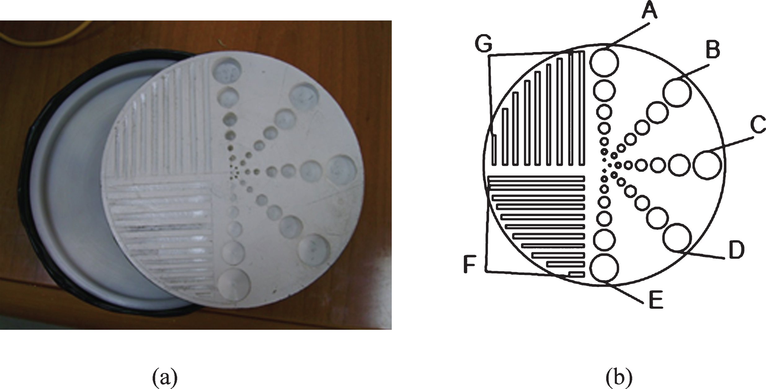
(a) a photograph of the phantom and its cover; (b) a schematic of the phantom’s shape.
This study was carried out in the Nuclear Medicine Unit of Gaziantep University Hospital using a double head detector SPECT gamma camera, model Forte With Jetstream, manufactured by Philips, as shown in Fig. 2. as shown in Fig. 2 [28, 29]. It was fitted with a low energy high resolution (LEHR) collimator, the thickness of the NaI crystal: 9.5 mm, size of the crystal: 508×381 mm, number of the photomultiplier tube: 49. The SPECT system was verified to ensure that the photo-peak was centered at the 140 KeV gamma line window of the radiotracer 99mTc widely used in diagnostic and detector had an energy solution of 15% at 140 KeV.

A photograph of the tested gamma imaging system.
Initially, a radioactive solution to fill the phantom was prepared. A sample of 99mTc was collected from the hospital’s generator on a daily basis. This was dissolved in a solution of sodium chloride (0.9% : physiological saline) and had an activity of 7.4×10⁻¹ GBq/ml, which was diluted with distilled water to 1.85×10⁻¹ GBq/ml 99mTc. The phantom was filled with radioactive material using a syringe, to control for air bubbles and ensure the homogeneity of the radiotracer. The acquisition was carried out with one head while the phantom was in the patient’s bed under the detector. The phantom was placed under the head to cover the region of interest in the field of view. The image was acquired with a 256×256×16 matrix size and the photo peak centered for 99mTc at 140 KeV with a 15% window, using a count mode of 250 million counts over 1200 seconds at a rate of 160 counts per second - static type. CFOV (Central Field of View) calculations were carried out to consider approximately 75% of the diameter of the detector. For each experiment, a sum of 10 million counts was used to assess integral uniformity. The same procedure was performed at various distances (5, 10, and 15 cm) between the phantom to the detector and at different times (i.e., three experiments conducted at two-month intervals). Uniformity was effectively assessed in the central 75% area of the homogeneous image. The uncertainties associated with the measurements were approximately 1.9%. The mean pixel values in the region of interest were calculated. Likewise, (IU and DU values) for the CFOV (Central Field of View) and UFOV (Useful Field of View) were calculated according to the method originally provided by the NEMA for quality assurance of nuclear medicine gamma cameras. The NEMA method uses maximum and minimum counts per pixel within the region of interest and average counts over nine neighborhood pixels. Subsequently, the count values measured in the nine adjacent pixels were considered to be the maximum and minimum counts observed in the CFOV [30, 31]. Lastly, the assessment of IU (integral uniformity) and DU (differential uniformity) indices for the UFOV and CFOV of the gamma camera can be calculated according to the NEMA, IAEA, and AAPM (American Association of Physicists in Medicine) guidelines, as expressed in Equations (1) and (2).
The phantom was placed in a horizontal position 5 cm from the detector and exposed for 15 minutes; the resulting image is presented in Fig. 3 (a). The upper left quarter of Fig. 3 (a) contains inhomogeneities that likely resulted from improper technique when filling the phantom with the radioactive solution. In the lower left quarter, this type of inhomogeneity is absent because proper technique filling was realized when filling the phantom. On the right-hand side of Fig. 3 (a), higher intensities were observed, which was expected since the activity contained within the wells is theoretically more important due to their volume. From experiment one, several conclusions can be drawn: The radioactive solution must be mixed well, and the phantom must be filled up carefully in order to avoid any radiotracer inhomogeneities. The phantom should be placed a good distance (at least 10 cm) away from the detector in order to avoid overlapping activities in the different wells and bars. The phantom should be placed horizontally and behind the camera head, in the extreme case of the entire phantom being moved 0.5 mm away at 5 cm, one would expect a change due to an r2 of ∼2%, which will affect the measurement.
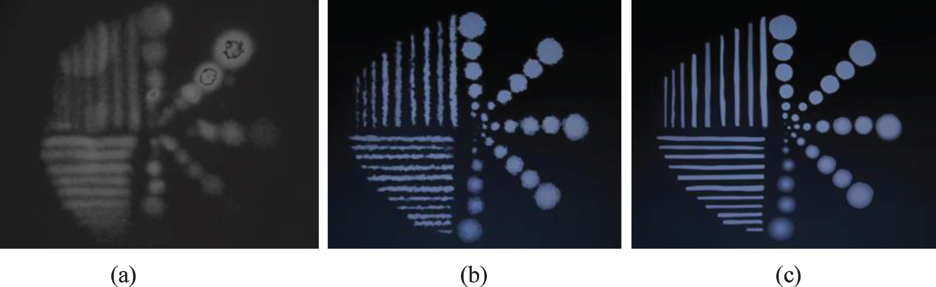
Gamma images show the phantom at different imaging distances: (a) 5 cm, (b) 10 cm and (c) 15 cm.
Given the findings from the first experiment, the phantom was emptied, cleaned, and not used for two months. At this point, it was filled with a well-mixed solution (agitated by vortex) of 99mTc 1.295×10⁻² GBq that was bubble-free and maintained 99mTc homogeneity. The phantom was placed about 10 cm from the detector, and the run time was set to 15 minutes. The obtained image can be seen in Fig. 3 (b) and has some discontinuities on the sides of the bars. These discontinuities are likely due to the effect of the surface tension on the walls, which indicates that filling the bars was poorly executed. Hence, this phenomenon was not observed at the wells level, especially those with large diameters. A slight radiological blur was also observed in this image, which could potentially be removed by placing the phantom away from the detector. As a result, the quality of the image improved relative to previous ones.
Experiment three
In this last experiment, a more homogeneous filling was performed, conforming to the same steps and conditions mentioned above were performed for filling up the phantom with 99mTc 1.295×10⁻² GBq. The phantom was placed to the detector at a distance of 15 cm. The results are presented in Fig. 3 (c), where images were evaluated in terms of uniformity, linearity, contrast, spatial resolution, and sharpness.
Intrinsic uniformity
In order to demonstrate the utility of this technique, another comparison of intrinsic uniformity test was performed. Intrinsic uniformity measurements were made using a point source of 99mTc to compare to those made by the in-house phantom. We initially followed the manufacturer’s instructions for the quality control test. Collimators were removed from the head. A point source of 99mTc with an activity of 1.295×10⁻² GBq was placed where the distance from the point source to the detector was at least four times the CFOV diameter. The image matrix size was 256×256, its energy window was adjusted to within 15%, and the count rate was 15 kcps (Kilo count per second). The gamma camera was equipped with software with which both the integral and differential values were automatically calculated using the formulas (1) and (2) [32–34]; these results are presented in Table 1.
Uniformity, mean, standard deviation, and constructor specification of the detector
Uniformity, mean, standard deviation, and constructor specification of the detector
Integral and differential uniformity of UFOV and CFOV obtained using a point source filled with 99mTc were compared with uniformity indices obtained from the corresponding constructor specification.
The outcomes described here provide an example of an affordable and technically useful phantom device and its application to extrinsic uniformity measurements in the routine quality control of a gamma camera using 99mTc.
The results presented in Fig. 3 (c) were used to assess the measured activity profile by scanning the series of wells (A). This profile was obtained using one of the applications installed in the gamma camera (Menu - Quality Assurance - Uniformity). For each well, the corresponding measured activity was extracted from the imaging data and recorded. Next, the real activities were plotted on the x-axis and measured activities on the y-axis in GBq and compared; a high level of correlation was observed between the two data series, as shown in Fig. 4. Thereby, using the least-squares method, a linear regression of these points was generated. There was indeed a significant positive association between the measured activity and the corresponding real activity with a slope of 0.8308x + 0.0045, correlation coefficient r = 0.99, and p < 0.01, which is consistent with a linear correlation with a high confidence level. Therefore, the resulting line was straight and well fit to the data. The error bars represent standard error estimates.

The relationship between the measured and real activities of the wells (A). Error bars represent standard error. The associated data points are connected by the line of the equation with a slope of unity and an intercept of zero.
Figure 5 (a) and (b) showing optimum values of the integral and differential uniformity at UFOV and CFOV have been obtained from different distances of 5, 10, and 15 cm (in-house phantom source-detector). The integral uniformity for CFOV was between 1.93% and 2.30% whilst the integral uniformity for UFOV was between 1.90% and 2.40%. The differential uniformity for CFOV was obtained between 1.48% and 1.60% whilst the differential uniformity for UFOV was between 1.55% and 1.70%. The integral uniformity range was found to be between 1.93% and 2.40% and differential uniformity has a range between 1.48% and 1.70%. In Fig. 5, both the IU and DU uniformity of UFOV and CFOV improved when phantom-to-camera distance augmented. The error bars in Fig. 5 (a) and (b) represent the standard error. The results shown in Table 1 give the IU and DU values for UFOV and CFOV using a point source of 99mTc. Calculated uniformity indices for the images acquired above by the in-house phantom were compared with uniformity indices obtained from the point source of 99mTc, the corresponding constructor specification, and the NEMA (Table 2). If the uniformity distortion is less than 3%, the quality is considered good and the corrections are activated. Alternatively, if the uniformity distortion is between 3% and 8%, it is necessary to calibrate the detector. If the uniformity distortion is greater than 8%, the calibration should be carried out by maintenance service. Moreover, for all measurements collected by the in-house phantom, the mean pixel values in the region of interest were recorded, with the mean integral uniformity values falling between 13 and 14.3%, which were within the acceptable range. Ten million counts were acquired for each image and these images had identical levels of associated uncertainty (1.9%).
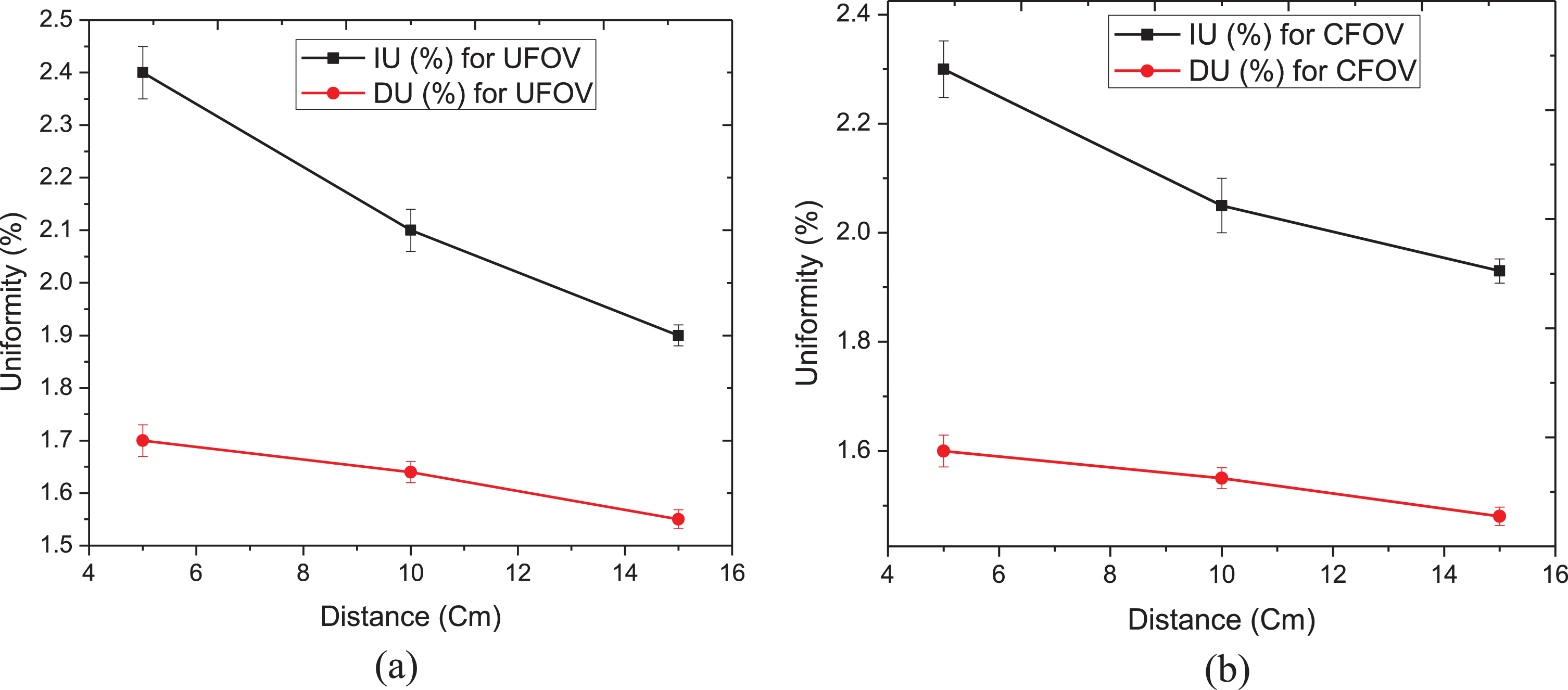
Integral and differential uniformity relative to phantom-to-camera distance for UFOV (a) and CFOV (b). The error bars indicate standard error. The uniformity values (integral or differential) improved with increasing phantom-to-detector distance.
The integral and differential uniformity values of UFOV and CFOV proposed by the NEMA
The integral and differential uniformity indices of UFOV and CFOV allowed by the National Electrical Manufacturer Association (NEMA).
Comparing the results obtained using the in-house phantom with the results of the point source of 99mTc indicated that the gamma camera’s uniformity was within an acceptable range. Thus, by evaluating the images acquired throughout this experimental work, it became clear that the quality of the scintigraphy images depends not only on the radioactive source, acquisition time, and sensitivity of the collimator, but also on the variation in the distance between the phantoms and the detector head.
The different depths and diameters of the wells lead to differential amounts of radioactivity contained in the volume of each well. Thus, from the images collected from these wells, the intensity differences within wells were considerably more distinguishable than between the bars. This facilitates the study of closely related contrast and spatial resolution: variations between wells enable the examination of the spatial resolution, integral uniformity, and differential uniformity of the detector. Moreover, the gamma camera reproduced, with a high degree of uniformity, images of the bars of the phantom with the radioactive solution. However, in this study, the spatial resolution parameter value was evaluated visually, because the detector could distinguish small details at 4 mm distance between the bars so even the smallest wells could be faithfully observed, as seen in Fig. 3 (c). This study focused on the determination of the uniformity aspect, as it is the most frequently utilized performance feature in the daily quality maintenance of gamma cameras. The results of the integral uniformity and differential uniformity analyses obtained using the in-house phantom and point source of 99mTc compared favorably with manufacturer and NEMA guidelines, which can be seen in Fig. 5 (a) and (b) and Tables 1 and 2. Therefore, the level of uniformity was within the recommended range and all measurement averages were within the acceptable limits. From our data, it shows that by increasing the source-to-detector distance either intrinsic or extrinsic uniformity improved (Fig. 5).
Despite the technical constraints encountered during the application of the in-house phantom and experimental work, our findings support that this phantom is, with some improvements, in accordance with the different calibration protocols for a gamma camera and can be easily incorporated into quality control procedures. This phantom is intended as a comprehensive quality control tool that is a simple and affordable solution for daily quality control when alternative phantoms are not available. In order to carry out the experiment, radioactivity levels between 1.85×10⁻² GBq and 2.96×10⁻² GBq should be used, similar to a radionuclide in clinical studies.
Moreover, using this tool, any nuclear medicine department can build or reformulate their own in-house protocol to assess the daily variation of uniformity parameters, which are suitable and acceptable. Although this phantom is well-suited; it was not intended to check each gamma camera performance. Rather, the objectives were to determine its unique capabilities and potential limitations in future studies. However, the phantom exhibited some differences from those that are designed or recommended by the manufacturer, NEMA, and user due to its geometrical form, however, the combination of wells and bars is, in fact, an advantage. Therefore, this system can evaluate the performance of a gamma camera in terms of uniformity, spatial resolution, energy, linearity, and contrast; even though these parameters are not all investigated during the experimental work, apart from the uniformity parameter. Future studies should include analyses of additional aspects of imaging such as spatial resolution, energy, linearity, and contrast.
Conclusion
The effectiveness of a scintillation camera quality control procedure is based on the system’s environment and its clinical use. The use of phantoms in nuclear medicine enables optimizing clinical protocols as well as validating correction methods and protecting patients against the consequences of false clinical examination results. The developed phantom represents a simple and affordable way to test a gamma camera’s performance. This may be applied, with acceptable accuracy, to the nuclear medicine field as quality control tests of a gamma camera. The level of the uniformity was within the acceptable range and all measurements were within acceptable averages. Furthermore, this work demonstrates that, using local and affordable materials that align with NEMA recommendations, in-house phantoms can execute daily performance tests of a gamma camera. Particularly in developing countries, scientific support is not always readily available. Therefore, we developed a novel technique to assess the uniformity of a gamma camera. The results indicated that this method was effective and offered a good uniformity when compared with the results obtained from the point source of 99mTc. Given the potential of this tool, future studies will include optimizing the spatial resolution, linearity, and energy resolution of a gamma camera in greater detail and at higher levels of accuracy.
Footnotes
Acknowledgments
Authors thank Prof. Dr. Y. Zeki Çelen, the head of nuclear medicine department and staff for their cooperation and help during this work.