



Abstract
Parabolic monocapillary X-ray lens (PMXRL) is an ideal optical device for constraining the point divergent X-ray beams to quasi-parallel beams, but the overlap of direct X-rays and reflected X-rays through PMXRL deteriorates the outgoing beam divergence. Aiming to solve this problem, this study designs and tests a square-shaped lead occluder (SSLO) embedded in PMXRL to block the direct X-rays passing through the PMXRL. Python simulations are employed to determine the geometric parameters of the SSLO as well as the optimal position of the SSLO in the PMXRL according to our proposed model. The PMXRL with a conic parameter p of 0.000939 mm and a length L of 60.8 mm is manufactured and the SSLO with a size of 0.472 mm×0.472 mm×3.4 mm is embedded into it. An optical path system based on this PMXRL is built to measure the divergence of the outgoing X-ray beam. The experimental results show that the quasi-parallel X-ray beam reaches a divergence of 0.36 mrad in the range from 15–45 mm at the PMXRL outlet. This divergence is 10 times lower than the theoretical divergence without SSLO. Our work provides an alternative method for obtaining highly parallel X-ray beam and is beneficial to generate or facilitate new applications of monocapillary optics in X-ray technology.
Introduction
X-ray optics has excellent capacity to regulate the beam direction, focal spot size, flux density and beam divergence, and the improvement of its performance continuously promotes the applications of X-ray in archaeology [1, 2], new energy [3, 4] and material science [5–7]. Quasi-parallel X-ray beams have a wide application prospect, especially in X-ray diffraction (XRD) [6–8] and X-ray imaging [9–13]. The divergence of quasi-parallel X-ray beams is an important factor limiting the application of X-ray technology. For example, the extremely low divergence is helpful to improve the spatial resolution of XRD systems, which makes it possible to observe the microstructural heterogeneities of nanocrystalline materials [12, 13]. For the measurement of residual stress by XRD [14], low divergence also reduces the effect of the original beam on the broadening of diffraction peaks. In addition, the signal-to-noise ratio of the small-angle X-ray scattering experiment [15] will improve with the decrease of beam divergence.
Consequently, it is important to obtain high-quality quasi-parallel X-ray microbeams in X-ray methodology. Considering that synchrotron radiation sources are not as accessible as common X-ray tubes [16], it is necessary to develop optical devices and methods to obtain quasi-parallel X-ray beams using X-ray tubes. At present, there are several ways to obtain quasi-parallel X-ray beams with X-ray tubes. V. V. Protopopov et al. designed an X-ray parabolic collimator with the technology of depth-graded multilayer mirrors and obtained a collimated beam with a divergence of 6.94 mrad at Cu k a radiation [17]. Tianxi Sun et al. designed a combined system of a polycapillary focusing X-ray lens and a cylindrical polycapillary collimator to obtain a micron-scale quasi-parallel beam [18]. Some researchers have reported that polycapillary parallel X-ray lenses can collect X-rays with large divergence and redirect them into a quasi-parallel beam [9, 19]. Although many collimation schemes have been developed, they provide only quasi-parallel beams on the order of milliradians. In contrast, a parabolic monocapillary X-ray lens (PMXRL) coupled with an X-ray tube can obtain almost no divergence beams in X-ray systems [20].
PMXRLs belong to the category of monocapillary optics, which are based on the total reflection of X-rays on the ultra-smooth glass surface to control the X-ray direction [21]. If the inner wall of PMXRL is smooth enough and perfectly conforms to the parabolic equation with a specific parameter, the light from PMXRL focus will parallel to the symmetry axis after being reflected by the inner wall, which can be simply proved by Fermat’s principle. Although PMXRL is an ideal optical device for obtaining quasi-parallel beams, it has few applications by now due to the challenges of evaluating the shape accuracy and blocking the direct X-rays through the PMXRL [22]. The shape accuracy of monocapillary optics is strictly required in the manufacturing process, which directly affects to the optical performance [19] of this device including the gain factor, beam size, transmission efficiency and beam divergence. Many recent studies [23–25] have focused on evaluating the shape accuracy of monocapillary optics (inner diameter error, center axis straightness, and profile curve error), while few works are concerned with efficiently blocking all direct X-rays passing through monocapillary optics. However, the overlap of direct X-rays passing straightly through the PMXRL and reflected X-rays also cause a large divergence of the outgoing X-ray beams [26].
In this work, a square beamstop (BS) is proposed for the first time to block direct X-rays, which can be embedded into the appropriate position of the PMXRL by relying on the support provided by its edges. The square BS is made of lead with purity of 99.9%, a commonly ionizing radiation shielding material, hereafter called square-shaped lead occluder (SSLO). Compared with placing a circular BS outside the monocapillary optics [22, 27], the implementation of SSLO avoids the support and adjustment provided by high precision multi-dimensional combined platform, thus is more conducive to the stability and miniaturization of the optical systems. A three-dimensional simulation model is presented to determine the size of SSLO and its exact location in PMXRL. Then, the Python simulations are performed using the above model to obtain the ideal outgoing X-ray spot at the outlet of PMXRL according to the beam tracing method. After manufacturing the PMXRL and the SSLO with specific parameters, an optical system based on the PMXRL coupled with the SSLO is built to test the divergence of the quasi-parallel beam of the PMXRL outlet. The experiment results exhibit the ability of our scheme to obtain extremely low divergence beam, which may contribute to X-ray microdiffraction analysis and the measurement of residual stress.
Design, fabrication and simulation of PMXRL
Methods
PMXRL is a reflective optical device based on the principle of total reflection, which is suitable for regulating X-rays with energy of less than 20 keV. It is well known that total reflection happens when the grazing angle θ of an X-ray is less than the critical angle of total reflection (θ
c
). The parameter θ
c
is related to the incident X-ray energy and the density of the glass material, as shown in the following equation [28]:
where ρ is the density of the glass (g/cm3) and E k is the incident X-ray energy (keV).
The transmission process of a divergent X-ray beam in the PMXRL and the ideal outgoing X-ray spot are shown in Fig. 1. The vertical distance from the coordinate zero point to the PMXRL inlet is D1 and the distance from the PMXRL outlet to the charge-coupled device (CCD) camera is D2. When an ideal point source emits X-rays from the focus of the PMXRL, only the X-rays within a specific range of solid angles enter the PMXRL. For the incident X-rays entering the PMXRL inlet, some of them directly leave the PMXRL without hitting the PMXRL inner wall, which are called direct X-rays, while the other reach the PMXRL inner surface with certain incidence angles. Only when the incident angles are less than θ c can the X-rays reaching the PMXRL inner surface leave the PMXRL along the z-axis direction after single-bounce, and they are named reflected X-rays. The position of PMXRL inner wall where the grazing angle of incident X-rays just satisfies the critical angle of total reflection is M1, and the position at the PMXRL outlet is M2. The X-rays reaching the region from M1 to M2 can be effectively reflected to form an outgoing parallel beam. If the direct X-rays can be completely blocked, an annular facula formed by a quasi-parallel beam can be obtain by CCD camera (see Fig. 1(b)). The projection on the Y-axis between M1 and M2 is the bandwidth of the annular facula.
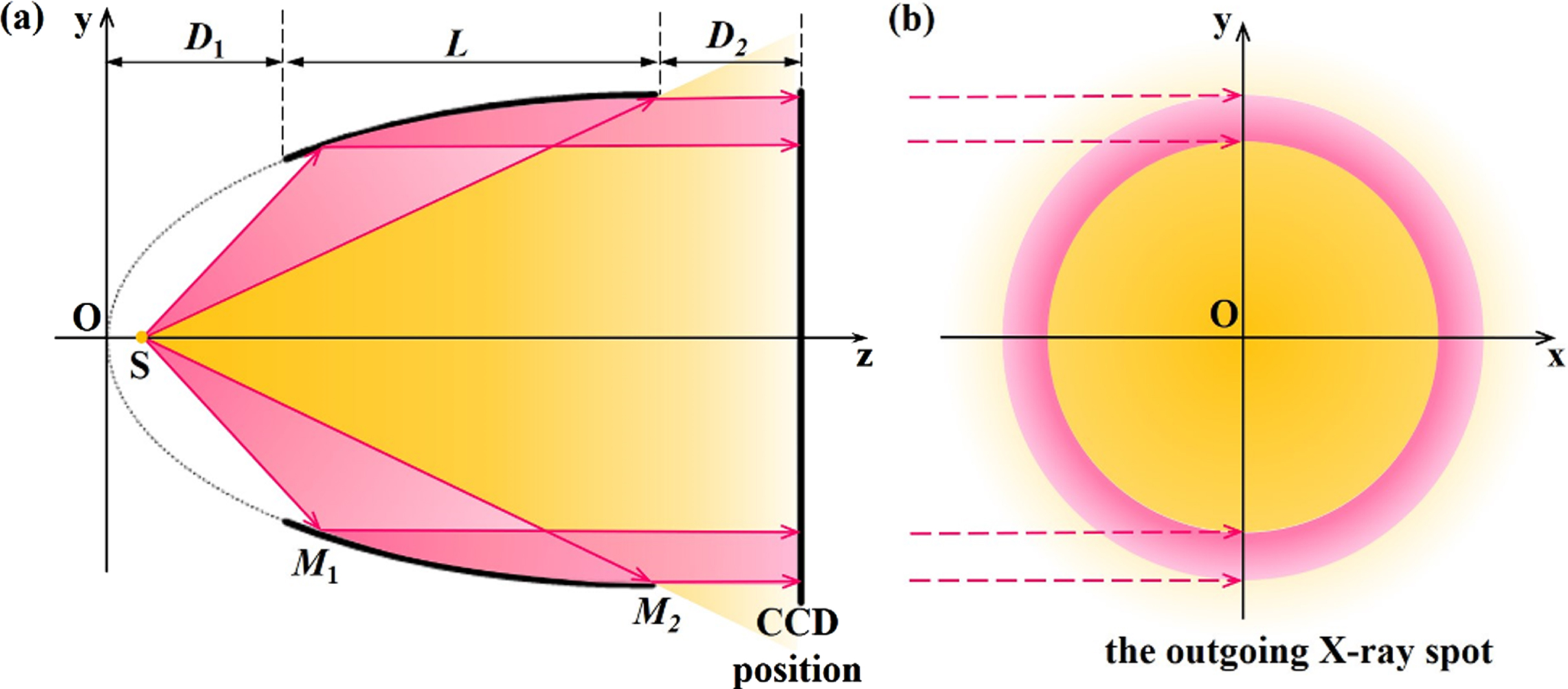
(color online) Schematic diagram of a PMXRL regulating X-rays. The orange areas represent direct X-rays and the pink areas are reflected X-rays. (a) The transmission of a point divergent X-ray beam in the PMXRL. (b) The ideal outgoing X-ray spot at D2 distance.
As shown in Fig. 2, a three-dimensional model of the PMXRL is established in O-zxy coordinate system to analyze the efficiency way of block direct X-rays, and the internal surface equation of the PMXRL is expressed as
(color online) Three-dimensional simulation model schematic of the PMXRL.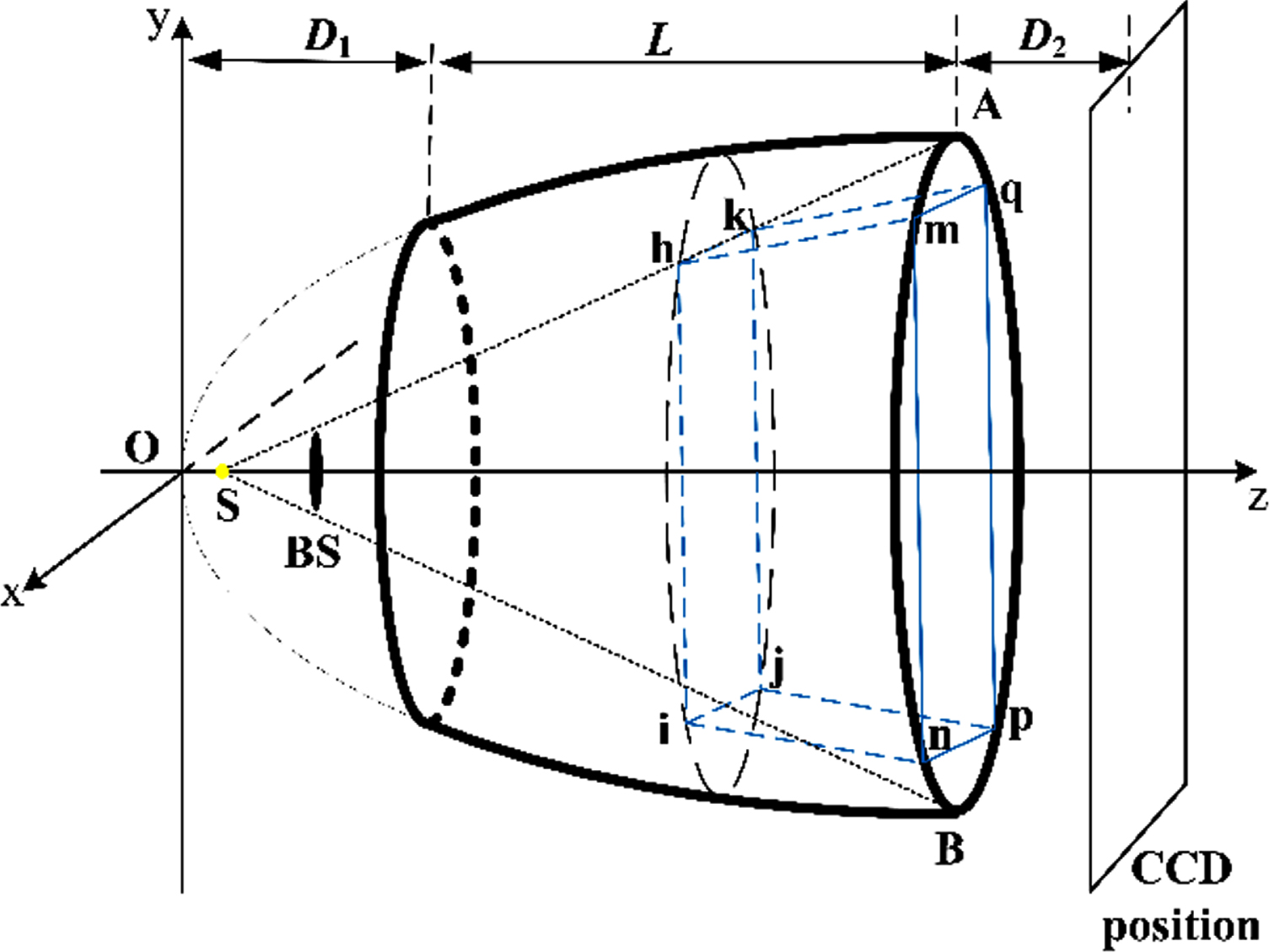
The X-rays emitted from source S within angle ASB in Fig. 2 are direct X-rays, which are usually blocked by a BS mounted on the optical path [22, 27]. A circular BS is obviously suitable to block all direct X-rays without sacrificing any reflected X-rays if only considering the geometric relation. However, circular BS needs additional support structures and multi-dimensional adjustment platforms [26] because it is usually placed outside monocapillary optics, which may greatly increase the experiment complexity. XOS, the world’s leading manufacturer of high-performance capillaries, proposed to embed a circular BS with three support structures at the outlet of the PMXRL [20]. Although the embedded design and integrated structure reduce the experiment complexity, processing the three supporting structures at sub-millimeter level is very challenging. To reduce the complexity, a SSLO is embedded in the PMXRL to block direct X-rays in this paper, using the square edge as the support. In the three-dimensional model of the PMXRL shown in Fig. 2, the eight vertices of the SSLO are represented by letters h, i, j, k, m, n, p, q.
A simulation model (Fig. 3) is built to determine the optimal location of the SSLO in the PMXRL. To simplify the simulation, the plane hijk in Fig. 2 is used to represent the optimal position of the SSLO in the simulation program. That is to say, the thickness of the SSLO is ignored in all simulations of this work. In Fig. 3, the circular BS2 represents the area of all direct X-rays at the plane hijk. Similarly, the circular BS1 represents the area of all direct X-rays at the plane h’i’j’k’. The SSLO size varies with the position where it is embedded. Its final size should be determined by the optimal position where it just blocks all direct X-rays. The square hijk in Fig. 3 is exactly tangent to the circular BS2, meaning that the SSLO placed at the plane hijk can cover all direct X-rays and minimize the loss of reflected X-rays. When the position of the SSLO is in front of plane hijk, such as plane h’i’j’k’, a larger percentage of the reflected X-rays are lost because the side length of the embedded SSLO is larger than the diameter of the circular BS1. When the position of the SSLO is located behind plane hijk, the situation is just the opposite, and the direct X-rays cannot be completely blocked.
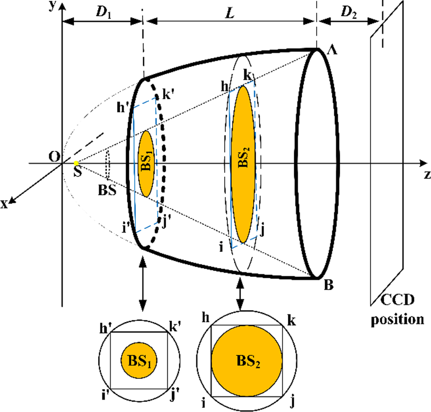
(color online) Simulation model schematic of the PMXRL with the SSLO.
In addition, the fraction of reflected X-rays blocked by SSLO when it is at the optimal position is calculated by analyzing the above geometric relationship. The result shows that the areas of BS2 and the square hijk account for 50% and 63.66% of the cross-sectional area of the PMXRL at the optimal position, respectively. This scheme sacrifices 13.66% of the reflected X-rays without considering the intensity distribution of X-rays at the plane hijk.
Monocapillary optics are usually fabricated from hollow cylindrical borosilicate glass tubes with a density of 2.2∼2.4 g/cm3 by a pulling system [29]. In this paper, a glass tube with an outer diameter of 20.5 mm and an inner diameter of 2 mm is selected to fabricate the PMXRL. After processing the glass tube by a pulling system, we need to determine the optimal boundary range of this processed tube and cut it. In our previous work, a source code package named “PSO X-ray Finder” was developed to find the optimal boundary range of monocapillary optics [30]. The implementation of this method needs to obtain the inner surface contour data of the processed tube. It is usually assumed that the ratio of inner to outer diameters of the hollow cylindrical borosilicate glass tubes remains constant after being processed by the pulling system [31]. Based on this assumption, we scanned the outer surface contour of the processed tube and converted it to an inner surface contour, as shown by the blue line in Fig. 4(a). With the “PSO X-ray Finder”, the inner surface contour data are processed to obtain the region satisfying the parabolic equation (y + a)2 = 2p(x + b) (see the red line in Fig. 4(a)), and the results show that the parameter p is 0.000939 mm. Figure 4(b) presents a partially enlarged view of Fig. 4(a), showing the two boundaries of the processed tube conforming to the parabolic equation. If shifting the vertex of the parabolic to the origin of the coordinate (see Fig. 1), the inlet end of the PMXRL is located at z = 58.4 mm, and the outlet end of the PMXRL is located at z = 119.2 mm. Therefore, we cut the processed tube according to Fig. 4(b) and obtain the PMXRL with a length L of 60.8 mm.

(color online) (a) The inner surface contour of the processed tube by the pulling system (the blue line shows the full tube outline, and the red line shows the standard parabolic equation fit result). (b) The region to be cut of the processed tube. (c) Photograph of the PMXRL corresponding to subfigure (b).
After obtaining the PMXRL parameters, we develop a Python program based on the simulation model (Fig. 3) to find the optimal position of the SSLO using the method described in Section 2.1. The simulation results show that the optimal position of the SSLO is 59.6 mm, and the size of the SSLO is 0.472 mm×0.472 mm. Considering that the beam divergence at PMXRL outlet will be measured with a Cu target X-ray tube in this study, the thickness of the SSLO shall ensure that Cu k a X-rays are completely absorbed, which can be calculated using the Beer-Lambert law. Since suitable thickness is needed to ensure that the edges of the SSLO provide support, the manufactured thickness is greater than the theoretical calculation value. Thus, an SSLO with a size of 0.472 mm×0.472 mm×3.4 mm is made and embedded into the PMXRL from the large diameter end of the PMXRL. In addition, the surface of SSLO is finely polished to reduce diffraction.
In the following a Python simulation program based on the simulation model (Fig. 3) are performed to simulate the ideal outgoing X-ray spots after the PMXRL outlet by using the ray-tracing algorithm [32, 33]. In this program, the parameters in the simulation model —including the length L and conic parameter p of PMXRL, the size and optimal position of the SSLO, the distance D1 between PMXRL and the source spot —can be find in Section 2.2. Besides that, the diameter of the X-ray source spot is 8μm and the energy of X-rays is 8 keV in the simulation. The ray-tracing algorithm needs to judge whether X-rays are reflected or absorbed according to the critical angle of total reflection θ c , which is calculated as 3.79 mrad according to Eq. 1. Considering the complexity of the computation, the attenuation of X-rays in the air, the X-ray diffraction at the corners of SSLO, and the shape error and roughness of PMXRL are ignored in the simulation.
Here, 1×10⁶ events are simulated to obtain the outgoing X-ray spot (Fig. 5) at the PMXRL outlet plane (the distance D2 between PMXRL and the CCD camera is set to zero). The outgoing X-ray spots are not annular because the SSLO is used instead of a round BS. This outgoing X-ray spot has a circular inner contour and is composed of four crescent shaped spots connected successively. Another characteristic of the outgoing X-ray spot is centrosymmetry, which is consistent with the symmetry of the PMXRL and the SSLO. Our simulation data show that this spot consists only of reflected X-rays, meaning that all direct X-rays are blocked. Simultaneously, these simulation data show that the transmission efficiency (the ratio of the number of reflected photons to the total number of events) is 37.6%. The simulations of the outgoing X-ray spots (not shown here) at different parameters D2 are also performed, and the results are agreed well with Fig. 5, indicating that the X-ray beam at the PMXRL outlet is parallel under ideal conditions.
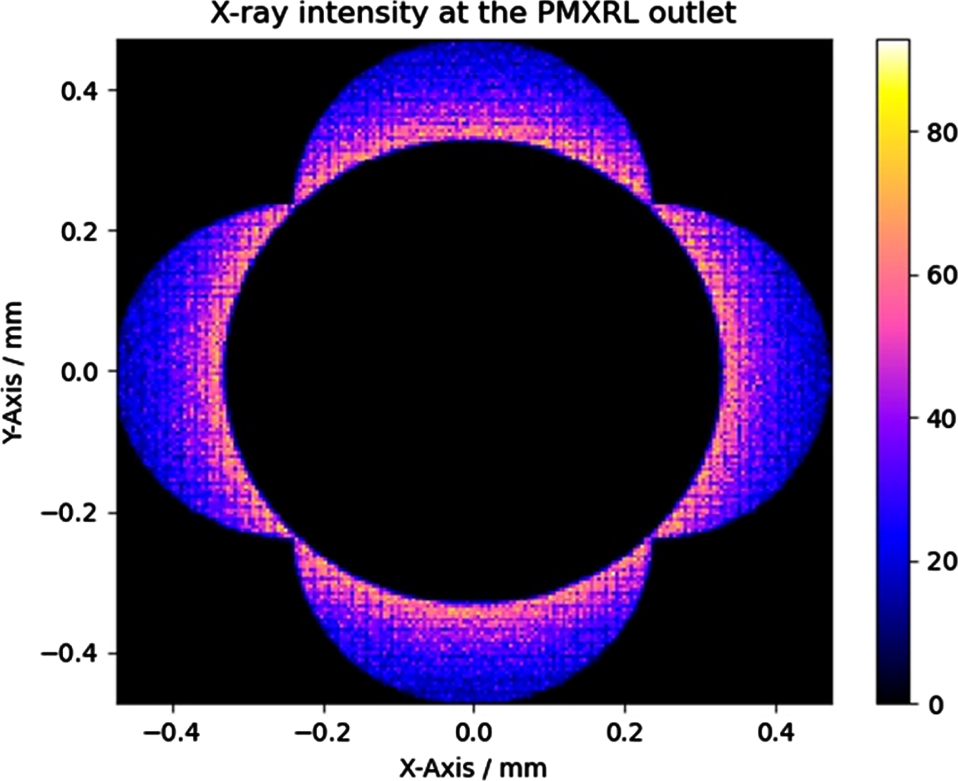
(color online) Simulated outgoing X-ray spot at the PMXRL outlet. The color index represents X-ray intensity.
It should be noted that the shape of X-ray spots shown in Fig. 5 only represents the result corresponding to PMXRL under specific parameters. The shape of the outgoing beam spot considerably depends on the parameters of the PMXRL, such as the coordinate of PMXRL inlet, the coordinate of PMXRL outlet and the parameter p. For example, when the coordinate of PMXRL inlet is changed from 58.4 mm to 40 mm, the simulated outgoing X-ray spot shown in Fig. 6 is completely different from Fig. 5. The spot in Fig. 6 is comprised of just 1×10⁵ events, yet this is sufficient to clearly show the spot shape.

(color online) Simulated outgoing X-ray spot at the PMXRL exit (D2 = 0 mm) when the coordinate of PMXRL inlet is changed to 40 mm.
An optical path system (Fig. 7) consisting of a Cu target X-ray tube [TFX-8100, Trufocus, USA], a CCD camera [M11427-61, Hamamatsu, Japan] and the PMXRL coupled with SSLO is built to measure the beam divergence after the PMXRL outlet. The schematic diagram and photograph of the optical path system are shown in Fig. 7(a) and Fig. 7(b) respectively. The X-ray tube provides a divergence beam with a solid angle of 48 degrees and its source spot with a diameter of 8μm is located at the focus position of the PMXRL to ensure that the reflected X-rays are parallel to the symmetry axis of the PMXRL. The operating parameters of the Cu target X-ray tube are set to 28 kV and 0.14 mA. The outgoing X-ray spots (Fig. 8) are measured at different D2 distances (15–45 mm), and the exposure time of each group is 10 s.
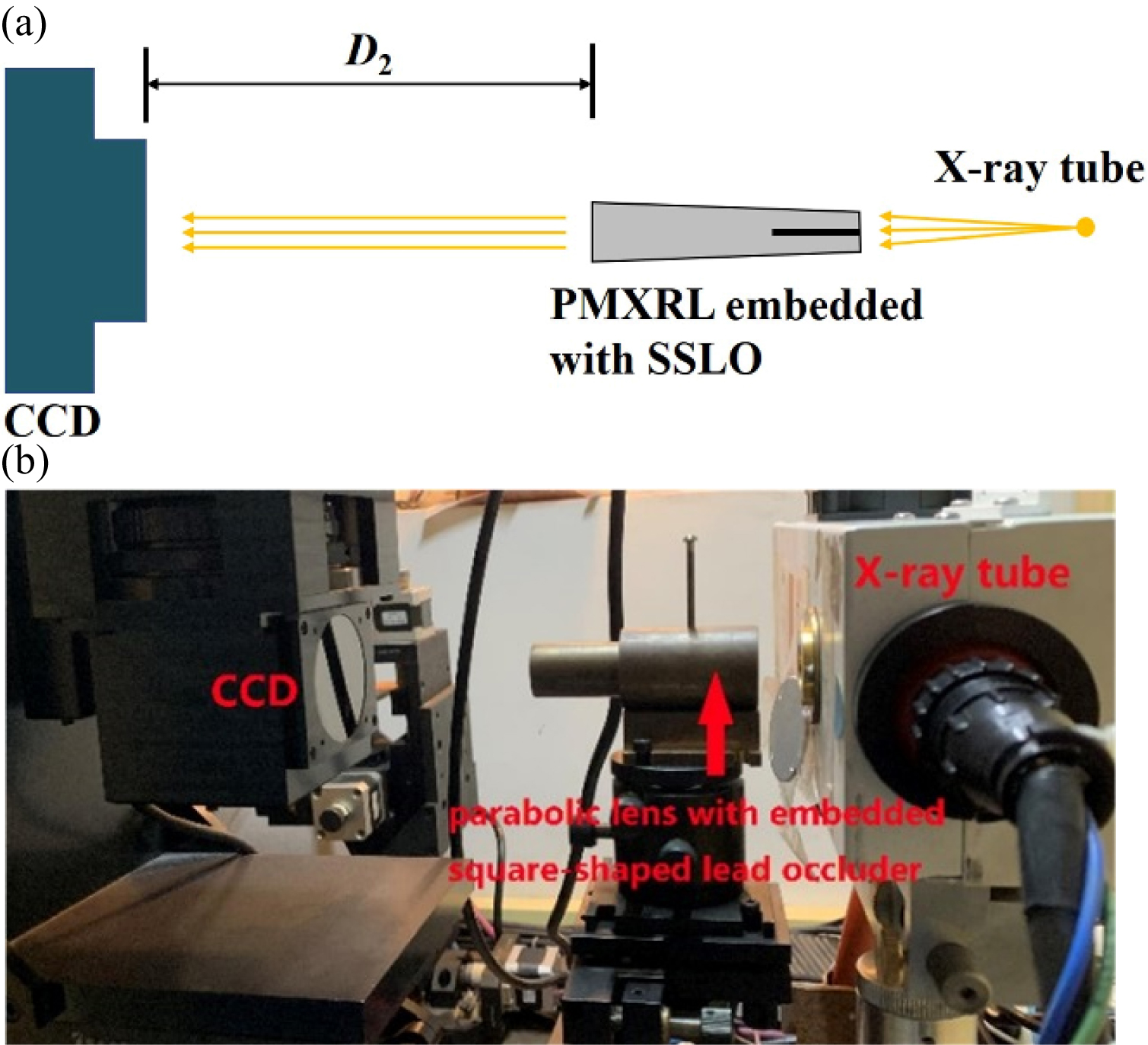
(color online) (a) Schematic diagram of the experimental arrangement. (b) Photograph of the experimental setup.
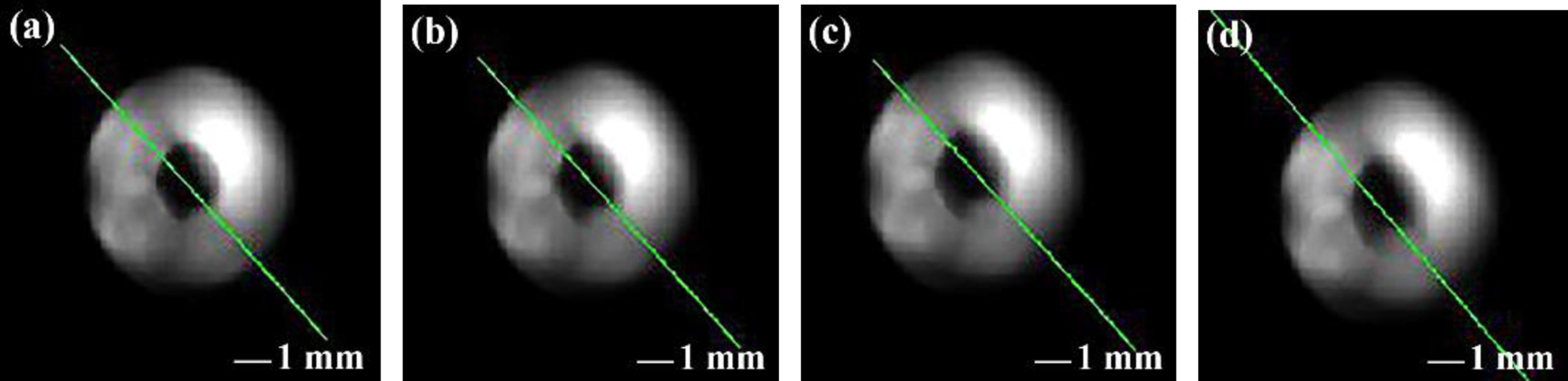
(color online) Outgoing X-ray spot photographs at different D2 distances: (a) D2 = 15 mm; (b) D2 = 25 mm; (c) D2 = 35 mm; (d) D2 = 45 mm.
The full widths of the outgoing X-ray spots are measured to evaluate the divergence of the outgoing X-ray beam because the outgoing X-ray spots are not normally Gaussian distributed. For example, to obtain the full width of the outgoing X-ray spot at D2 = 35 mm (Fig. 8(c)), the count profile data are generated by drawing a green line profile with the CCD camera software, thereby producing the X-ray intensity distribution (Fig. 9) along this green line profile. As shown in the inset of Fig. 9, the positive orientation of the green line profile is consistent with the horizontal axis direction of Fig. 9. Since the origin data and the smoothed data are highly consistent, only the smoothed data are shown in Fig. 9. The red profile is the 9-point Savitzky-Golay smoothed result of the line profile, and the corresponding polynomial order is set to 3. The criteria for selecting this set of parameters are maintaining the shape of the original data profile and minimizing fluctuations. The two peaks of the red profile are named the left peak and the right peak, while the blue curve that is the 1st derivative of the red profile determines the real spot size by identifying its extreme points. The left peak extends from the 180μm pixel channel to the 550μm pixel channel and the right peak extends from the 900μm pixel channel to the 1210μm pixel channel (see Fig. 9); therefore, the widths of the left peak and the right peak are 370 mm and 310 mm respectively and the full width of the outgoing X-ray spot is 1040 mm. All the results (Table 1) of different D2 positions can be obtained by taking the above steps. Further, we determine the outgoing X-ray beam divergence with the data of the left peaks. The black dots in Fig. 10 show the left peak widths of the X-ray spots at different D2 distances, and the red line is the linear fitting result. The 95% confidence band is confirmed during the fitting process, and the divergence is confirmed to be 0.36 mrad.

(color online) Savitzky-Golay smoothing curve of the green profile in the X-ray spot photograph at D2 = 35 mm (red line) and its 1st derivative curve (blue line). In the inset, the X-ray spot shown in Fig. 8(c) is rotated counterclockwise by 47 degrees.
The widths of the X-ray spots at different D2 distances

(color online) The beam divergence determined by the spots at different D2 distances.
We also calculate the gain factor of the PMXRL, which refers to the power density amplification of the PMXRL. The PMXRL inlet is 58.4 mm away from the X-ray source spot with an energy of 8.04 keV, and the PMXRL outlet is 20 mm away from the CCD. The PMXRL inlet diameter is 0.67 mm, and the outlet diameter is 0.95 mm. When the PMXRL is located on the optical path, the diameter of the outgoing X-ray spot is 1.04 mm, and the spot intensity is 0.41 times that of the spot intensity at the PMXRL inlet. When there is no PMXRL on the optical path, the diameter of the outgoing X-ray spot is 1.55 mm, and the spot intensity is 0.18 times that of the spot intensity at the PMXRL inlet. The gain factor of the PMXRL is calculated as 2∼3 based on the above results.
In this work, a PMXRL embedded with an SSLO is developed to convert point divergence X-rays to quasi-parallel beams. A quasi-parallel beam of 0.36 mrad is obtained by using an optical system composed of a PMXRL and a Cu target X-ray tube. According to Fig. 1, the beam divergence of the PMXRL outlet without the SSLO is theoretically calculated to be 3.87 mrad, which implies that the beam divergence is reduced by approximately 10 times with the use of an SSLO. The divergence of the X-ray beam provided by our scheme is comparable to that provided by the synchrotron radiation source [34, 35], indicating that our scheme can provide a high-quality quasi-parallel beam. Furthermore, the comparison (Table 2) between the three reported schemes [18, 37] for obtaining quasi-parallel beams and our scheme shows that our scheme can provide quasi-parallel beams with very low divergence but very poor gain. Therefore, the scheme present in this work needs to combine an ultra-bright X-ray tube to meet the requirements of specific X-ray analysis. In addition, the large working distance is a unique advantage of the PMXRL.
The characteristics of different collimators at Cu k
a
radiation
The characteristics of different collimators at Cu k a radiation
In the future, an aperture of submicron size can be added at the PMXRL outlet to obtain a focal spot with a diameter of 50∼1000 nm for microscale X-ray diffraction analysis. We believe that this scheme will contribute to the development of X-ray analysis technology, especially XRD technology, and the proposed method provides a new approach for the research of the BS devices used in monocapillary optics. For example, an X-ray diffractometer with parallel-beam optical system based on our work can be built, which has the capability of reducing the broadening of diffraction peaks caused by beam divergence, thereby more accurately measuring the microstructure and microscopic stress of materials.
Unfortunately, there are several differences between the experimental X-ray spots and simulated X-ray spots. The widths of the left peak and the right peak of the outgoing X-ray spots at different D2 distances are different (see Table 1), which indicates that the experimental X-ray spots in Fig. 8 are non-centrosymmetric. In addition to the difference of spot shape, the intensity distribution of the experimental X-ray spots does not show the same regularity as that of the simulated X-ray spots. The reasons for the above phenomenon are that the X-ray is polychromatic rather than monochromatic, the PMXRL has shape error and roughness, and there may be inaccuracy in the interception positions at both ends of the PMXRL. Moreover, some experiment limitations may also lead to this scenario, such as optical path misalignment and SSLO deformation.
Due to the possible misalignment and limited accuracy, we cannot guarantee that the source spot of the X-ray tube is at the focus of the PMXRL and the beam emitted by X-ray tube does not deviate from the central axis of PMXRL. Here, we simulate the outgoing X-ray spot (Fig. 11) when the X-ray source is defocused by 0.02 mm. That is, the coordinate of the X-ray source is set as (p / 2, 0.02, 0) in this simulation. The asymmetrical X-ray spot shown in Fig. 11 indicates that the misalignment between the PMXRL and the X-ray source is one of the causes for the different widths of the left and right peaks of the experimental X-ray spots. Similarly, the deformation of SSLO may lead to the error of its embedding position, affecting the accuracy of the experimental results. Future work will focus on the material selection and manufacturing of square BS, such as stainless steel, titanium alloy, ferronickel alloy, brass and other alloy materials with good hardness.
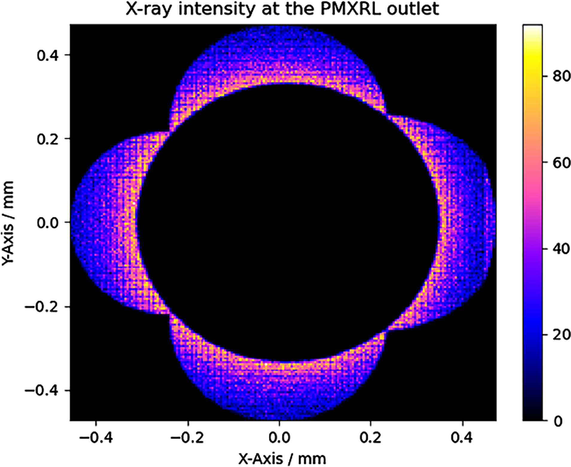
The simulated outgoing X-ray spot at the PMXRL outlet when the source spot of the X-ray tube is misaligned with the center axis of the PMXRL.
In this study, a PMXRL with a length of 60.8 mm and parameter p of 0.000939 mm is developed and an SSLO with a size of 0.472 mm×0.472 mm×3.4 mm is manufactured to embedded into this PMXRL. The measurement results show that the divergence of the outgoing X-ray beam is less than 0.4 mrad in the range from 15–45 mm at the PMXRL outlet, and it is 10 times lower than the theoretical divergence without the use of the SSLO. Therefore, a PMXRL with an embedded SSLO can obtain extremely low divergence X-ray beams and has a large working distance, offering the potential for practical applications in X-ray analysis methods. In the future research, we will build an X-ray beam analysis system according to this scheme and carry out related experiments by quasi-parallel beams.
Footnotes
Acknowledgments
This work was supported by the National Natural Science Foundation of China (Grant Nos. 11675019 and 11875087). The authors would like to acknowledge the American Journal Experts editorial team for editing this manuscript.