
Abstract
X-ray communication is a kind of space communication technology which uses X-ray as information carrier. In order to improve the information transmission capacity, communication rate and anti-interference ability of X-ray communication, we proposes to design a novel multi-target X-ray source. The source is composed of a fast switching module of light channels based on FPGA technology and four photoelectric X-ray tubes with different target materials: Cr, Fe, Ni, and Cu. Using Geant4 software, we determined the optimal target thickness for each material, which enabled us to fully leverage the characteristic X-rays for multi-channel signal modulation transmission. Moreover, using CST software for particle trajectory simulation and optimization of the electron beam revealed that at a tube voltage of 20 kV, the focus area measures approximately 1.2 mm×1.2 mm. The simulations show that four kinds of spectra with high distinctiveness can be generated from the Cr, Fe, Ni, and Cu targets. Within a single modulation period, these spectra can be combined in various ways to create 16 different X-ray spectra signals, thereby increasing the number of communication elements and enhancing the information transmission rate.
Introduction
X-ray communication (XCOM) technology is a communication method that uses X-rays for information transmission. XCOM was proposed by Dr. Gendreau in 2007 [1]. This technology has gained recognition for its large communication bandwidth, high confidentiality, small size, and low power consumption [2]. NASA has highlighted XCOM as a “revolutionary” concept in its space technology development plan [3].
The modulated X-ray tube plays a crucial role as a signal emission source in X-ray communication. The design of the X-ray tube and its electron generation and signal modulation modes significantly impact its structure and modulation speed. Research teams from different countries have proposed various design schemes for X-ray communication signal sources [4–9] and conducted extensive research in this field.
Currently, XCOM schemes primarily utilize intensity modulation/direct detection for signal modulation. The transmitter uses the presence or absence of full-energy spectrum X-ray photons to represent the “0” and “1” symbols, while the receiver uses the presence or absence of X-ray photons to recover the symbol information. However, in this modulation mode, the modulated X-ray source emits a wide energy spectrum, considering X-rays within a wide energy region as effective signals. In real space environments, such as those with high levels of background X-rays during solar activity, the presence of background X-rays can significantly interfere with signal discrimination at the detection terminal, leading to a degradation in communication performance.
Therefore, our team members proposed an X-ray signal modulation method based on energy load information. This method utilizes characteristic X-rays of different energies generated by electron bombardment of different targets as carriers of symbol information. The receiver can restore symbol information by detecting and recognizing the intensity of the characteristic X-rays of the corresponding energy [10]. This modulation method, when combined with a multi-target X-ray source, enhances the anti-interference ability of communication, increases the number of symbols, and has the potential to improve the information transmission rate.
Currently, research on multi-target X-ray sources primarily focuses on the application of X-ray fluorescence analysis. These sources are used to adjust the outgoing X-ray characteristic spectrum, enabling the accurate analysis of complex samples with multiple elements. Shuji Maeo’s team at the University of Electronic and Communications in Japan developed a three-target X-ray tube [11, 12] based on a mechanical transmission structure. This structure controls the swing of the anode target through an external mechanical transmission system. As a result, the electrons can bombard different targets without changing their flight trajectory, ultimately emitting different characteristic X-rays. However, the modulation mode of this mechanical transmission multi-target X-ray source does not meet the requirements of high-speed modulation.
In our previous work, we applied the electric field deflection electron beam method to an X-ray tube and developed a four-target transmission X-ray tube based on electric field modulation [13]. The beryllium window surface of the transmission anode was coated with four different targets at various positions. When the X-ray tube is operational, the electric field intensity distribution in the tube is altered by controlling the voltage of the four modulating electrodes within the tube. This change in the electric field allows electrons to be deflected and bombarded onto different targets, resulting in the emission of different characteristic X-rays. However, due to the power supply demand of the modulation electrode(on the order of 100 volts), the speed of modulation is restricted. Furthermore, as only one target can be bombarded at a time, the four-target transmission X-ray tube can only emit four kinds of X-ray spectra signals.
In addition, our team developed a dual-target X-ray tube [14–16] based on magnetic field modulation. The reflective anode base of the tube housed two different targets, while a ferromagnetic core coil placed outside the tube served as a magnetic field generator within the anode region. Controlling the power supply to the coil enabled the manipulation of the magnetic field in the tube. As a result, the electrons within the tube were deflected and bombarded onto the respective targets, thereby emitting two kinds of X-ray spectra signals.
Theoretically, by bombarding one or more targets in a modulation period, it is possible for n targets to emit up to 2 n kinds of X-ray spectra signals. One of the major advantages of the modulation method based on energy load information is the ability to utilize a large number of symbol elements. This necessitates an X-ray signal source capable of generating multiple characteristic X-rays while being able to freely combine them. As such, the study and design of a multi-target X-ray source that can achieve this freedom in combining characteristic emitted X-rays holds significant practical value. In response, our team designed a magnetic field-modulated four-target X-ray source by combining two double-target X-ray tubes and improving the magnetic field device. This X-ray source has the capability of emitting 16 different X-ray spectral signals. However, due to the adjacency of the targets, there is a risk of electrons inadvertently hitting nearby targets, resulting in characteristic X-ray noise.
To enhance the modulation speed of a multi-target X-ray source and reduce characteristic X-ray noise, the design of a four-tube four-target light modulated X-ray source (FFLMXRS) is proposed. The FFLMXRS consists of a fast switching module of light channels at the front end and four independent transmission photocathode X-ray tubes with the same structure at the back end. Each X-ray tube has different anode targets, with fixed target positions and directions of electron movement. The generation of electrons in each X-ray tube is controlled by modulating the light source signal of each photoelectric X-ray tube, resulting in the output of 16 kinds of X-ray spectra signals.
Signal source design and model building
Overall design
As depicted in Fig. 1, the FFLMXRS design primarily comprises an information-driven system and an optical signal-X-ray spectral signal conversion system. The information-driven system is responsible for transmitting modulation data from the upper computer to the FPGA module via the UART serial port. Subsequently, the FPGA module converts the modulation data into four parallel-level signals for output. Each of these four signal levels corresponds to one of the four light source channels. When the level is high, the corresponding light source channels are triggered to output optical signals. The four light source channels correspond to one of the four different target materials of the photoelectric X-ray tube. When the light source emits a signal, it drives the respective photoelectric cathode of the X-ray tube to generate electrons. These electrons then accelerate and collide with the corresponding target materials, producing modulated X-ray spectral signals. The modulated X-ray spectra signals are created by combining the characteristic X-ray spectra output from the four photoelectric X-ray tubes. This scheme utilizes the fast modulation of the light source and the quick response ability of the photocathode to achieve rapid modulation of the FFLMXRS. By driving the photocathode with the light source, the scheme ensures that electron generation occurs only when necessary, conserving the electric field energy. In contrast, in previous multi-target X-ray sources, electrons are continuously generated by the hot cathode upon starting, resulting in constant consumption of electric field energy. Although the proposed scheme offers a higher maximum output power, its energy utilization rate is also enhanced.

Schematic diagram of FFLMXRS scheme.
According to the modulation requirement of FFLMXRS, this paper selects the FPGA chip (Cyclone IV EP4CE10F17C8) to develop a fast switching module of light channels. This chip has the ability to support parallel output of level signals for multiple channels. The single-channel output frequency is adjustable and fast enough to provide a high-frequency light channel selection signal.
The Verilog HDL program is written in Quartus, and Fig. 2 shows the Register Transfer Level (RTL) view composed of the modules used. The modules, from left to right, include the serial port receiving module, RAM write control module, PLL clock module, RAM output control module, and RAM module. The input signals are the system clock, system reset signal, and serial communication signal, while the output is the four-way level control signal.

RTL view of fast switching module of light channels.
To verify the effectiveness of the program, the Pioneer EP4CE10 experimental platform was employed, and the embedded logic analyzer in Quartus was utilized to capture and display the signal in real time. The level channel data output frequency was set to 200 MHz, and a PC serial debugging assistant was used to send the UART serial hexadecimal modulation data “4e55414131355955414e41353038” to the FPGA. Upon completion of the data reception, as shown in Fig. 3, it can be observed in the embedded logic analyzer that the read enable signal ‘rden’ is pulled high, resulting in the output of the four drive level signals, and each modulation data output period is 5 ns. Consequently, the information drive system can achieve a modulation rate of 200 MHz.

Signal acquisition diagram of fast switching module of light channels.
When the light channels are selected, the corresponding light source stimulates the transmission photoelectric X-ray tube loaded with the corresponding target, resulting in the production of characteristic X-rays. Figure 4 depicts the main structure of a single transmission type photoelectric X-ray tube, with the optical quartz glass input window located on the left end face and the transmitted photocathode positioned inside the input window. The photoelectric X-ray tube utilizes S20 as its photocathode material due to its mature preparation process, stable operation, and high quantum efficiency [17].

Structure diagram of transmission type photoelectric X-ray tube.
The copper welding ring connects one side to the anode cylinder and the other side to the beryllium window. To enhance heat dissipation, TUI copper is used to construct the anode cylinder and the target welding ring. The anode shielding ring and cathode are produced from Kovar alloy. To maintain vacuum and electrically isolate each electrode, Al2O3 ceramic tubes were brazed between the cathode cylinder and the anode shielding ring. The target assembly is composed of an anode tube, a copper welding ring, a target, and a beryllium window.
An electron beam motion simulation model for the photoelectric X-ray tube was established using the particle studio of the electromagnetic analysis software CST, as illustrated in Fig. 5. The model has a maximum diameter of 40 mm, with the photocathode located on the card slot of the cathode, represented as a thin sheet without thickness. The properties of the material were set to photoemission, with the photoemission parameters set according to the performance of the S20 photocathode (shown in Table 1). Although the S20 photocathode is a nonmetallic material, its photoelectrons are emitted from the inside of metal atoms, so it can simulate the electron emission effect of photons excited at specific wavelengths. The cathode cylinder, anode shielding ring, photocathode, and beryllium window are defined as PEC materials (perfect electrical conductors) in the simulation, while the anode cylinder, target welding ring, and target are defined as copper materials. All other materials are defined as vacuum. The cathode is grounded, while the anode maintains a positive high voltage of 20 kV.

Photoelectric X-ray tube model in CST.
Simulation parameter Settings
X-ray photons in the low energy range of 1 to 10 KeV are easily collected by X-ray collimating optics and X-ray focusing optics [18]. We also consider that the K-series characteristic X-ray emission intensity is high, and the energy of a single photon is high enough to pass through the beryllium window at a small attenuation rate. Moreover, the energy intervals of each characteristic X-ray photon are clearly distinguished. Four targets, Cr, Fe, Ni, and Cu, with a large number of emitted characteristic photons and different characteristic energy, were selected in this range.
The characteristic X-ray parameters of the targets are provided in Table 2.
Characteristic energy of target elements
Characteristic energy of target elements
In transmission-type X-ray tubes, the thickness of the target material significantly affects the emission spectrum [19]. On the one hand, increasing the thickness of the target material increases the intensity of the produced X-rays. On the other hand, the attenuation of the X-rays becomes higher as the thickness of the target material increases. If the target material is too thin or too thick, fewer or no X-rays may be emitted. Therefore, each target material has an optimal thickness for determining the incident electron energy. We define the optimal thickness as the thickness of the target material with the highest characteristic X-ray intensity in the emission spectrum, which differs from the definition of many scholars who define the optimal thickness as the thickness that maximizes the total emission X-ray intensity.
To determine the best thickness of different targets and evaluate the emission effect of X-ray spectra, a simplified model of the anode target assembly was created in Geant4 software (Fig. 6). X-ray spectrum emission simulations were then conducted. The kinetic energy of the electrons was set at 20 keV, and the electron beam was directed to bombard the target material. The beryllium window thickness was 300μm, and the target material was coated on the surface of the beryllium window. A detector was placed outside the beryllium window to record the emitted photons. For each simulated electron bombardment, 2×10⁸ electrons were emitted to ensure a relative error of less than 1% in the statistical data.

Anode target assembly model in Geant4.
When electrons bombard the target, approximately 99% of the energy is converted into heat. In a transmission photoelectric X-ray tube, if the input heat load is too high, the target material plated on the beryllium window may detach or evaporate. Therefore, it is essential to conduct thermal load simulation analysis on the anode target assembly of the designed photoelectric X-ray tube to ensure safe operation. This paper utilizes the transient thermodynamic analysis module of the finite element analysis software ANSYS Workbench to simulate the heat transfer capacity of the anode target assembly.
The anode target assembly consists of an anode tube, a target welding ring, a beryllium window, and a target. The beryllium window has a thickness of 300μm, and for the simulation, the target material used is an iron (Fe) target with the lowest thermal conductivity and a thickness of 3.4μm. Table 3 presents some thermodynamic parameters of the target materials, which are assumed to be constant despite their temperature-dependent properties, as they have minimal effects on the final results.
Thermodynamic parameters of the target
Thermodynamic parameters of the target
The target module model and heat transfer parameters in ANSYS are depicted in Fig. 7. The ambient temperature is set to 22°C, and the convective heat transfer coefficient is set to 25 W/(m2·K) in area A of the target module (exit end face and side face). Heat radiation is provided in area B (all surfaces) of the anode target assembly, with a thermal power input of 20 W set at the focal imprint at area C of the transmission target (simulating the operation of the ray tube at a tube voltage of 20 kV and a tube current of 1 mA).

Target component model in ANSYS.
Beam dynamics
The initial model established in CST is presented in Fig. 5, with the particle emission source set on the surface of the light model. The grid was manually encrypted at the photocathode, with an absolute step size of 0.4 mm in the x and y directions and 0.5 mm in the z direction. Ultimately, approximately 1.24 million hexahedral grid units were divided. The boundary conditions are set to open. When using a trace solver, the relative error is set to less than –20 dB. To maximize the number of electrons reaching the anode target and achieve a good focusing effect, the key dimensions of the internal structure of the ray tube were obtained through parameter scanning and automatic optimization in CST, as shown in Table 4. The resulting particle flight trajectory is shown in Fig. 8.

Particle flight trajectory diagram. (a) Photon emission trajectory (b) Electron emission trajectory.
Key dimensions of internal structure of photoelectric X-ray tube
In Fig. 9, the electron beam target location and density information reveal that the central charge density is above 0.002 C/m3, the focal spot size is approximately 1.2 mm×1.2 mm, and the electron arrival rate is 90.4%.

electron beam target position and density information. (a) Electron distribution (b)Charge density distribution diagram(C/m3).
Figure 10 illustrates that the number of electrons arriving at the target quickly peaks at the start of target shooting and gradually decreases over time. Taking the average of all electron transit times as the electron transit time, the electron transit time of the photoelectric X-ray tube is 1.85 ns. Taking the time span from the beginning of electrons to the basic arrival of all electrons at the target as the electron transit dispersion time, the electron transit dispersion of the photoelectric X-ray tube is approximately 1.99 ns.
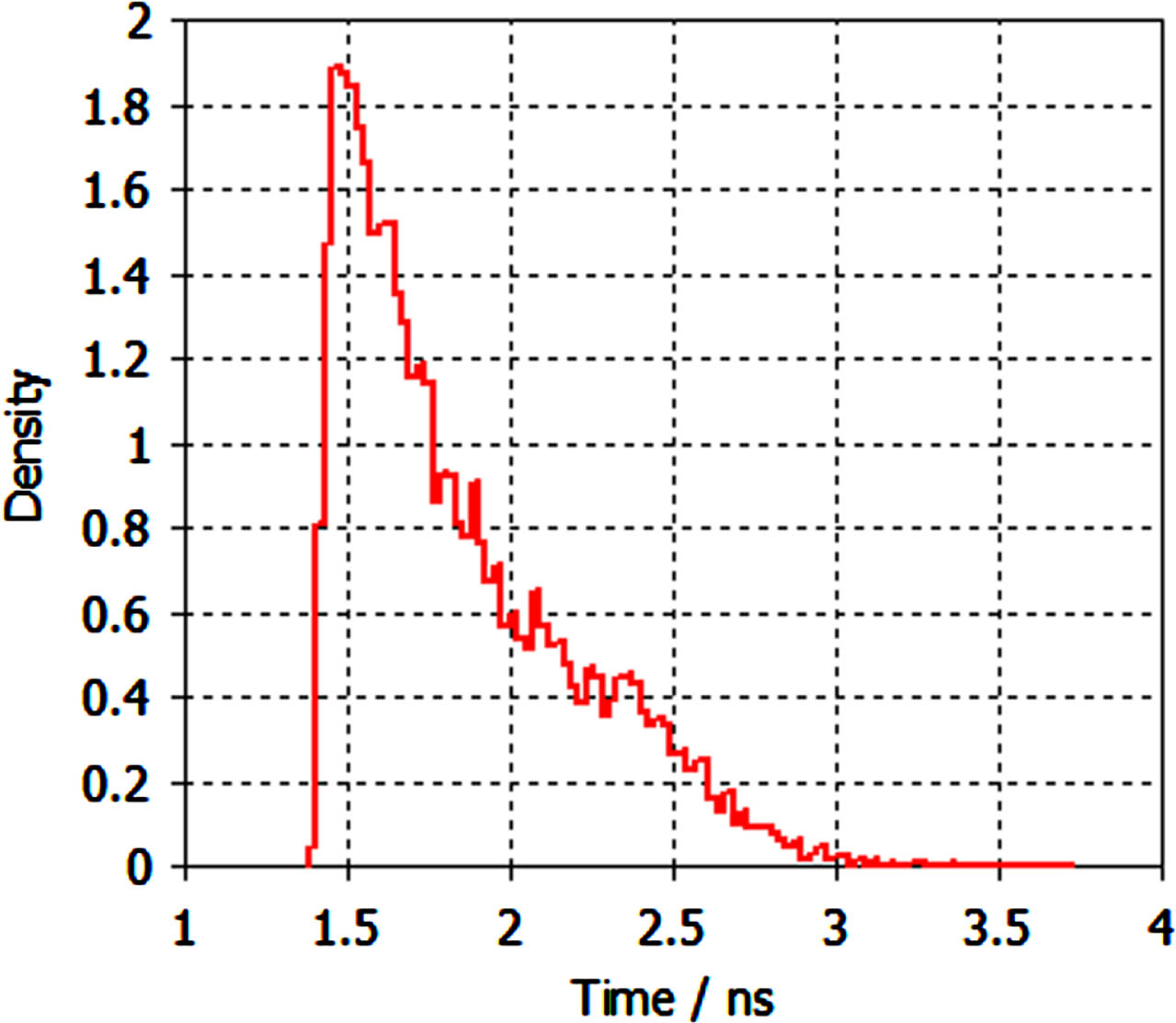
Electron transit time distribution.
Figure 11 shows the change in electron transit time dispersion under different anode voltages. As the anode voltage increases, the electron transit time dispersion initially decreases rapidly and then slows. The smaller the electron transit time dispersion is, the less pulse broadening occurs, resulting in narrower X-ray signal pulse widths and faster modulation speeds. Due to the completion of photoelectric conversion and X-ray generated by electron bombardment on the target in the photoelectric X-ray tube within a very short time, the resulting X-ray pulse broadening is negligible. Therefore, it can be inferred from the electron transit time dispersion that the modulation rate of the designed photoelectric X-ray tube can exceed 500 MHz at a 20 kV anode voltage. At an anode voltage of 40 kV, modulation rates greater than 1 GHz can be achieved.
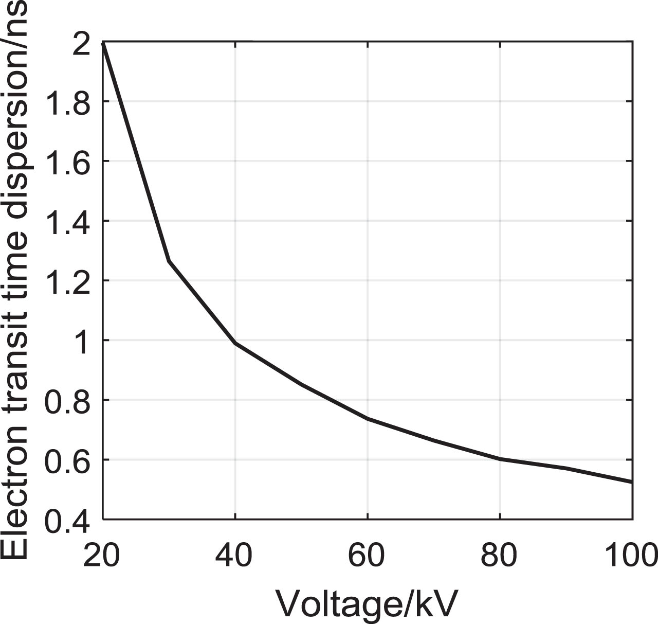
Electron transit time dispersion at different anode voltages.
The modulation speed of FFLMXRS depends on the modulation speed of the light source. However, if the modulation speed of the light source exceeds the maximum modulation speed of the photoelectric X-ray source, it will cause the characteristic photon signals of different time slots to overlap, affecting signal recognition. Therefore, the modulation speed of a single photoelectric X-ray source limits the maximum modulation speed of FFLMXRS. By increasing the tube voltage of the X-ray tube, the modulation speed of the photoelectric X-ray source can be further improved, but at the same time, the thermal load capacity of the anode target material should be considered after the power is increased.
Figure 12 presents the change curves for the normalized total X-ray counts, normalized characteristic X-ray counts, and peak-to-total ratio of each target under different thicknesses with an anode voltage of 20 kV. Both the total X-ray count and the characteristic X-ray count initially increase with the target thickness, reaching their maximum values before gradually decreasing. However, the thickness at which the characteristic X-ray count reaches its maximum is greater than the thickness at which the total X-ray count reaches its maximum. The peak-to-total ratio was determined by dividing the characteristic X-ray count by the total X-ray count. The peak-to-total ratio of the four targets increases as the target thickness increases. This indicates that the intensity contrast between the characteristic peak and the continuous spectrum becomes more pronounced with greater target thickness. Table 5 provides the thickness values for Cr, Fe, Ni, and Cu targets at which the total X-ray count and characteristic X-ray count are at their maximum.
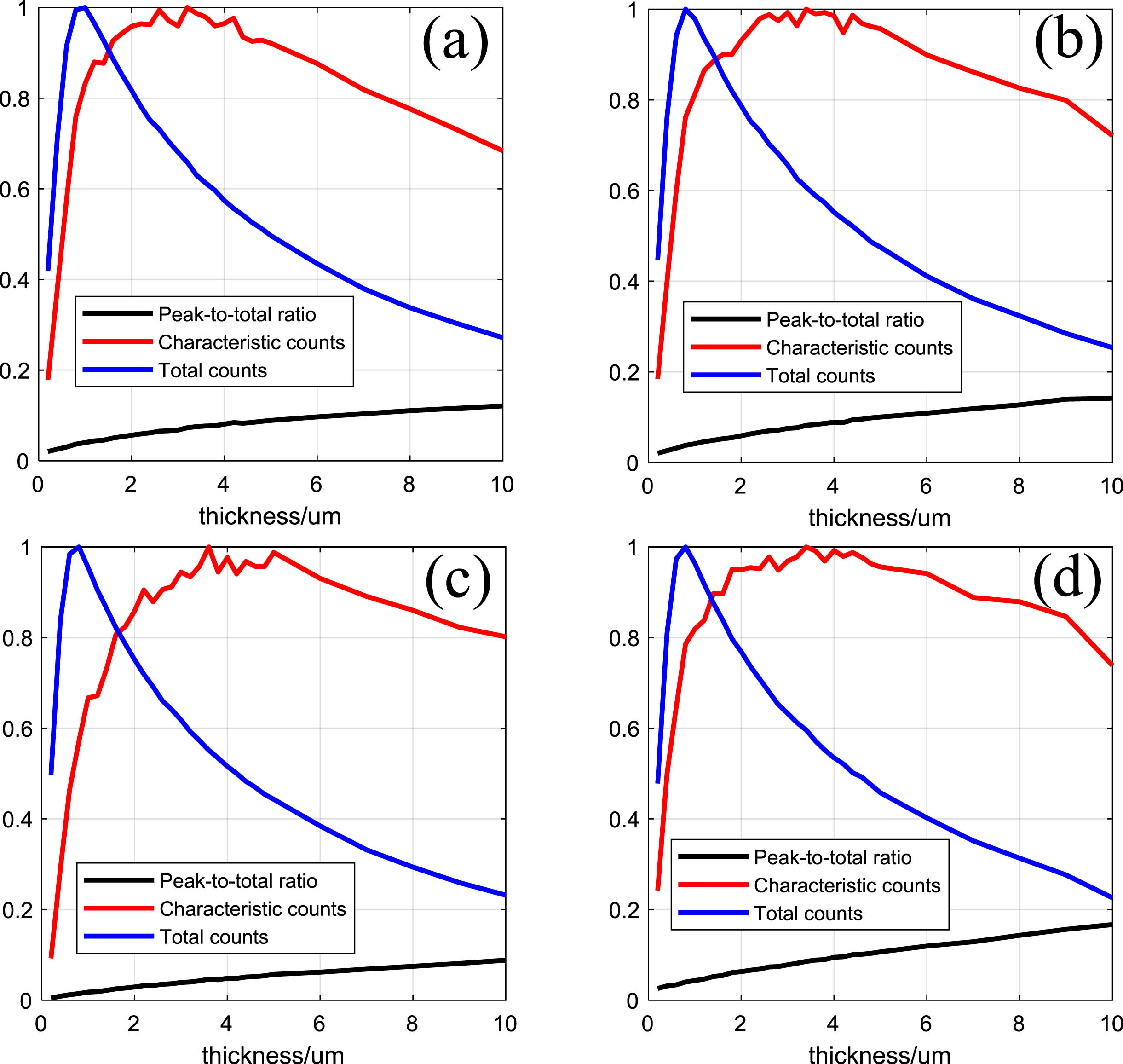
The relationship between the total number of photons normalized emitted, the number of characteristic photons normalized and the peak-to-total ratio and the thickness of the target. (a) Cr, (b) Fe, (c) Ni, (d) Cu.
Optimum target thickness of Cr, Fe, Ni and Cu
In the subsequent analysis, the representation of 16 X-ray spectral signals utilized the digits “0000” to “1111”. The first digit, from left to right, denotes whether the Cr target has been bombarded (0 for not bombarded, 1 for bombarded). The second digit denotes whether the Fe target has been bombarded. The third digit denotes whether the nickel target has been bombarded. The fourth digit denotes whether the copper target has been bombarded. Figure 13 displays the X-ray spectral signals generated when one or more targets are bombarded with optimal thicknesses. The simulation results show that a total of 15 highly distinguishable spectral signals can be generated based on the designed target component structure. It can be concluded that within one modulation period, the four kinds of targets can emit characteristic spectra in any combination, resulting in a total of 16 X-ray signals (including the absence of an X-ray spectrum denoted as “0000”). Despite the use of Cu as a tube wall material, the intensity of characteristic photons noise of Cu material generated is significantly lower than the number of effective signal photons.
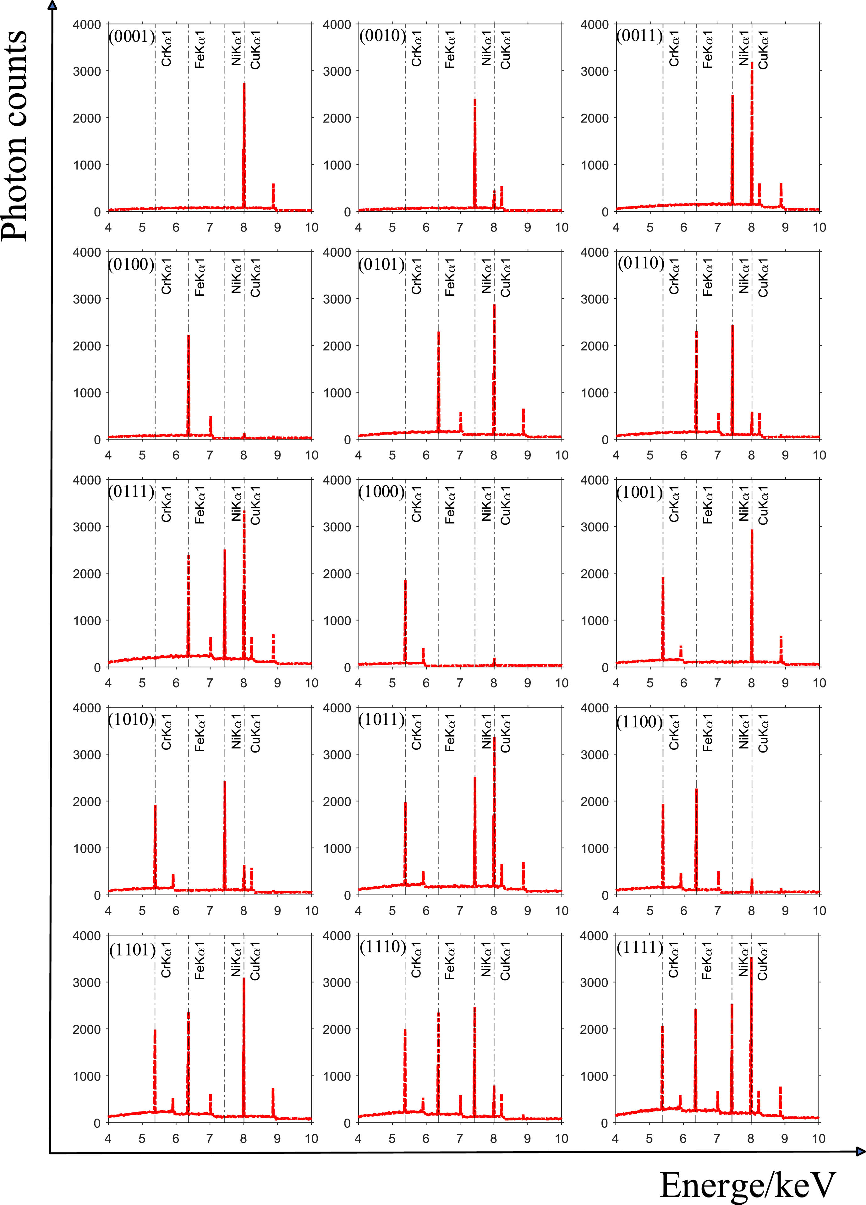
X-ray spectra signals at optimal target thickness.
Figure 14 depicts the temperature distribution and temperature change curve of the target module following continuous thermal power input during the 2000s. At thermal equilibrium in the 2000s, the maximum temperature at the focal point of the transmitted target module was 306.94°C. Upon increasing the thermal power input, it was observed that the maximum surface temperature of the target approached the melting point of copper, reaching 1050.8°C when the thermal power input was 90 W. Therefore, the designed transmission target assembly poses no melting risk at a continuous thermal power input of 20 W.
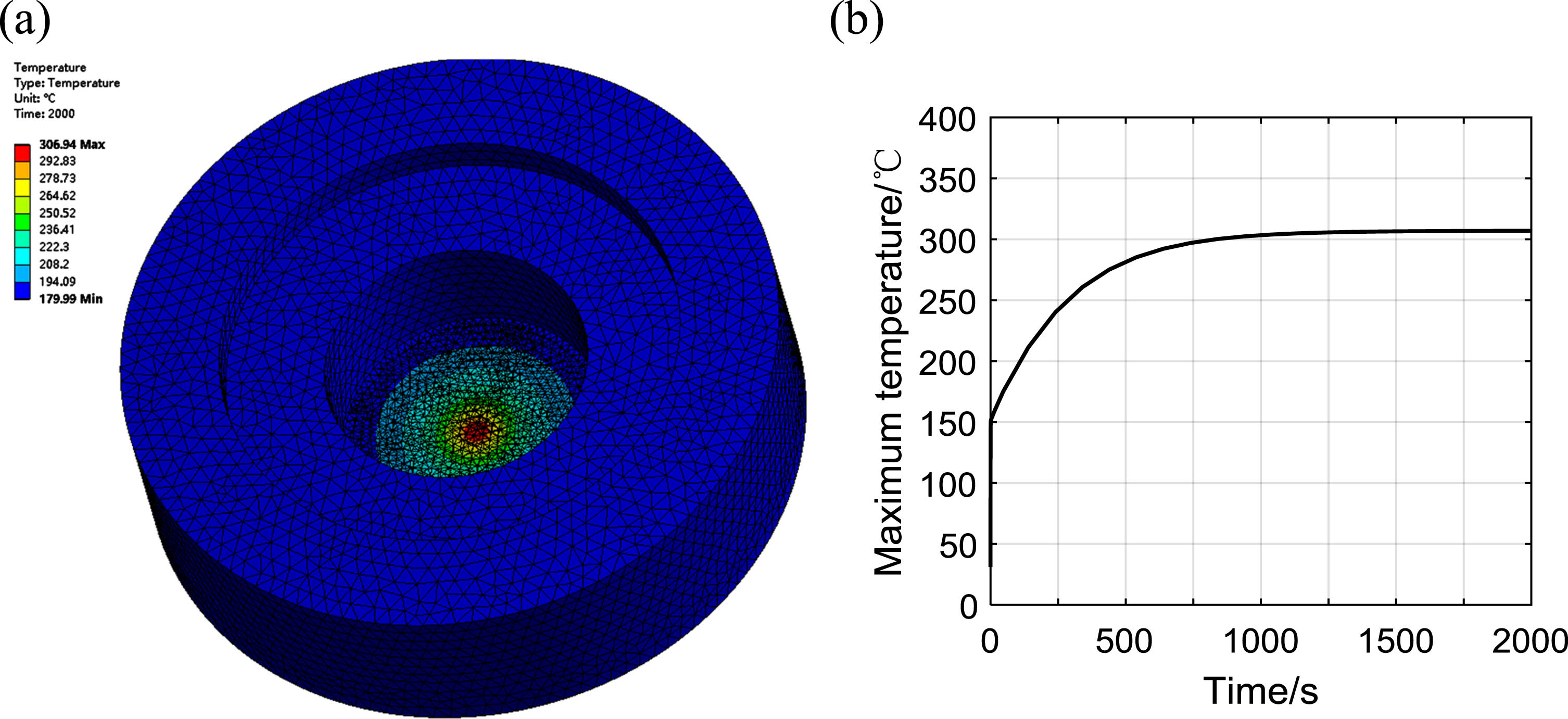
Temperature distribution of the target module and temperature change curve at the focal point in the 2000s after thermal power input. (a) Temperature distribution (b) Temperature variation curve at the focal point.
This paper presents the design of a four-tube four-target light source modulated X-ray source based on energy load information, accomplished through the design of a fast switching module of light channel based on FPGA and the design and simulation of a transmission photoelectric X-ray tube. The experimental results demonstrate that the designed light source channel fast switching module enables four parallel modulation level signal outputs at a modulation rate of up to 200 MHz. The simulation results reveal that under the tube voltage of 20 kV, the optimized focal radius of the transmitted photoelectric X-ray tube is 1.2 mm, the electron arrival rate is 90.4%, potentially reaching a modulation rate of 500 MHz, ensuring that it remains within the thermal limit. Compared to the previously developed muti-target modulated X-ray source, this X-ray source shows faster modulation speed while effectively suppressing noise inherent to X-ray spectral signals of different characteristics. The optimal target thickness of Cr, Fe, Ni and Cu is found to be 3.2μm, 3.4μm, 3.6μm and 3.4μm respectively, achieving higher characteristic X-ray intensity and improved anti-interference capability.
Footnotes
Acknowledgments
This study was supported by “the Fundamental Research Funds for the Central Universities, NO. NS2024054 ”.