
Abstract
A novel Astronaut Rehabilitative Training Robot (ART) based on a cable-driven mechanism is represented in this paper. ART, a typical passive force servo system, can help astronauts to bench press in a microgravity environment. The purpose of this paper is to design controllers to eliminate the surplus force caused by an astronaut's active movements. Based on the dynamics modelling of the cable-driven unit, a hybrid force controller based on improved credit assignment CMAC (ICMAC) is presented. A planning method for the cable tension is proposed so that the dynamic load produced by the ART can realistically simulate the gravity and inertial force of the barbell in a gravity environment. Finally, MATLAB simulation results of the man-machine cooperation system are provided in order to verify the effectiveness of the proposed control strategy. The simulation results show that the hybrid control method based on the structure invariance principle can inhibit the surplus force and that ICMAC can improve the dynamic performance of the passive force servo system. Furthermore, the hybrid force controller based on ICMAC can ensure the stability of the system.
Keywords
1. Introduction
With the development of the manned spaceflight project, the harsh environment inside the high speed moving spacecraft and complicated extra-terrestrial environments, etc., have had negative effects on astronauts. In these unfavourable circumstances, the microgravity environment has the most significant influence on astronauts. Space medicine research shows that long-term exposure to a reduced gravity environment may trigger adaptive and pathological changes of the human body, including osteoporosis [1], amyotrophy [2], cardiovascular dysfunction [3] and neurological diseases [4], etc. These changes are called ‘space adaptation syndrome’ (SAS) which is one of the main problems to be solved in the current development of the manned spaceflight project, since it seriously affects astronauts' health and their work. Corresponding research is necessary to overcome the adverse effects of weightlessness on astronauts, improve their physical and mental stability and ensure work efficiency. All this has great significance for the development of the manned spaceflight project.
As the mechanism of the physiological effects of a microgravity environment has yet to be elucidated, physical exercise is currently used by astronauts in the International Space Station (ISS) so as to overcome SAS. However, in a weightless environment, the traditional counter-gravity training made on the earth loses its effects. Crew members aboard the ISS usually adopt physical training in order to mitigate the impact of prolonged weightlessness on musculoskeletal and cardiovascular systems. A bicycle ergometer and treadmill are used by astronauts to keep cardiovascular fitness [3]. An Advanced Resistive Exercise Device (ARED) is utilized to prevent the amyotrophy of the pelvic limb and losses in bone mineral density [5]. This equipment has the weaknesses of a single function and a large volume and mass. Investigations show that the training efficiency of the astronauts aboard the ISS is low, since their time and effort is mainly taken in repositioning and assembling these devices. The reference [6] proposed a Combined Countermeasure Device (CCD) to integrate resistance training and cardiovascular conditioning with a balance training component. CCD produces noise for using pneumatic components. However, the effectiveness of balance training component is also not ideal. To build back muscles, astronauts also do exercises using a rower ergometer. The bench press mainly trains the muscle group of the chest and the arms, especially the pectoralis muscles and the extension muscles of the upper limb. It needs a large number of bones and muscles to coordinate effectively. The bench press significantly increases the strength and working ability of the upper limb. However, none of these existing facilities can realize the function of upper-body training for astronauts. A novel Astronaut Rehabilitative Training Robot (ART) (Fig. 1) based on a cable-driven mechanism is put forward in this paper. An ART could assist astronauts with bench press training in a microgravity environment by simulating the barbell of a gravity environment [7]. While performing rehabilitation treatment on musculoskeletal disuse changes of astronauts' upper limb (e.g. amyotrophy), it can enhance the strength and the operation capability of the upper limb. The ART features a simple structure, a modular and reconfigurable design, and is energy efficient and pollution-free, etc. These characteristics all determine that the ART is suitable for rehabilitation in confined environments, such as that of a spaceship or space station.

Astronaut rehabilitative training robot
The ART (Fig. 1) is a typical man-machine cooperation system. During the process of a bench press, the astronaut performs active movements, followed by the ART performing passive movements. According to the motion state of the astronaut, the ART could truly simulate and provide the same gravity and inertial force as the dynamic force of the barbell in a gravity environment. The ART is a typical passive force servo system [8]. The key to the design of the controller of a passive force servo system is to inhibit or even eliminate the surplus force, the existence of which could seriously affect the control's precision. A hybrid control based on the structure invariance principle is a common compensation method, in practice [9, 10]. This method requires accurate system mathematical models, but in reality it is difficult to achieve decent dynamic performance for such unhelpful factors as strong coupling, nonlinearity and time-variable parameters, etc. [11]. The uncertainty of the system model was taken into account in reference [12], which adopted a quantitative feedback theory (QFT) in designing the servo force control system grounded on the minor changes of the load-carrying object features [13]. The dual loop control structure based on the disturbance observer (DOB) was presented in [14], providing a valuable method for the design of a passive force servo system [15]. With the development of intelligent control theory, neural networks have been applied to a wide range of passive force servo systems [16]. Reference [17] proposed a PID controller based on a RBF neural network and the dynamic load control precision was improved. A hybrid control strategy CMAC with the improvements of a balanced learning method, optimal weights and an adaptive learning rate was proposed in reference [18]. The proposed strategy could ensure the stability of the system with high tracking precision and good dynamic characteristics. Compared with other intelligent control theories, a CMAC neutral network is suitable for real-time control due to such advantages as its simple structure, its ability to learn fast and generalize well, and its ease of implementation by hardware, etc. [19–21]. The premise of surplus force compensation in the above control strategies for the passive force servo system is that the active motion of the actuators can be measured. Moreover, the fluctuation of the dynamic load cannot destroy the actuators. Since the motion of the astronaut is unpredictable in a man-machine cooperation system of an ART, a hybrid control based on the structure invariance principle cannot be directly used to compensate the surplus force. In addition, the load will fluctuate with the learning process of CMAC, and the drastic fluctuation of the dynamic load may endanger the astronaut. According to what has been stated above, a hybrid force controller based on ICMAC is introduced in this paper so as to ensure stability and the good dynamic performance of the ART, which can offer astronauts safer training.
This paper is structured as follows: In Section 2, the building of the dynamics model of the cable-driven unit is detailed after the brief introduction of the ART. In Section 3, the proposal of the hybrid force control based on the ICMAC control strategy is elaborated. In Section 4, the proposal of the planning method of cable tension is treated. In Section 5, the building of the simulation model of the man-machine cooperation system and the conduct of five simulation experiments are shown. Finally, conclusions are drawn in Section 6.
2. Dynamics Model of the ART
2.1 Composition and Working Principle of the ART
The mechanical structure of the ART is shown in Fig. 1. The frame of ART is fixed to the spaceship or space station in order to install the cable-driven unit. With a length of 2m and a width of 1m, the whole frame occupies less space. As shown in Fig. 2, the modularization concept is adopted by the design process of the cable-driven unit so as to ensure convenience of transportation, assembling and maintenance. Six cable-driven units are placed on the frame symmetrically. The flexible cable, whose terminal is connected with the bench press bar under the guidance of the guide pulleys, twines around the traction pulley. Each end of the bar connects 3 flexible cables respectively. A bench is set up across the frame to assist the astronaut to perform a bench press. The astronaut and ART make up a man-machine cooperation system.

Cable-driven unit without the cover
During the training process, the astronaut can lift the bench press bar according to his own requirements. The real-time tension of each flexible cable is planned by the controller of the ART in accordance with the motion state of the astronaut to ensure that the resultant dynamic load is equal to the sum of the gravity and inertial force of the barbell in the gravity environment. The tension of the flexible cable is adjusted by a torque motor via the traction pulley. The upper computer collects the output of the encoders to detect the length of the flexible cables and deduces the motion state of the bench press bar using forward kinematics. Tension sensor detects the real-time tension of the flexible cable, which is then transmitted to the upper computer. The tension sensor is fixed inside the driven unit to avoid the measurement error caused by the vibration of the tension sensor.
2.2 Dynamics Model of the Cable-driven Unit
Due to the modular design of the cable-driven unit, each cable-driven unit of the ART has the same dynamics characteristics. Taking one cable-driven unit as the research object, the dynamic model of the cable-driven unit can be built by a mechanism theory. The mechanism model of the driven unit based on Fig. 2 is shown in Fig. 3.

Mechanism model of the cable-driven unit
In the mechanism model of the cable-driven unit (see Fig. 3):
u motor armature input voltage, V
L motor armature inductance, H
R motor armature resistance, Ω
e motor armature back-EMF, V
i motor armature current, A
Ce motor back-EMF constant, V·s/rad
Cm motor torque constant, N·m/A
Tm motor driving torque, N·m
Jm inertia of motor rotor and traction pulley, Kg·m2
Bm motor armature viscous friction coefficient, N·m·s/rad
Tl load driving torque, N·m
θm angular displacement of the traction pulley, rad
r radius of the traction pulley, m
F tension of the flexible cable, N
x the linear displacement of the traction pulley, m
M mass of the flexible cable, Kg
B damping coefficient of the flexible cable, N·s/m
K stiffness of the flexible cable, N/m
xp displacement of the flexible cable terminal, m
Remark: Using the International Unit, the numerical magnitude of the cable stiffness (1×10⁵ N·m) is much greater than that of the cable quality (0.1Kg) and damping (1×10⁻⁵N·s/m). Therefore, the impact of the flexible cable can be neglected and the cable tension F can be regarded as the force exerted on astronauts.
For the permanent magnet DC torque motor, the armature circuit equation is characterized by:

Where:

The motor driving torque is proportional to the motor armature current:

During the operation process, the motor driving torque T m is used to overcome the load torque, the inertial force of the motor rotor and traction pulley and the viscous friction force of the motor rotor. According to Newton's second law, the torque equilibrium equation is described as:

The cable tension F is exerted on the astronaut by the flexible cable. The flexible cable can be equivalent to a mass-spring-damping model. The force equilibrium equation is:

In Equation (5), the tension of the flexible cable can be measured by the tension sensor.
In addition, the displacement of the cable is related to the angular displacement of the traction pulley by:

The tension of the flexible cable is related to the load driving torque by:

Rewriting Equations (1)∼(7) by utilizing the Laplace transform and then combining these equations, the simultaneous dynamic equation of the cable-driven unit can be deduced as:

Where:
J0 = Mr2 + Jm is the equivalent inertia,
B0 = Br2 + Bm is the equivalent viscous friction coefficient,
Vp(s) = sXp(s) is the velocity of the flexible cable.
According to Equation (8), the transfer function block diagram of the cable-driven unit can be expressed as in Fig. 4.

Transfer function block diagram of the cable-driven unit
According to Equation (8) and Fig. 4, the movement of the flexible cable vp is a disturbance of the cable-driven unit system. In the ART man-machine cooperation system, the error between the actual dynamic load and the ideal dynamic load is related with system parameter variation, sensor errors and the active movements of the astronaut, etc. The error caused by astronaut's active movement is defined as the surplus force. The influence of the surplus force - which is also the key problem to be solved in designing the controller - on the control precision of the ART is severe.
3. Control Strategy
For the cable-driven unit system with a double input single output shown in Fig. 4, its output F is the resultant force of motor driving torque Tm controlled by a control voltage u and the surplus force caused by the movement of the astronaut xp. To ensure the system's stability and high performance, the controller has to acquire enough information from the two inputs. With regard to the transfer function (8), we designed the hybrid force controller to control the output of the system F and to compensate for the disturbance caused by the astronaut. Considering such factors as the system's nonlinearity and uncertainty, we employ ICMAC to improve the dynamic performance and control accuracy of the dynamic load.
3.1 Hybrid Force Controller Design
The block diagram of the hybrid force controller is shown in Fig. 5. There are three objectives for the controller:

Block diagram of the hybrid force controller
Employ a PID controller to conduct a series correction of the passive force servo system;
Use the input signal (the desired cable tension Fd) for feedforward compensation;
Compensate the disturbance indirectly based on the structure invariance principle.
3.1.1 PID Controller
In this control strategy, the PID controller - whose major task is to ensure the stability of the system - can track the input signal and inhibit the disturbance and uncertainty of the cable-driven unit system. However, the PID controller can only partially inhibit the disturbance and the uncertainty of the system. The requirement of an ideal dynamic tracker is hard to meet using a PID controller alone.
3.1.2 Feedforward Compensation
On the basis of Fig. 5, the feedforward compensator Gr(s) can be described as:

Gr(s) can realize the perfect tracking control theoretically and a zero tracking error can be achieved. As Gr(s) does not affect the characteristic equation of the system, the system stability is not affected. Moreover, the control precision can also be improved.
As to the engineering application, given that the order of D(s) is higher than the order of N1(s), the forward channel contains higher-order derivative terms. Thus, the ideal compensator Gr(s) cannot be physically realized. In the design of Gr(s), higher-order derivative terms can be neglected to make the compensator Gr(s) approximately match Equation (9).
3.1.3 Indirect Disturbance Compensation
In the ART man-machine cooperation system, the state of the astronaut's active movement is hard to measure. Therefore, the direct compensation of the disturbance cannot be achieved. In Fig. 5, the disturbance Vp(s) is measured indirectly through G1(s) and G2(s) together with a compensator B(s) which is designed to compensate Vp(s).
The transfer functions of the measuring channels are as follows:

The transfer function of the disturbance compensating channel is as follows:

In the actual engineering application, the input of G2(s) is the cable tension F detected by the tension sensor; the input of G1(s) is the control signal U of the cable-driven unit system. Input signals of G1(s) and G2(s) are easy to obtain. For its physical realization, the higher-order derivative terms of G1(s), G2(s) and B(s) are all neglected. The transfer function of G1(s), G2(s) and B(s) approximately satisfy Equation (10) and Equation (11) respectively.
Theoretically, the hybrid force controller ensures the stability of the cable-driven unit system, whose dynamic performance and control precision are better than those of the PID controller. Actually, the theoretical model of the cable-driven unit cannot perfectly match the practical object because of the existence of the system's uncertainty. In addition, the higher-order derivative terms are neglected in application. The experimental results may not be completely consistent with the theoretical results. Therefore, neural network control is adopted to overcome these drawbacks.
3.2 Design of ICMAC
The hybrid force controller based on ICMAC proposed in this paper is shown in Fig. 6. Its working principle is as follows:

Block diagram of the hybrid force control based on ICMAC
All the weights of ICMAC, wi, are zero in the initial state. The ART works stably under the control of the hybrid force controller.
During the operation procedure, the desired dynamic load and cable velocity are used as input signals to activate the corresponding addresses.
The output of ICMAC, Uc, is the algebraic sum of the activated addresses' weights. The output of the hybrid force controller based on ICMAC can be expressed as:

Where (Up + Ur + Ub) is the output of the force controller.
At the end of the control cycle, the output of the PID controller is used to modify the weight of the ICMAC by utilizing the balanced learning algorithm. Next, the ICMAC gradually replaces the PID controller. The introduction of ICMAC improves the tracking precision and the dynamic characteristics.
3.2.1 Description of ICMAC
The schematic diagram of ICMAC with a double input single output is shown in Fig. 7, while the architecture of the two-dimensional ICMAC is shown in Fig. 8. According to Fig. 7 and Fig. 8, the working principle of ICMAC is summarized as follows.

Schematic diagram of ICMAC with double inputs and a single output

Architecture of a two-dimensional ICMAC
Remark: for a better illustration, the resolution ratio of the two inputs of ICMAC (Fd & vp) are nE1 = nE2 = 9.
For a given input
Each state with nl floors is composed of nb blocks. n l elements can be accumulated as a block. In Fig. 8, nl = 4, nb=3. A, B, a and b are all complete blocks. C and c are also called blocks, but they are incomplete.
The combination of blocks which are on the same floor but in different states can form an area; such areas can be called addresses or hypercubes. For example, the areas Aa, Ab, Ac, Ba, Bb, Bc, Ca, Cb and Cc are addresses for storing data, while the combination of Ad or Ae (which are on different floors) does not exist. Therefore, there are 36 hypercubes (nh=36) to store 81 states, as in Fig. 8. The data memory space is compressed.
The number of hypercubes activated by

Where aj = 1, j = 1, 2, …, nl, aj indicates whether the hypercube j is activated by
According to Fig. 7 and Fig. 8, after the quantification of the input (Fd,vp), the input is mapped to (4,4) of the input states. The hypercubes Bb, Ee, Hh and Kk are activated, and the algebraic sum of the weights of the hypercubes (w5, w14, w23, w32) is the output of ICMAC.
3.2.2 Address function
For the ICMAC proposed in this paper, each input variable is divided equally into nE (nE=nl(nb-1)+1) elements. The number of the input states is (nl(nb-1)+1)2, and the number of hypercubes is nl·nb2. In order to avoid the data collision and to compress the data memory space, the reference [22] employed an addressing function to produce the flag of the activated hypercubes. The input (Fd, vp) can activate nl hypercubes. Define the addressing function of each hypercube as s(j), j=1,2 … nl. The addressing function s(j)=F(s1,s2,j) can be obtained by the following steps:


3.2.3 Online Learning Algorithm
The astronaut becomes tired after a long duration spent training, and the velocity and the amplitude of the bench press decrease gradually during the training period. To keep the decent dynamic characteristics of the ART, the weights of the CMAC should be updated in the shortest possible time according to the motion state of the astronaut. Therefore, unnecessary weight modifications have to be avoided as much as possible. Those weights which have more learning time, more learning experience and higher creditability should be changed as little as possible. Meanwhile, those weights activated by special circumstances (e.g., abrupt acceleration or suspension) have less learning time, fewer learning experiences and lower creditability. These weights should be modified as much as possible so as to accommodate the special circumstances. In order to achieve better dynamic performance in both normal and special circumstances, the learning algorithm of the ART controller has to balance the correction value of the creditable weights with more learning times and the correction value of incredible weights with fewer learning times. In our research, the balanced learning algorithm is adopted to modify the weights of ICMAC [23, 24].
Select the output of the PID controller Up as the training signal, the balanced learning algorithm (also called the weight modification rule) of ICMAC is as follows:


Where η is the learning rate, f(j) is the learning time of the hypercube j, k is the balanced learning constant representing the degree of responsibility that the activated hypercubes should take for the current error, α is the inertial coefficient - which can avoid the overcorrection of weight - and wj(t) is the weight of the jth hypercube at time t.
4. Cable Tension Planning
The so-called cable tension planning aims to schedule the real-time cable tension according to the mass of the barbell M to be simulated and the movement state of the flexible cable xi (i=1, …, 6). In a gravity environment, the dynamic load of the bench press is composed of gravity and inertial force. During training, gravity is a constant force while the inertial force is in proportion to the acceleration of the barbell. Therefore, it is necessary to plan the real-time cable tension in accordance with the movement state of the astronaut. In the meantime, the tension of each cable changes with the movement of the bench press bar correspondingly. Consequently, a corresponding planning is also required.
Assume that the length of the 6 flexible cables at any time is x1, x2, x3, x4, x5 and x6 (see Fig. 9). xi (i=1, …, 6) can be measured by the encoder of the cable-driven unit. The heights of the two ends of the bench press bar above the frame are:

Structure sketch of ART man-machine cooperation system

Where:

The dynamic load to be simulated by the ART during the training process is as follows:

Where g is the gravity acceleration, and ḧ1 and ḧ2 are the acceleration of the bench press bar's respective ends.
The existence of the lateral force in the process of the bench press would endanger the astronaut and so the resultant force at each end of the bar should be vertical and downward throughout the process. The controllable workspace of the ART is shown as the shadow part in Fig. 9. As long as the projection of point G1 and point G2 is inside the shadow area, a vertical downward resultant force can be realized at point G1 or G2.
The relationship between the cable tensions at point G1 and the configuration of the ART can be expressed as:

The meaning of a, β, ψ and φ in Equation (19) is as is shown in Fig. 10. a, β, ψ and φ change simultaneously with x1, x2 and x3. Fd4, Fd5 and Fd6 can be obtained in the same way.

Decomposition of the dynamic load
5. Simulation Research on the Man-machine Cooperation System
5.1 Man-machine Cooperation System Modelling
The simulation model of the man-machine cooperation system (see Fig. 11) was built by utilizing MATLAB/Simulink software and the dynamic characteristics of the system were simulated. The model mainly includes cable tension planning, force controllers, cable-driven units, an astronaut model, encoders and tension sensors, etc.

Simulation model of the ART man-machine cooperation system
The muscles of the upper limb and chest play a major role when astronauts do a bench press. Consequently, the human model was simplified as a six-bar linkage (see Fig. 9), including the upper limb, the chest and the bench press bar. The astronaut model was built by using the MATLAB SimMechanics toolbox and the parameters of the linkages were set in accordance with the actual characteristics of the human body and the bench press bar. The weightless environment was built by setting the machine environment module of the SimMechanics toolbox. The cable-driven unit models and force controllers were built based on Fig. 4 and Fig. 6 respectively. The real-time dynamic load and the cable tension were planned in accordance with Equation (16) and Equation (19).
5.2 Simulation Results
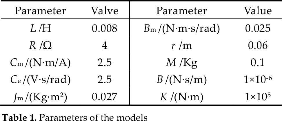
The simulation research of the man-machine cooperation system model shown in Fig. 9 was conducted in order to confirm the effectiveness of the hybrid force controller based on ICMAC. The actual parameters of the models used in the simulation research are listed in Tab. 1.
Parameters of the models
The parameters of the PID controller are:

The parameters of ICMAC are chosen as:

Assume that the bench press bar does not tilt or rotate during the process of the bench press, i.e., that the bar moves up and down on the same plane and that the heights of the two ends of the bar stay the same. To ensure the effectiveness of the training and to prevent damage, the speed of the bench press should not be too fast. Moreover, any sudden starting or stopping should also be avoided. Assume that the motion law of the bench press bar is:

Also, further assume that the mass of the barbell M to be simulated is 30Kg and that the acceleration of the gravity g is 10m/s2. Then, according to Equation (18), the curve of the dynamic load is shown in Fig. 12, which illustrates that the additional dynamic load (inertial force) caused by the astronaut's movement can be as much as 37N. Compared with the constant dynamic load 300N, the dynamic load planned by Equation (18) is consistent with the actual training dynamic load.

Curve of the dynamic load
To ensure that the resultant force at each end of the bench press bar is vertical downwards, the desired tension curve of each cable based on Equation (19) is illustrated in Fig. 13, where Fig. 13–(a) is the desired tension of cable 1 and 4, and Fig. 13–(b) is the desire tension of cable 2, 3, 5 and 6. Compared with the dynamic load of the ART, the cable tension of each cable-driven unit can be obviously reduced and so can the motor-driving torque. Accordingly, the volume of the cable-driven unit can be reduced. This means that the ART can be transmitted and assembled easily.

Cable tension
Although the desired tension and the movement state differ from cable to cable during the working process, they do not affect the performance of the controllers much, due to the modular design of the cable-driven unit. In this paper, the dynamic performance of controller_1 is tested to confirm the effectiveness of the control strategy.
(1) The PID Control
When the PID control is adopted, the dynamic response of the system is shown in Fig. 14. fd1 is the desired cable tension and f1 is the actual cable tension. The bench press started at t=1s. The amplitude of the tracking error was 15N, meaning that the amplitude of the surplus force is 15N. As can be seen from Fig. 14, with low control precision the capability of the PID to inhibit the surplus force is not ideal. Thus, it cannot meet the training need of the astronaut. The excessive surplus force may endanger the health and safety of astronauts.

Cable tension curve and tracking error based on the PID control
(2) Hybrid Force Control
We performed a simulation study on the hybrid force controller illustrated in Fig. 5. Fig. 15 is the dynamic response curve, where Fig. 15–(a) is the tracking curve of cable tension and Fig. 15–(b) is the tracking error. The bench press also started at t=1s. According to Fig. 15, the actual cable tension is more consistent with the desired cable tension and the dynamic performance of the system controlled by the hybrid force controller is better than that of the system controlled by the PID controller.

Cable tension curve and tracking error based on hybrid force control
Although the surplus force is inhibited and the control accuracy is improved, phase lag and amplitude decay still exist. The amplitude of the tracking error is 2N (see Fig. 15–(b)). With any increase in the frequency of the bench press, the dynamic performance of the system may deteriorate. As such, it is necessary to adopt ICMAC in order to improve the dynamic performance of the system.
(3) Hybrid Force Control Based on ICMAC
We performed a simulation study of the control strategy, as shown in Fig. 6. The result is shown in Fig. 16, where Fig. 16–(a) is the tracking curve of the cable tension and Fig. 16–(b) is the tracking error. According to Fig. 16, the introduction of ICMAC can reduce the tracking error compared with the hybrid force control. The amplitude of the tracking error is about 0.5N and the tracking error is deceased by approximately 75%. From Fig. 16–(b), along with the gradual decrease of the tracking error as time extends, the dynamic performance of the system becomes better.

Cable tension curve and tracking error of a hybrid force control based on ICMAC
(4) The Influence of The Motion Law
The motion law of the bench press changes with time for the tiredness of the astronaut, etc. In such circumstances, a simulation study on the man-machine cooperation system was performed to test the control strategy. Suppose it takes more time to finish one bench press. The motion law of the bench press bar can be expressed as:

The simulation result is as shown in Fig. 17. During the bench press, the astronaut began to slow down at 12s. At the beginning, the amplitude of the tracking error increased slightly (around 1N). After two bench press cycles, the tracking error decreased markedly. This illustrates that the system can maintain decent dynamic performances when the motion law of the bench press changes because of the introduction of ICMAC.

The cable tension curve and tracking error in the case of the change of motion law
(5) Stability of the Hybrid Force Control Based on ICMAC
Since long-duration learning may result in system divergence, it is necessary to test the stability of the hybrid force controller based on ICMAC. According to Equation (20), it costs the astronaut 4s for one bench press. In prolonging the simulation time to 500s, 125 bench presses can be done during this period. This is long enough to test its stability.
Fig. 18 shows that the tracking error of the system converges gradually without any tendency to diverge. The introduction of ICMAC not only improves the dynamic performance of the system and further inhibits the surplus force, but it also ensures the stability of the system.

Tracking error of the hybrid force control based on ICMAC for 500s
6. Conclusion
In this paper, a hybrid force controller based on ICMAC was designed on the basis of the dynamics model of a cable-driven unit. A balanced learning method was used to improve the learning speed of ICMAC. Furthermore, a planning method was proposed so as to plan the desired tension of each flexible cable. The validity and effectiveness of the proposed control strategy were verified by software simulation. The simulation results show that the proposed control strategy has the following advantages:
A hybrid force control based on the structure invariance principle can effectively inhibit any surplus force and the stability of the system and the safety of the astronaut can also be ensured;
ICMAC can improve the training effect and dynamic performance of the ART;
Due to its ability to self-learn, the use of the ART can be expanded. It can adapt to different astronauts and movement states.
The research in this paper provides a theoretical basis for the controller design of an ART. The force control performance of the ART can be improved so that it can realistically simulate the bench press process of a gravity environment. This research work could significantly enhance the training effect of the bench press in a microgravity environment and astronauts would be able to develop a better body condition and work efficiency. Our future research would be to perfect its safety measures and prepare for experiments with human beings.
Footnotes
7. Acknowledgments
This work is supported by the National Nature Science Foundation of China under grant No. 61175128, the National High Technology Research and Development Programme of China under grant No. 2008AA040203 and the Research Fund for the Doctoral Programme of Higher Education of China under grant No. 20102304120007.