
Abstract
We present a combined machine learning and computer vision approach for robots to localize objects. It allows our iCub humanoid to quickly learn to provide accurate 3D position estimates (in the centimetre range) of objects seen.
Biologically inspired approaches, such as Artificial Neural Networks (ANN) and Genetic Programming (GP), are trained to provide these position estimates using the two cameras and the joint encoder readings. No camera calibration or explicit knowledge of the robot's kinematic model is needed.
We find that ANN and GP are not just faster and have lower complexity than traditional techniques, but also learn without the need for extensive calibration procedures. In addition, the approach is localizing objects robustly, when placed in the robot's workspace at arbitrary positions, even while the robot is moving its torso, head and eyes.
1. Introduction
Today the majority of robots are still applied in industrial settings, where they are mainly used as programmable machines to solve automation tasks with pre-defined, pre-programmed actions in very structured environments. In recent years however, the field has been moving towards extending the use of robotic systems into areas where they can co-exists and help humans [1]. Proposed applications range from household tasks, helping in a hospital, to elderly care, grocery shopping, etc. A main hurdle is that the world humans live in is an inherently ‘unstructured’ and dynamic environment.
A robot needs to be able to perceive and understand its surroundings, as the state of its workplace and the objects in it can no longer be known a priori. The robot has to rely on its sensory feedback to build a model of its surroundings. Although perception for robotic systems has been investigated for a long time, e.g., [2–4], it remains a difficult issue to solve in robotic systems [5]. A spatial understanding, i.e., to identify and localize objects autonomously and robustly with respect to itself, is crucial for motion planning, obstacle avoidance and finally object manipulation. We aim to provide our humanoid robot with the means to estimate the positions of objects relative to itself. We do so by using a machine learning technique providing predictions of the objects' positions.
2. Problem Statement and Previous Work
Localizing objects in 3D given two images from cameras in different locations is widely known in the computer vision literature as the ‘stereo vision’ problem. Prevalent approaches to this issue are based on analytical projective geometry and photogrammetry. Cameras photographing the same scene from two different locations provide different 2D projections of the 3D environment. If the ‘intrinsic parameters’ that specify each camera's projection from 3D to 2D, as well as the ‘fundamental matrix’, i.e., the rigid-body transformation between the left camera's reference frame (CSL) and the right camera's (CSR), are known, and if there are features of the scene that can be identified in both images, then the 3D locations of those features can be triangulated. For a thorough review of approaches based on this principle we refer to [6].
While traditional stereo vision approaches, based on projective geometry, have been proven effective under carefully controlled experimental circumstances, they are not ideally suited to most robotics applications. Intrinsic camera parameters and the fundamental matrix may be unknown or time varying, and this requires the frequent repetition of lengthy calibration procedures, wherein known, structured objects are viewed by the stereo vision system, and the required parameters are estimated by numerical algorithms.
Assuming a solution to the standard stereo vision problem, applying it to a real physical robot to facilitate object manipulation remains a challenge. In many robotics applications, it is somewhat inconvenient to express the environment with respect to a camera. For example, from a planning and control standpoint, the most logical choice of coordinate system is CSWorld (see Figure 1), where the reference frame at the base of the manipulator does not move with respect to the environment. In order to transform coordinates from CSL or CSR to CSWorld, such that we can model objects and control the robot in the same frame of reference, an accurate kinematic model of the robot is required. If such a model is available, it must be carefully calibrated against the actual hardware, and even then its accuracy may be limited by unmodelled nonlinearities. In some robots no kinematic model is available or they lack an accurate model due to their highly anthropomorphic design, eg., the CRONOS robots 2 . We are interested in developing an approach to object localization that is robust enough to be deployed on a real humanoid robot and to facilitate on-line motion planning for object manipulation tasks. The method must therefore be able to cope with camera motion, as objects will be localized while the robot is controlling its gaze (head and eyes) and reaching (torso). In particular, the fundamental matrix will vary as a function of pan and vergence of the eyes, and the position and orientation of the two cameras (the head) will vary as a function of the state of the torso and neck.

The localization problem, illustrated using the iCub kinematic model: images from cameras located at CSR and CSL are processed to express the object's position wrt. CSWorld.
Our experimental apparatus is the iCub humanoid robot [7], an open-system robotic platform developed within the EU funded RobotCub project. Our configuration consists of a 41 degree-of-freedom (DOF) upper-body mounted on a pedestal (see Figure 2). The iCub is an excellent experimental platform for cognitive and sensorimotor development, and embodied Artificial Intelligence (AI) [8]. In addition, in our setup, it is particularly well-suited for object manipulation research. The hands of the iCub allow for manipulation of objects of daily living, e.g., cups, mugs, tea boxes, etc. These objects are the right size for manipulation by the robot.

The iCub humanoid robot as used in our experiments.
To our knowledge, no machine learning techniques have been investigated so far to facilitate visual and spatial perception. Several different localization systems have previously been developed for the iCub. One method currently implemented for performing stereo vision is based on log-polar image representation. This is a biologically inspired approach that mimics the retina of the eye. Camera images are projected by a log-polar transform before typical stereo vision depth estimation algorithms can be used to analyse this view. A full review of this technique for robotics applications can be found in [9]. The currently available implementation only supports a static iCub head, putting the object position in the CSR or CSL coordinate frame, but could be extended to the full iCub torso subject to a precise kinematic model.
The ‘Cartesian controller’ module, available in the iCub software repositories, also provides basic 3D position estimation functionality [10]. This module works well on the simulated iCub, however, its performance on the hardware platform is weak. One reason for this is its need for an accurate robot model and camera parameters, which necessitates a thorough configuration before using this module on the hardware. For example, our iCub cameras were not mounted precisely as described in the CAD model, and could not to be fixed mechanically due to design choices. This leads to large estimation errors when using the module.
One of the few techniques for 3D object localization, which aims for robustness to camera motion, is described in [11]. The approach computes the time-varying fundamental matrix, facilitating the estimation of the relative position of two objects (e.g., the hand and an object to grasp). However, it does require a precise kinematic model of the robot.
The precision of all of these approaches depends upon a very accurate kinematic model (or estimation thereof) of the robot. Currently however, no module estimating the kinematics of the iCub exists, this is partly due to the openly available construction models and thorough calibration procedures that should be applied regularly.
For other robotic platforms, machine learning has been used to estimate the kinematic model, for example, Bongard et al. employed sensory feedback to learn [12], but without high-dimensional sensory information such as camera images. A different approach is to learn the inverse kinematics of a robotic system. A method to learn in an incremental fashion to control a robot's end-effector to a specific position is presented in [13]. They did not, however, use visual feedback nor try to estimate the position of ‘seen’ objects. Gloye et al. used visual feedback to learn the model of a holonomic wheeled robot [14].
The most accurate, currently available, localization tool for the iCub exists in the ‘stereo Vision’ module. It provides accuracy in the range of a few centimetres, but with high variance depending on where the object is ‘seen’ in the camera frame. Unlike the presented log-polar approach, this module for 3D localization 3 works with the entire iCub kinematic model, providing a position estimate in the CSWorld coordinate frame. The module requires the previously mentioned ‘Cartesian controller’ and uses tracking of SIFT [17] and SURF [18] features to improve the kinematic model of the camera pair by estimating a new fundamental matrix, after moving eyes, head and torso. Feature analysis is however computationally expensive and therefore not suited for some embodied applications.
Approaches trying to develop hand-eye coordination have previously been investigated. For example, Hager et al. investigated a simple visual distance error feedback control [15]. Langdon and Nordin have used a genetic programming approach to evolve basic control of a simple humanoid robot hand to a visual fixation point [16]. Although these approaches provide a way of controlling the robot, they do not provide a precise 3D coordinate of the target.
3. Our Approach: Learning Spatial Perception
In this paper we investigate a novel approach to spatial perception. Our method combines the two calibration tasks, defining the camera parameters and precise kinematics, into one machine learning problem, removing the need for prior calibration. The robot is able to learn localization also for cases with camera or kinematic irregularities, such as, at the limits of joints or edges of the camera frame. We apply two biologically inspired machine learning approaches: Artificial Neural Networks (ANN) and Genetic Programming (GP). These approaches are well-known approximation and prediction methods for datasets where samples of inputs and the correlated output are available.
The stereo vision problem in a humanoid depends, apart from the location of the object in both eyes, also on the nine degrees of freedom that control the eye position with respect to CSWorld. The first, the location within the camera images, is provided by our icVision framework (see section 3.1), the second by the robot joint encoders. More formally, the task is to estimate the position of an object, p∈R3, in the robot's reference frame CSWorld given an input, also called feature vector, v. Here we define v∈R13 containing the state of the robot as described by the nine joint encoder values and the observed position in both camera images. A dataset of Reference Points (RPs) to learn from was collected on the real hardware (see Section 4 for details).
3.1 Vision System: The icVision Framework
Before the robot can start learning positions, it first needs to detect and track objects. A pair of cameras, mounted in the head, provides the iCub's vision. The human-like design does not actively emit any measurement signal, but rather relies solely on ambient light images. Wide-angle lenses broaden the iCub's field of view, however they also add distortion, making traditional calibration somewhat challenging. Existing software to perceive, detect and track objects in the camera images was reused and extended to build and update a world model.
icVision [19] is our easy-to-use, modular framework to perform computer vision-related tasks in support of cognitive robotics research on the iCub humanoid robot. It provides functionality to rapidly develop and test vision-based object detection, using YARP 4 [20] and OpenCV [21]. At the centre is the icVision Core module, which handles the connection with the hardware and provides extra housekeeping functionality (e.g., running modules and control information).
Attached to it are icVision filter modules, providing from the camera images a segmentation and binary classification for specific objects. The example in Figure 3 shows a simple image filter that detects the bright red objects within the iCub's field of view. More complex filters can be extracted using machine learning techniques [22]. These learned filters are integrated to detect and track objects of daily use such as tea boxes, soda cans and bottles. Figure 4 shows the good performance of the learned filter even under changing lighting conditions.

The icVision filter performing object detection on the iCub. The top shows the left and right camera images, while the bottom shows the binary segmentation for detecting the block.

A more complicated example of a learned icVision filter for detecting a tea box in various lighting conditions. The binary segmentation output of the filter is used as a red overlay here.
Due to the modularity of the icVision framework, we extended its functionality by attaching a localization module to the icVision Core. This allowed extending the systems functionality to 3D localization, via defined interfaces, for easy swapping and reuse of other YARP modules (e.g., ‘Cartesian controller’). Using the object's location in the cameras and pose information from the real hardware via YARP, this module provides an estimation of where the object is in the world. This information is then broadcast via YARP for other modules to use, e.g., a roadmap planner or a grasping subsystem.
The 3D location estimation works as follows (see Figure 5 for reference):

The detection and localization of a specific object in the iCub's camera images is shown in this example. The position of the object is estimated in the CSWorld reference frame.
At first the camera images are acquired from the hardware via YARP. The images are converted into grey-scale, split into RGB/HSV channels and then distributed to all active icVision filters
Each filter then processes the input images using mainly OpenCV functions
The output of this is a binary image, showing the segmented out object to be detected
A blob detection algorithm is run on these binary images to find the (centre) location of the detected object in the image frame
The position of the object in both camera images is sent to the 3D localization module
The robot's pose, i.e., the joint encoders, are read
Using both the object location in the camera frames and the robot's pose, a 3D location estimation is generated
As the last step the localized object is then placed in the world model (see Results section).
3.2 Artificial Neural Network (ANN)
The first machine learning approach uses a feed-forward, multi-layered Artificial Neural Network (ANN) trained using error back-propagation [23]. This approach requires a pre-processing step, in which the dataset (i.e., the input vector) is scaled using the limits given in Table 1 to get values in the range [−1, +1]. The limits are based on the image size (the first four values) and the joint limits (i.e., the range of motion of the stochastic controller) of the robot (the encoder values). The output of the ANN is in the same limited range and needs to be scaled as well.
The limits used to scale the input values (features) and a typical entry from the dataset collected.

For training the network, the (scaled) dataset was first randomly split into a training (80% of the data) and test set (20%). The test set allows verifying that the results obtained via learning are not over-fitting. Separate networks were trained for the estimation in the X and Y direction. Each network consists of one input layer with dimension 13 (given by the feature vector), a hidden layer and an output layer. The hidden layer consists of neurons, using a sigmoidal activation function:

The network uses bias terms and is fully connected. In our case the ANN's output layer is a single neuron representing the estimated position along one single axis.
4.2 Genetic Programming (GP)
Genetic Programming (GP) is a search technique, most commonly used for symbolic regression and classification tasks. It is inspired by concepts from Darwinian evolution [24]. Herein we use GP to find expressions mapping 13 inputs (the same as for the ANN) to three outputs.
The basic algorithm works as follows: a population is initialized randomly. Each individual represents a tree, encoding a mathematical expression. The nodes encode a function, with the leaf nodes either being an available input or a constant value. For a given set of input values, the output of the expression can be found by recursing from the root node through to the terminal nodes. The individuals are then tested to calculate their ‘fitness’ (in our case the sum of the mean error). The lower this error, the better the individual is at performing the mapping. In the next step a new population is generated out of the old, by taking pairs of the best performing individuals and performing functions analogous to recombination and mutation. The process of test and generate is repeated until a solution is found or a certain number of individuals have been evaluated. [25] provides a comprehensive introduction to genetic programming.
We use ‘Eureqa’ 5 [26], a freely available software suite, previously shown to be particularly capable in handling data from real-world experiments [27]. Compact, human readable expressions are generated employing the above-mentioned techniques. The input values do not have to be scaled in this approach and can remain in the original form. As with the neural network regression, data was split into a training (80%) and test (20%) set.
5. Experiments and Results
As described above, the supervised learning approaches need a dataset to train, containing the state of the robot, the location of the object in the two camera frames and the expected outputs (i.e., the CSWorld coordinates of the object). The data was collected using a YARP module registering the robot state (the nine encoder positions as shown in Figure 1) together with the position of the red block in the camera images. To obtain the position of the object a filter from the icVision framework performs the detection and provides the 2D coordinates in the image for both the left and the right camera.
To learn about more than one state and hence get the ability to generalize what it learns, the robot needs to experience various configurations and object locations. For each hand-measured position of the object the iCub was moved into a number of randomly selected poses. At each pose an entry was added to the dataset.
5.1 Estimating Object Locations on the Table
The first experiment performed was to estimate positions of objects located on a table in front of the robot. In this scenario the height (Z component) of the position is fixed and hence simplifies the learning problem. To generate the dataset, a red object was placed at a known position to mark the RPs, while the iCub moved into different poses. After collecting data for a number of robot poses, the object was moved to another position and the process repeated. Figure 6 shows the positions in which the red object was placed (grid with 6 cm spacing), as well as the obtained results from the two learning techniques. The hand-measured position of the object in 3D space was added to the correlating inputs. Data was collected for 32 RPs on the table, with an average of more than 30 robot poses per point. The points were chosen to lie in a region the iCub is able to reach with its arms.

The distribution of the reference points collected on the table. The position the iCub with respect to the table is indicated and the robot's reference frame offsets to the table are specified.
The ANNs were then trained using PyBrain [28] with a learning rate of 0.35 and a moment of 0.1. To find the appropriate number of neurons for the hidden layer, experiments for various numbers were performed. The number of hidden neurons achieving the lowest estimation errors was then selected. Figure 7 shows that there are minimal prediction errors when using around 10 neurons in the hidden layer. As described above, two separate networks were trained to predict the coordinates on the X and Y-axes independently. On average 1800 epochs were needed for the prediction error of the ANNs to converge. After training, the network produces estimates with an average accuracy of 0.8 cm, with lower errors on each single axis.

The estimation errors for one specific axis using ANNs with a varying number of hidden neurons. The error bars show min. and max. errors in 10 trials.
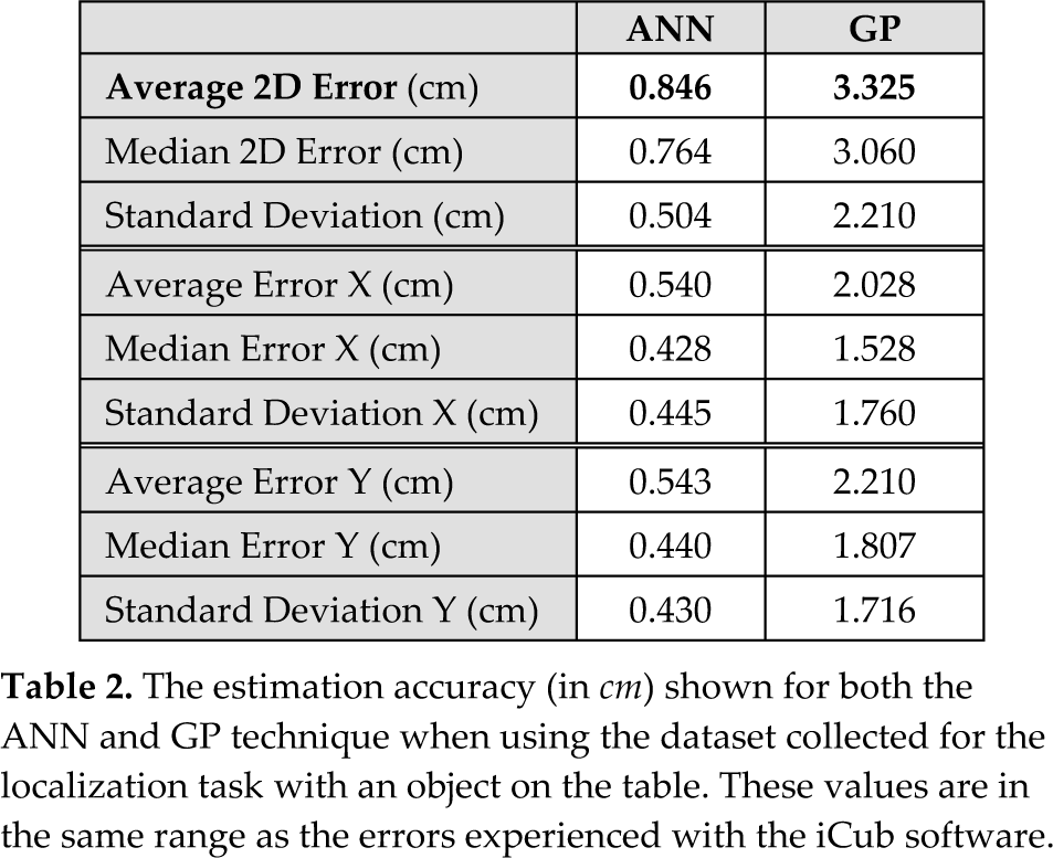
Table 2 compares the position prediction errors of the two techniques and shows that the neural network outperforms the GP method during learning. The errors reported are the best found during 10 learning runs. Figure 8 shows the actual and predicted locations for each test case. The top image shows the ANN approach, with tightly clustered estimations around the position, while the GP approach performs worse for most data points.
The estimation accuracy (in cm) shown for both the ANN and GP technique when using the dataset collected for the localization task with an object on the table. These values are in the same range as the errors experienced with the iCub software.

The difference between the estimated object positions (blue dots) and the actual object positions (red blocks). The top plot depicts the ANN results, while the bottom shows the GP.
Both approaches performed similarly well on both the training and test set, suggesting that the learned methods are estimating correctly and are able to generalize to the data collected (6×6 grid).
The GP method, while converging faster than the neural network, performs with an average accuracy of 3.3 cm. Although this performance is worse than the ANN, it is still sufficiently accurate to allow for simple reaching and grasping tasks. An advantage of this approach is, however, that the output is in human-readable form, allowing for easy and quick analysis, and transfer onto the robot. The following equations were found for the data:


An interesting observation from inspecting these is that only one of the camera images is used (features v0 and v1). This reduces the runtime by requiring only one image to be processed with object detection algorithms to provide all necessary (vision) inputs.
During training, both the ANN and GP approaches provide sufficient accuracy for object manipulation. The trained ANNs and the GP formulae were then tested on the real iCub hardware providing position estimates of objects in real-time. A YARP module was implemented to provide the state vector to both the trained neural network and the GP evolved formulae to compare their predictions. The experiments were performed using a cup, detected in the camera images using a specifically trained icVision filter.
To validate the predication errors of these learned methods, locations (on the table) and robot poses that were not in the original data set were applied. It was found that the GP out-performed (average error of 2.7 cm) the ANN (average error of 3.2 cm) on localization at previously unseen poses and locations. Both techniques were slightly less accurate than the iCub's ‘stereo Vision’ module (1.8 cm accuracy). This suggests an over-fitting of the ANN method on the collected dataset and a need for more data to interpolate better between points.
As another validation step, the performance of the two methods in terms of relative error was compared. Here the target object was moved in small increments around a central point. The measured locations are 1 cm and 2 cm offset in the direction of both axes. The accuracy was very high for both implementations, with the ANN yielding slightly better results, as can be seen in Table 3.
The relative estimation errors (in cm) when predicting the position using of objects not in the training set. A fixed robot pose was used.

Figure 9 shows a plot with the estimation of these specific measurements for the relative error. To allow for a comprehensive comparison, the current state-of-the-art iCub localization module (‘stereo Vision’) is also plotted.

Comparing the location errors of GP and ANN on the iCub hardware. The black filled boxes show the hand-measured RPs, whereas the circles represent the learning approaches, ANN and GP, respectively (empty circles are ANN measurements and filled are GP). The iCub ‘stereo Vision’ module is shown in green.
5.2 Estimating Object Locations in 3D Cartesian Space
The first experiment showed that the machine learning techniques are able to estimate the position of objects detected on the table. In this second experiment, we want to overcome the limitation that the objects are placed on the table and at the same time automate the lengthy process of collecting the dataset by hand. For this experiment a new dataset, including also a varying height, was collected to learn from. A high precision robotic arm, in our case a five DOF Katana arm by Neuronics [29], is used to position a red object in front of the humanoid (see Figure 10). Using the robotic arm, providing a high precision placement of the object (in mm accuracy), and our machine learning technique we are able to transfer the spatial information onto the iCub.

The iCub and the Katana robot working in a shared workspace to transfer spatial understanding from the precise industrial robot arm to our humanoid robot.
To collect the dataset, both robots are moved to randomly selected poses allowing for a random sampling of the configuration space. Once the robots reach their poses, as for the first experiment, camera images and the encoder positions of the iCub are stored.
The output value, to complete the entry in the dataset, is the 3D position information provided by the kinematics of the Katana arm, which is provided in the Katana's reference frame, CSK. These are easily translated into CSWorld using only a single offset on one axis. The iCub and Katana then both continued to another random pose to collect the next data point. All together 1036 RPs were collected. The time needed to collect the dataset was reduced to minutes (using a conservative maximum velocity for both robots) from hours for the previous experiment.
Another problem arises as in this setup multiple robots are sharing the same workspace and are controlled independently. The challenge is to prevent collision between the two robots, which would likely lead to damage to either or both the robots. An existing software framework called MoBeE [30] (previously VirtualSkin[31]) is used to detect and prevent the robots from moving into colliding poses. This detection is performed in real-time on the hardware using an approximate kinematic model of the two robots and the shared workspace, including the table and other obstacles.
MoBeE provides, by computing forward kinematics, and maintaining a geometric representation of the 3D robot/world system, a safety system for our two interacting robots. If a pending collision is detected, the controllers are disconnected from the real hardware and a reflex controller takes over. Once the two robots are returned to a safe pose the suspended controllers are reactivated. Figure 11 shows the view of the world model with both robot models loaded and visualized.

The iCub and the Katana kinematic models loaded into MoBeE to avoid collisions between the two robots while moving independently in the shared workspace.
In this experiment only the ANN approach was investigated due to its better performance compared to the GP approach in the first experiment. Again separate ANNs (this time three), using 10 hidden neurons and a single output neuron, predict the location along each single axis. The learning rate and momentum are again 0.35 and 0.1, respectively. The trained neural networks allow estimation of the object position in full 3D space, with a high enough accuracy to allow for grasping experiments. The average error on the dataset is for the X-axis 15.9 mm, for the Y-axis 43.1 mm and for the Z-axis 37.3 mm. This is again in the error range of current localization methods provided for the iCub. For learning, the network was again split into a training (80%) and test set (20%) to validate and avoid over-fitting.
Figure 12 visualizes the prediction error for all samples and axes in the dataset. A few outliers can be seen, but generally the prediction is accurate. The localization was tested by reaching for the red block held by the Katana manipulator (Figure 2) and reaching for a cup on the table, as shown in Figure 13.

The prediction errors per axis, after training the ANNs using the full 3D localization dataset.

The iCub estimates the position of the cup placed on the table in front of the robot. Note: the cup is placed directly under the arm, but due to the parameters of the camera and the different perspective in the two images this is hard to see. 6
6. Conclusion
We tackle the problem of localizing objects in 3D space from vision on a humanoid robot. We propose a machine learning approach that does not require prior camera calibration or a precise kinematic model. The performance of this biologically inspired machine learning technique is investigated. An Artificial Neural Networks (ANN) and a Genetic Programming (GP) approach are compared using a dataset collected on the iCub humanoid robot.
Both techniques provide a learned model which implicitly contains the camera parameters, usually delivered by a time-consuming stereo camera calibration, and the robot model, otherwise provided by lengthy determination of the precise kinematics. The learnt, ‘light weight’ models can easily be incorporated into embedded systems and other robotic platforms.
We present a method requiring a pre-collected dataset. Two experiments were conducted to see how this data can be collected and how well it can be learned.
The first experiment, predicting locations of objects on the table, showed that both are methods sufficient for real-world reaching scenarios, with the ANNs out-performing the GP method.
In the second experiment, the humanoid shared a workspace with a Katana industrial robot arm. Due to the ability to allow for safe interaction, the iCub was able to learn estimating positions in full 3D Cartesian space from the Katana. The accuracy of the trained ANN localization is sufficient to allow the iCub to reach for objects, as shown in Figure 13.
Our iCub was able to learn to estimate the locations of objects, when placed in the robot's workspace at arbitrary positions, in 3D Cartesian coordinates. In addition, the approach is robustly localizing, even while the robot is moving its torso, head and eyes 6 with enough accuracy for object manipulation. The results of both experiments show that the iCub can learn simpler ways to perceive the location of objects than the human engineered methods.
Footnotes
7. Acknowledgments
The authors would like to thank: Leo Pape (IDSIA) & Ugo Pattacini (IIT) for the Cartesian controller and stereo camera calibration of the iCub; Davide Migliore & Alexandre Bernardino (IST) for helping with the vision review. This research is supported by the European Union project IM-CLeVeR, contract FP7-IST-IP-231722.
4
YARP is a middleware that allows easy, distributed access to the sensors and actuators of the iCub humanoid robot, as well as to other software modules.