
Abstract
In this paper, a rotating flexible link impacting a granular media is studied. The influences of initial impact velocity and impact angle are examined. The resistance forces are expressed as the sum of a dynamic frictional force (velocity-dependent) and a static resistance force (depth dependent). The penetrating angle increases with initial impact velocity as expected. However, the stopping time decreases with initial impact velocity for all initial impact angles for the considered system.
1. Introduction
The impact with a granular media is a very interesting phenomenon because of the characteristics of granular materials which are similar to a solid with a flow which is similar to a fluid. The focus of recent works has been observations of low speed impact and the correlation between initial velocity and stopping time in the granular media [1].
In [2], the penetration of large projectiles into dry granular media is studied. The authors proposed the resistance force model as a velocity-dependent drag force and depth-dependent friction force. The depth-dependent friction force models have been developed for horizontal motion in [3–6] and for vertical motion in [7, 8]. Researchers analysed the impact results including the impact cratering, the impact depth, and the stopping time based on their model of resistance force. In [9], the stopping time is a function of the geometry and the initial velocities.
The time dependence of the velocity of the projectiles is studied in [10]. The authors found that this dependence is not a linear function of the time and the granular media have a similar behaviour to a fluid during initial impact.
[1] has sparked new interest in the field of vertical impact with a granular matter. The resistance force model proposed by [2] is applied and verified for the motion of a rigid sphere with the help of a line-scan digital CCD camera. They analysed how rapidly a sphere impacting a granular media slows upon collision.
Li et al. examine the performance of a legged robot on granular media [11]. The properties of the medium, the limb frequency and the gait are analysed. The authors give a detailed discussion of a rotary walking locomotion model. The vertical component of the granular media force acting on the leg is a function of depth and leg-shaft angle.
The performance of a small legged robot on a granular media is systematically studied in [12]. A new anisotropic granular penetration force that can predict the speed is introduced. A predictive model for legged robots is developed.
The granular materials are ubiquitous and the impact with a granular medium can take place in various areas such as robotics, human and animal locomotion, tracked vehicles, heavy duty construction equipments and extraterrestrial explorations. Multi-legged robots cannot avoid continuous impact with the granular materials.
This study will provide developments that would be applicable in the design of impacting systems such as: walking machines, variable geometry wheeled and tracked vehicles, active cord mechanisms, and legged robots.
In this study we focus on modelling, simulation and experiments of the kinematic links impacting a granular medium using the resistance force model as the sum of a velocity-dependent drag force and a depth-dependent resistance force. We also analysed the relation among initial impact velocities, stopping time and penetrating depth based on the experimental and simulation results. To the best of our knowledge this is the first time a mathematical model has been proposed, analysed and experimentally verified for the impact of kinematic links impacting into a granular matter.
2. Force analysis
The resistance force of the granular medium on the body from the moment of impact until the body stops is very important. There are different models for the granular resistance forces that act upon a body during the penetration process. For viscous drag Bingham's model F R = F0 + bv, where v is the velocity of the body relative to a medium and b is a coefficient, has been utilized. This model was originated for viscoplastic materials that behave as a solid at low stress and as a viscous fluid at high stress. Using this model, [13] calculated the penetration of spheres into a loose granular material and Bingham's equation has recently been advocated for granular impact. Poncelet's model F R = F0 + cv2, where c is a drag coefficient, originated from high speed impact and has been used for ballistics applications [9]. [14, 15] suggested a force model including Bingham's and Poncelet's models, as F R = Av2 + Bv + C for the study of projectile penetrating sand, where A is a classical fluid dynamic drag parameter, B is a parameter due to kinetic fiction, and C is a deceleration force. Recent research studies [3–8] indicate the static resistance force, defined as a constant for Bingham's and Poncelet's models, depends linearly or nonlinearly on the depth of penetration. In [16], the resistance force made up only by static force F R = kz is considered where z is the penetrated depth and k is a constant.
[2] proposed a resistance force based on Poncelet's model and on the static force considered in [6]. The total resistance forces acting on a moving body into a granular matter can be generalized as the sum of the static force characterized by a depth-dependent friction force as well as the dynamic frictional force characterized by a velocity-dependent drag force
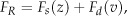
where F s is the static resistance force and F d is the dynamic frictional force. With this approach the resistance force model incorporates the solid-like and fluid-like characteristics simultaneously.
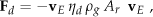
2.1. Dynamic frictional force Fd
The dynamic frictional force F d is conceptually the same force as the “drag” used in fluid dynamics. When the external driving forces (including tilting and shaking) exceed the stationary condition the individual grains lose the stationary state in their contacts and the granular material begins to fluidize. From this fluid-like behaviour of the granular matter the resistance force is assumed to be a drag force impeding the body motion [17–21]. Once the body penetrates the granular matter after impact, the matter contacting with the moving body partly acts like a fluid and the resistance force begins to be generated. The dynamic frictional force is a velocity-dependent force, starts when the link touches the granular matter and ends when the link is at rest. The dynamic frictional force F d has been modelled as a linear drag force or a quadratic drag force. Bingham's model (linear drag) has been used for low speed granular impact and Poncelet's model (quadratic drag) has been used for high speed applications [9].
The research results using a dilute granular flow condition which is not affected by the static resistance force [17, 19, 21] and the studies at low speed impact [1, 2] show that the quadratic drag force model is better for the dynamic frictional force F d than the linear equation model even at a relatively low speed. The dynamic frictional force can be modelled as
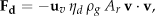
where
2.2. Static resistance force Fs
This static resistance force does not depend on the velocity or the acceleration of a body and acts as an internal stress. Therefore this force acts as a main resistance force when a body penetrates a granular medium at low speed. The presence of this force not existing in a fluid can be observed easily. When a body is put on a granular material, the body starts to penetrate vertically through the granular material and does not sink beyond a certain depth. The body stops penetrating the material due to this static resistance force. In an ordinary fluid the body will sink without limit.
In spite of the fact that this resistance force plays an important role for a body penetrating a granular material, the force had not been highlighted in earlier studies. Most models, including the Bingham and Poncelet models, have considered this force as a mere constant. The theoretical modelling of this force originated from the characteristics of a granular material even in a stationary state but it is not that easily determined. Various research results explain the origin of this resistance force as a network of forces generated from contacts between granules [22–27]. For a penetrating body there are interactions between the granules in the vicinity of the body and the other granules located in the container, and in this way a force chain will be created. The force is transmitted following granular medium movement as a chain reaction beginning with displacements of granules placed in the path of the moving body and ending with large scale reorganization of granules in the container. The forces and their spatial correlations do not represent a fixed structure and the force chains are connected or disconnected continuously until the rest of penetration takes place. This process is strongly influenced by the properties of a granular matter, the external shape of a body, the packaging state of the medium, and even the form of the medium container [5, 28]. Any changes during the penetration can increase the uncertainties of the propagation chain. These uncertainties in a real impact problem make the forces not propagate uniformly through the granular matter and localize along certain directions. This irregular propagation force and the chaotic particle reorganization cause fluctuations of the static resistance force in direction and magnitude [3, 5, 29–31]. Due to this complicated process of transmitting the force, there are few studies that completely describe the static resistance force [7]. In our research we will consider the horizontal and vertical static resistance forces developed by theoretical and empirical approaches.
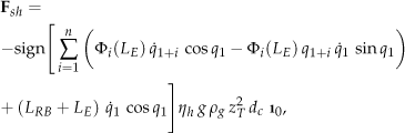
2.3. Horizontal static resistance force Fsh
The horizontal static force is defined as an internal resistance force acting on the horizontal direction. When a body penetrates a granular material, it is not easy to separate and measure this force individually without the effect of dynamic force F d . The experiments on horizontal static resistance forces have been performed at very slow speeds such as 0.04 – 1.4 mm/s [4–6].
[6] applied a probability approach to model this resistance force. They used the force chain model developed by [22] in order to find the mean horizontal static resistance force. According to the chain model of [22], the force chains transmitting the propagation of contact forces are built up based on the force fractions that act on a given particle of the matter. The force fraction is unequally split and transmitted to the adjacent particles. The calculated minimum force F for a vertically immersed cylinder type body is F = η h g ρ g H2 d c , where g is the gravitational acceleration, H is the immersed length of the cylinder, d c is the diameter of the cylinder, and η h is an experimental constant [6]. The horizontal static resistance force of the cylinder including the state of immersion, at any slope, can be generalized as
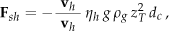
where
2.4. Vertical static resistance force Fsv
The vertical static force is defined as an internal resistance acting on the vertical axis. Simple models consider this force as a constant [9, 13] or as a linear function of the immersed depth of the body [1, 16]. The vertical static force is also modelled as a nonlinear function of the immersion depth [7, 8]. Experiments show the granules contacts increase exponentially with the external force [24, 25]. The effects of the container bottom boundary increase the nonlinearity of this resistance force [8, 28].
[7] suggested an empirical equation with coefficients calculated from the experimental data as
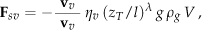
where
Experimental data show that the inclination of the body has little effect on the vertical static resistance force, but the moving directions drastically change this force [7]. For a cylinder type body, whether the axis is vertical or horizontal, η v = 10, λ = 1.4 for plunging motion and η v = 0.5, λ = 1.7 for withdrawing motion.
3. Dynamics of a rotating link
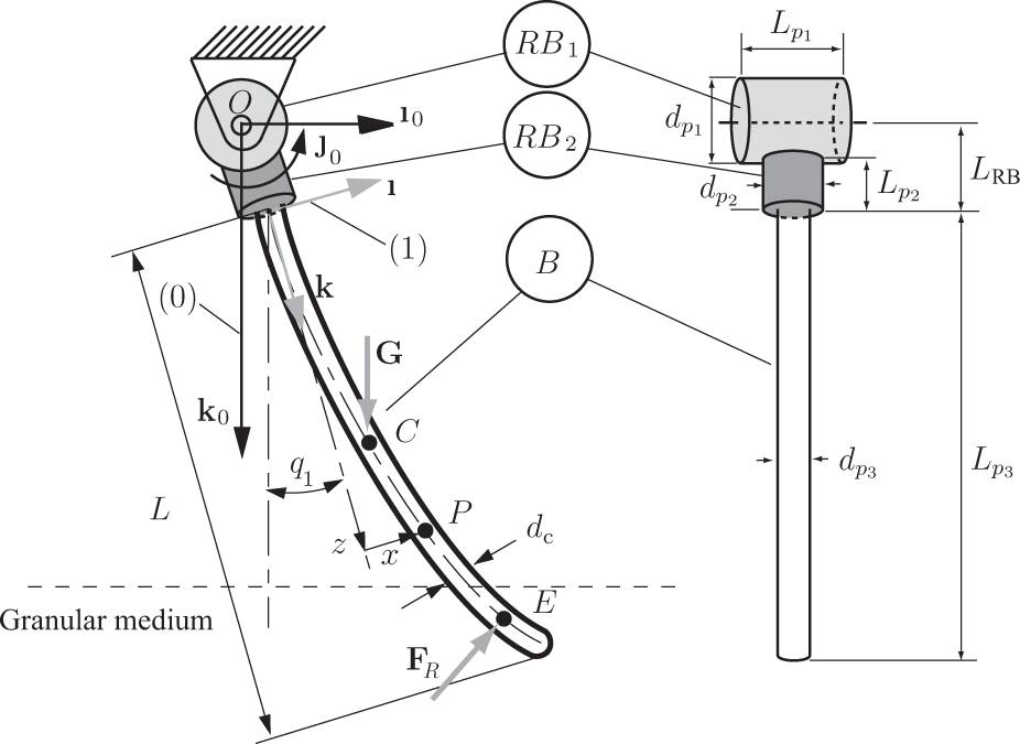
In the case of a cantilevered elastic link composed of one end supported by a rigid body as shown in Figure 1, the boundary conditions for the flexible link are cantilevered at one end and free at the other end.
Cantilevered elastic link
As shown in Figure 1, the cantilevered elastic link applied to the modelling is supported by rigid bodies RB1 and RB2. The rigid body RB1 has the diameter dp1 and the length Lp1 . The rigid body RB2 has the diameter dp2 and the length Lp2. The flexible part of the bar, B, has an uniform flexible link of the length Lp3 = L
B
= L, the diameter dp3 = d
c
, the cross sectional area Ac=πd
c
2/4, the flexural rigidity EI, and density ρc. The length from the origin to the rigid body end is L
RB
= dp1 /2 + Lp2 and the density of the rigid bodies is the same as that of the elastic link. To characterize the instantaneous configuration of the elastic link, the generalized coordinates q1 and qi+1 are employed. The generalized coordinate q1 denotes the radian measure of the rotation angle between the undeformed link and the horizontal axis. The generalized coordinate qi+1 denotes the deformation of the elastic link part of the pendulum. A fixed reference frame (0) of unit vectors [
3.1. Kinematics
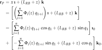
The deformations of the cantilevered elastic rotating link can also be discussed in terms of the elastic displacement x(z, t) of a generic point P on the elastic part B of the pendulum. The point P is situated at a distance z from the point at the first end of the elastic link B. The displacement x can be expressed as

where Φ i (z) is a shape function of the elastic link by z, the elastic generalized coordinate q1+i (t) is a function of time t, and i is any positive integer.
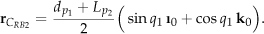
The position of the mass centre of the rigid body RB1 is the origin point O and the position vector from the origin O to the mass centre of the rigid body RB2, CRB2, is represented as
The position vector from the origin point O to a generic point P of the link B, in the mobile reference frame of unit vectors [
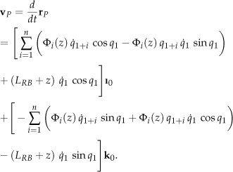
The velocity vector of the generic point P of the elastic link B is calculated in the fixed reference frame (0) and has the value
The acceleration vector of the point P in the fixed reference frame (0), of unit vectors [
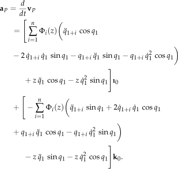
The angular acceleration of the link in the reference frame (0) in terms of the fixed unit vector

3.2. Equations of motion
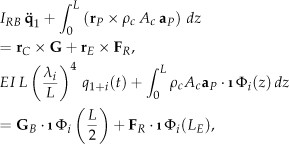
Newton-Euler equations can be used to find the differential equation of motion. A moment equation before impact can be written as
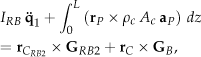
where I
RB
is the mass moment of inertia of the rigid body and the gravity forces
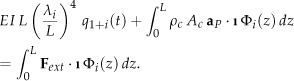
Because the external forces acting on the elastic link of the pendulum are the gravity force G
B
and the joint reaction force
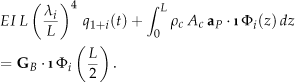
Differential equations (9) and (11) represent the equations of motion for the cantilevered elastic link before impact.
While impacting a granular medium, an additionally added external force is restricted to the resistance force F R . The equations of motion for the cantilevered elastic link during impacting are given as
where
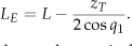
The immersed depth z
T
, the vertical component of the position vector of the end point τ, is calculated by as Z
T
=
where the velocity vector

The horizontal and vertical static resistance forces,
where the immersed volume V is calculated as
The resistance force
3.3. Simulation results
The symbolic Mathematica was used to find the ordinary differential nonlinear equations of motion. To solve numerically the equations of motion a Runge-Kutta Mathematica function was utilized. For the ODE problem the instants of the specific events are important to detect the time at which the normal and tangential velocity are zero. The Mathematica EventLocator function was used to handle the moments when the velocity is changing the sign.
The flexural rigidity of the link is EI = 15.1642 N m2. The simulations are performed for different impact angles and different initial impact angular velocities (q̇1(0) = −1.75, −3.38, and −4.66 rad/s for q(0) = 22°, q̇1 (0) = −3.31, −6.24, and −8.41 rad/s for q(0) = 31°, q̇1 (0) = −2.66, −6.47, and −9.06 rad/s for q(0) = 45o, and q̇1 (0) = −2.70, −6.54, and −9.17 rad/s for q(0) is 61.5o). Table 1 shows the stopping time results for the elastic model, t s . The stopping time is measured from the impact moment until the angular velocity of the link q̇1 becomes zero. Only the first mode of the shape function is considered. As shown in Table 1, the pendulum stops more quickly when the system impacts the granular medium with high velocity. The results show that the faster the impact velocity, the sooner the link stops. The initial impact angle, q1 (0), is the angle when the link hits the ground first.
The displacement showing the maximum elastic deformation of the link becomes larger when the initial impact velocity and the initial impact angle increase as shown in Figure 2. The values of the elastic deformations are very small. The body flexibility is not an issue and both simulations (rigid and flexible) should not differ significantly for this specific impact. The elastic deformation is an issue for the hard surface impact (and definitely more mode shapes are needed). For the impact on sand, the body flexibility is negligible for this specific application.
Maximum elastic displacement for the initial impact angle q1 (0) = 22°, 31, 45°, 61.5°
Simulation stopping time for the cantilevered elastic link
3.4. Experimental set up
Figure 3 shows the compound pendulum with the following dimensions: the length Lp1 = 0.019812 m, Lp2 = 0.01524 m, L p3 = 0.23876 m, the diameter dp1 = 0.01905 m, dp2 = 0.01524 m, and dp3 = 0.00635 m. The density of the link is 7.7 × 10³ kg/m3. The infra red (I.R.) markers are located on the rotational joint point and the centre of the Lp3.
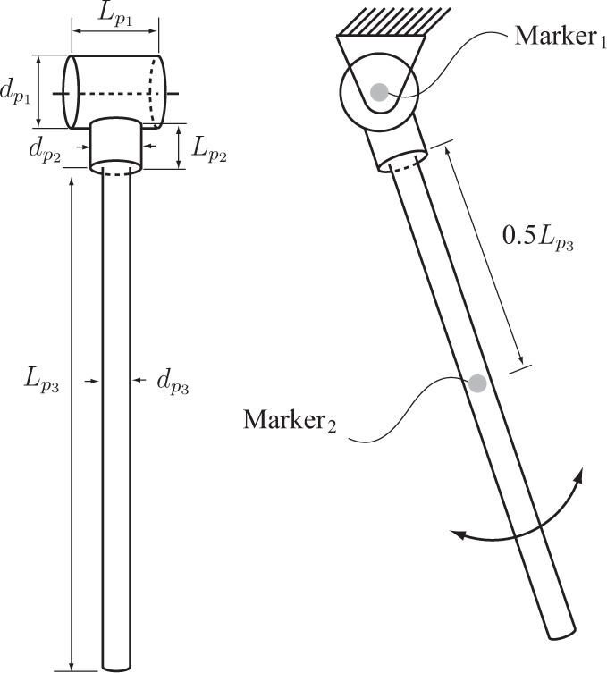
Geometry of the rotating link for experiments
In this study, as the motion capturing system to measure and digitize the position of the impact objects, a Northern Digital Inc. (NDI) optotrak 3020 system is used. This system is composed of a position sensor, a control unit, a stroboscope, I.R. markers, and a PC as shown in Figure 4. The system can measure the position of the markers within the RMS accuracy of 0.1 mm and can track up to 256 markers simultaneously with a sample up to 3500 markers/s. The system does not require a calibration process. The motions of the rigid link are recorded using the two I.R. markers. The position sensor captures the position of the I.R. markers attached to the bodies at constant sample rates and measures 3D position data. The elastic deformation of the link is negligible. The PC is used for the operating software controlling the hardware system, and saving and transforming the measured data. In the experiments, the positions were measured using a 3D data Cartesian coordinate system at 500 frames/s.
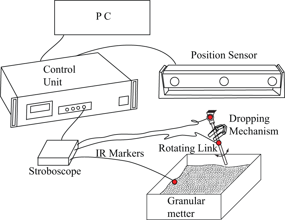
Motion measurement system
Many kinds of granular materials exist. These include grains such as rice, soils including sand, and artificial granules such as fertilizer, glass beads and ball bearings. The applied density of a granular medium for the simulations, ρ g , is 2.5 × 10³ kg/m3. The numerical value of the density is originated from the physical property of the granular medium, “Play sand” (Quikrete 1113-51) utilized in the impact experiments. The resistance force coefficients are: the dynamic frictional force coefficient η d = 6.5, the horizontal static resistance force coefficient η h = 8, and the vertical static resistance force coefficients η v = 22 and λ = 1.1. These coefficients were determined from experimental data. The gravitational acceleration g is applied as 9.81 m/s2. The field of low speed impact with a granular medium is related to developing multi-body kinematic chain systems such as multi-legged robots for surveillance or carrying, and these systems cannot avoid slow impact with diversified outfield granular materials including soil and sand. From this view point, sand is considered more appropriate and beneficial than glass beads or other artificial granular medium. The dimensions of the impact test box are 0.45 m×0.32 m×0.09 m (W×L×H) and the height of the sand in the test bed is 0.075 m.
Figures 5, 6, 7, and 8 represent the penetrating angle q1 and the angular velocity q̇1 of the experimental and the simulation results for the impact of the link. The experiments and the simulations are performed for different impact angles and different initial impact angular velocities (q̇1(0) = −1.75, −3.38, and −4.66 rad/s for q1 (0) = 22°, q̇1(0) = −3.31, −6.24, and −8.41 rad/s for q1 (0) = 31°, q̇1(0) = −2.66, −6.47, and −9.06 rad/s for q1(0) ≈ 45°, and q̇1(0) = −2.70, −6.54, and −9.17 rad/s for q1(0) is 61.5°) from the impact moment until the angular velocity of the pendulum, q̇, becomes zero. The thick lines show the results of experiments and the black lines represent the simulation results. The resistance force coefficients are the same for all the simulations of the impact of the link.
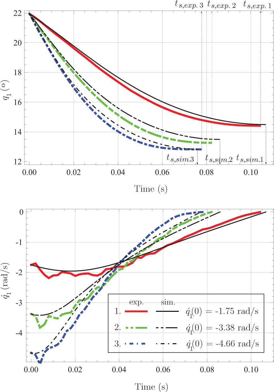
Experimental and simulation results for q(0) = 22°
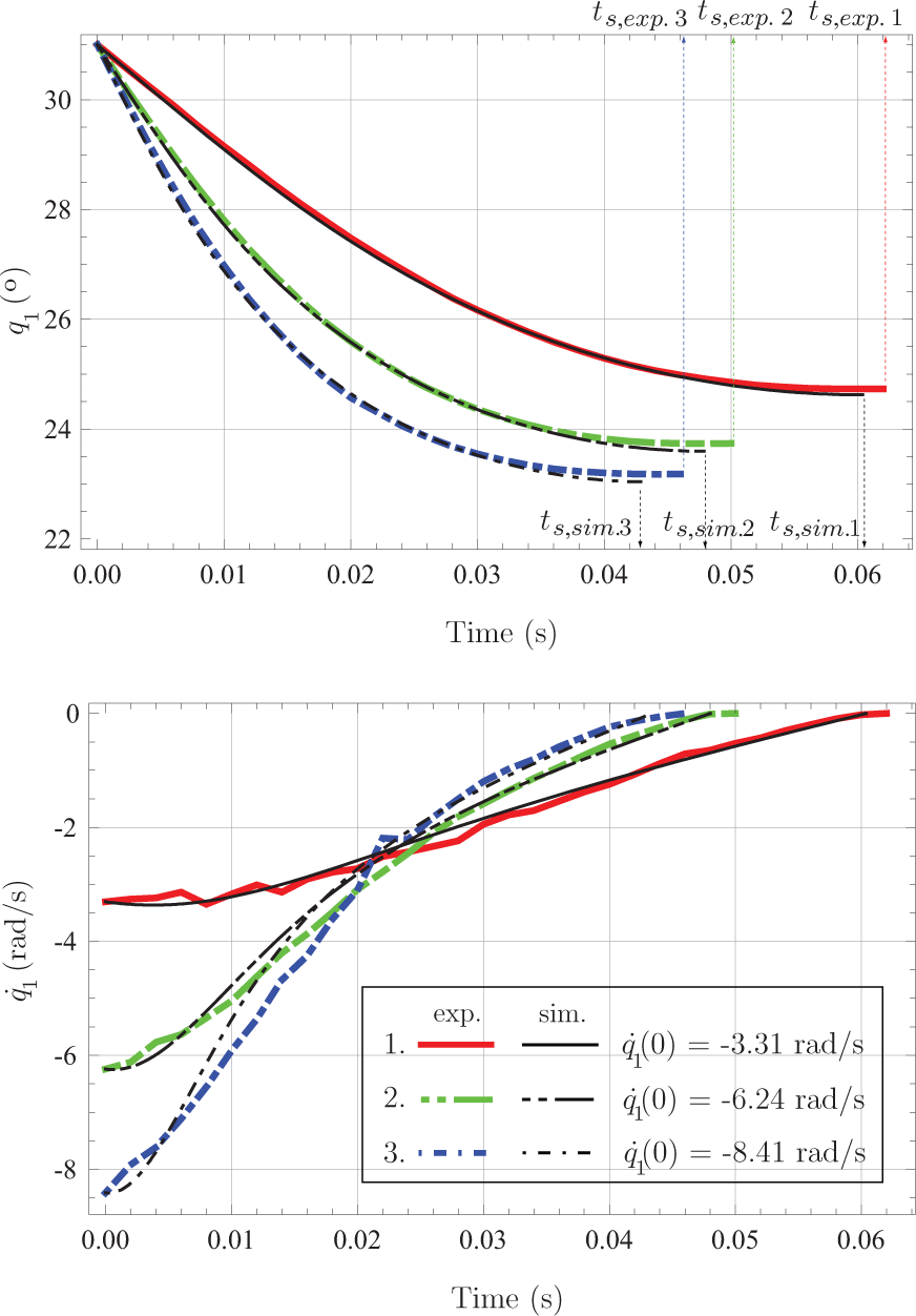
Experimental and simulation results for q(0) = 31°
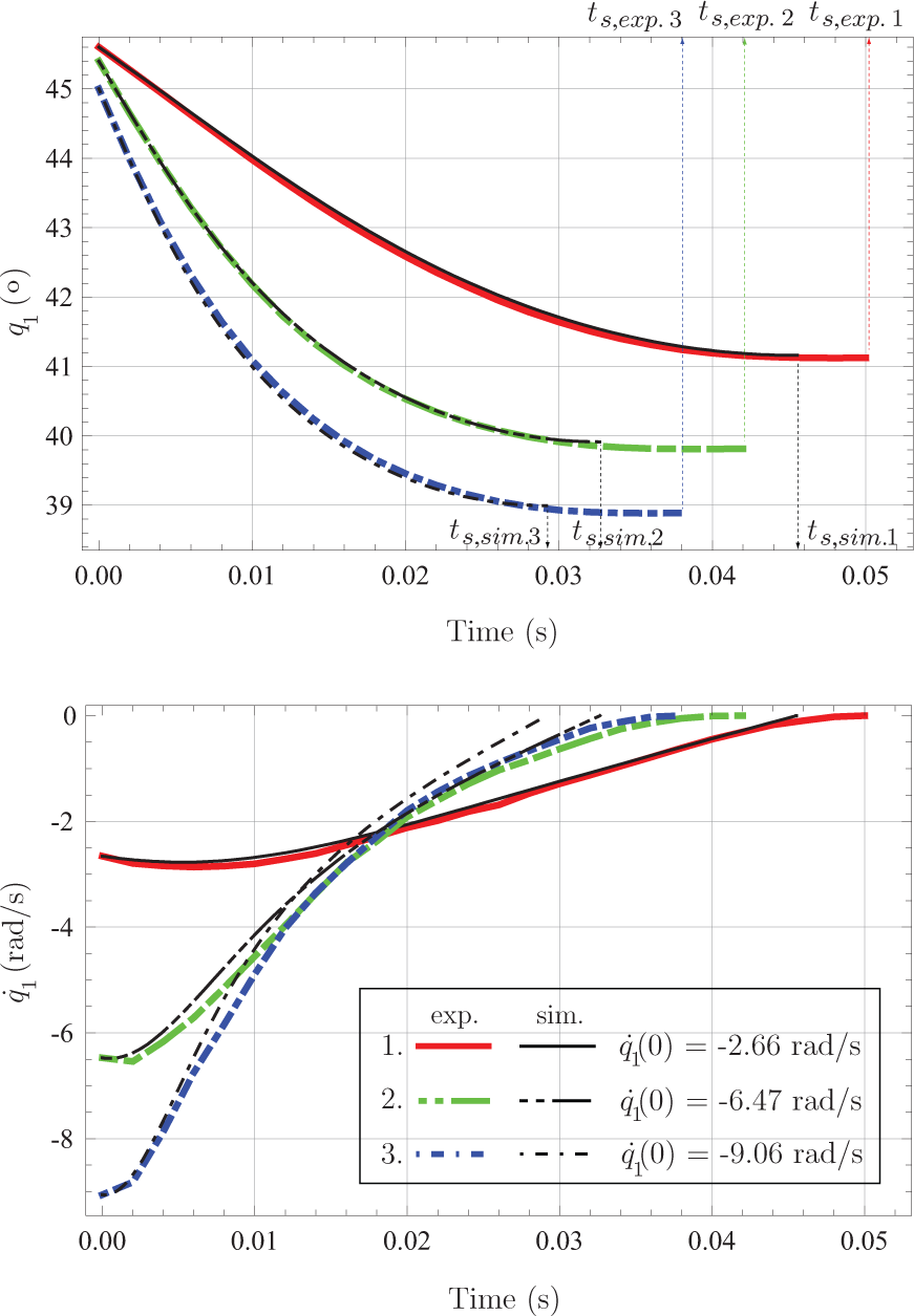
Experimental and simulation results for q(0) = 45°
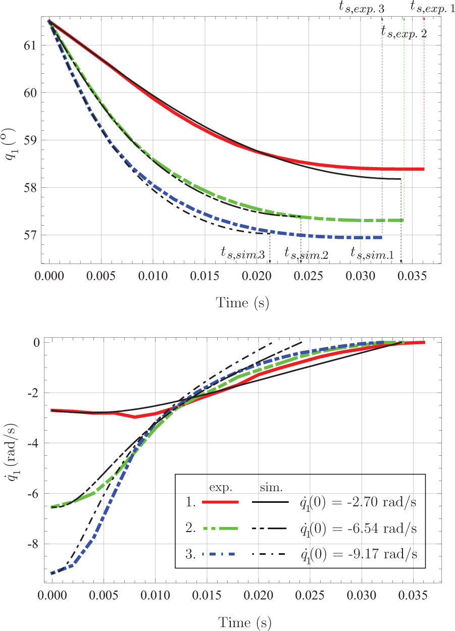
Experimental and simulation results for q(0) = 61.5°
4. Experimental results
The penetrating angle of the link increases with the initial angular velocity for all the cases as shown in Figures 5, 6, 7, and 8. The experimental results also show that the stopping time of the link decreases when the initial impact velocity increases. In these experiments and simulations, the stopping time is defined as the time period starting from the moment of impact and ending when the velocity of the object into the granular matter is zero. The experimental and the simulation results of the compound pendulum show the decrease of the stopping time for different oblique impacts with a granular medium. The phenomenon that the impact of a rigid body stops more rapidly as the initial impact velocity increases (having been confirmed by the experiments and the simulation results) is observed for the impact of the rotating link.
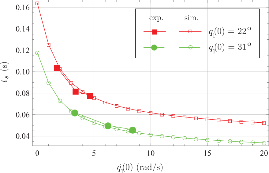
Figure 9 shows the stopping time of the rotating link for two impact angles. The large markers represent the experimental results and the small markers depict the simulation results. The stopping time decreases when the initial impact angular velocity increases. However, the decrease of the stopping time diminishes for higher values of the angular velocity.
Stopping time results
5. Conclusions
In this study the dynamics of an impact with a granular medium is studied. Even though granular mediums are ubiquitous and the phenomenon of impact with them takes place frequently whether artificially or naturally in industry and nature, studies related to low speed impact with a granular medium have not been sufficient for understanding the dynamics of the impact. At present, most studies are restricted to the impact in the vertical direction and have been limited to experiments using a spherical shape. In this study the resistance force generated by the granular medium is a velocity-dependent, dynamic frictional force, and a depth-dependent, static resistance force.
For the impact on sand, the body flexibility is negligible for this specific application. The simulation results show that the stopping time decreases when the initial velocity of the impact object increases. It is confirmed that for an oblique impact with a granular medium the stopping time decreases when the initial impact velocity increases. Even though the stopping time decreases, the penetrating distance of the body increases as the initial impact velocity increases for all cases.
The simulation and experimental results performed for initial impact angles (22, 31, 45, 61.5°) and for initial impact angular velocities (−1.75 ˜ −9.17 rad/s) show how fast the impact velocity of the rotating link is - the sooner it stops, the deeper it penetrates. There is a good agreement between the simulation results and the experimental results.
Future studies will analyse the impact of complicated geometrical links and kinematics chains with multiple contacts. This will require an understanding of the physics related to the granular penetration. A realistic expression of the contact force can generate better control strategies and robot link designs.